Note : Les descriptions sont présentées dans la langue officielle dans laquelle elles ont été soumises.
CA 02679877 2009-09-02
WO 2008/114063 PCT/GB2008/050207
Capillary
This invention relates to a capillary, and in particular to a capillary
channel adapted
for improved flow.
The use of small channels in which liquid flow is controlled by capillary flow
forces
is becoming more common in in vitro diagnostic devices (IVD). Channels of only
a
few tens to a few hundreds of micrometres in size mean sample and reagent
volumes
can be minimised, often to a few microlitres ( L) thereby reducing cost,
instrument
complexity and test times. As a result, manufacturability is simplified which
offers
increased margins and excellent repeatability, both of which are important
since the
marketplace primarily demands single-use devices. Such devices are ideally
suited to
use by non-specialist operators in near-patient and "point-of-care" (PoC)
applications
especially where the chemistry involves the use of antigen/antibody reactions
in an
immunoassay forrnat.
In a typical device 2 as shown in Fig. 1, a fluid sample, such as a satnple of
biological
fluid, e.g. blood, is introduced into the device 2 at a sample inlet 4. The
fluid sample
is drawn into a first reagent microchannel 6 by capillary forces and
subsequently
caused to move in order to mix with liquid and/or solid reagents, for example
in a
mixing labyrinth 8, before finally being moved via a second reagent
microchannel 10
to a sensor area 12 of the device 2. Movement can be achieved, for example, by
air
flow (pressure or vacuum), by hydraulic movement using a "finger pump", or by
electrical or electrostatic means. The mixing labyrinth 8 is not essential but
is
included to speed up mixing which can be achieved, albeit less efficiently, by
passing
the materials to be mixed through a simple restricted orifice.
Previously, the most common method of fabrication of such disposable devices
was
by injection moulding. Increasingly, the preferred manufacturing method is
lamination of suitably shaped or die-cut sheeted materials with pressure
sensitive
adhesives (PSAs) to form linear channels a few millimetres in width and tens
to
hundreds of micrometres deep. One problem with such channels where the aspect
ratio (the ratio of the width to the depth) is in the range 10 to 100 is that
movement of
fluid back-and-forth, for example to encourage mixing of a dried-down reagent,
and
CA 02679877 2009-09-02
WO 2008/114063 PCT/GB2008/050207
the multiple drying and re-wetting of the surface that ensues, tends to form
bubbles or
air-filled voids that may deleteriously interfere with the signal generated
when the
sample/reagent mixture is moved to the sensor area.
This bubble formation is frequently the result of differences in
hydrophobicity and
hydrophilicity of the surfaces forming the channels. Fig. 2 shows a capillary
channel
14 having a first portion 16 and a second portion 18, in which the second
portion 18 is
wider than the first portion 16. Bubble formation may occur as the fluid
sample 20
enters the capillary channel. At point (a) the fluid enters a wider portion of
the
capillary channel and at point (b) the fluid forms a meniscus. As the fluid
moves
along the capillary channel, contact between the fluid and the wall of the
capillary
channel increases on account of the shape of the channel and variations in the
surface
energy leading to unwanted bubble 22 formation at point (c).
Thus, in a rectangular capillary, under circumstances where the edges of the
channel
are linear the capillary force at the edges appears significantly greater than
in the
centre of the channel. This encourages the liquid to "chase" up the edges far
ahead of
the bulk of the liquid, causing the formation of bubbles in the centre of the
channel.
This bubble formation can, to some extent, be mitigated by coating the
surfaces
involved with suitable chemicals to counteract the enhanced capillary action
that
occurs at the edges of a rectangular capillary, evening-out the "wetability"
of the
surfaces involved and the liquid flow. This, however, introduces another step
or steps
into the manufacture of the device, increasing cost and complexity, and the
materials
involved in changing the properties of the surfaces can interfere with the
composition
of the fluids and subsequent analyte detection dynamics, especially when they
re-
dissolve in the fluid passing over them.
Alternatively, some IVD developers have attempted to improve the wetability of
the
surface by changing the surface morphology to encourage capillary action at
the
micro level, for example by adding micrometre-sized pillars, peaks or steps.
See US
2005/0136552 for an example of this methodology. The add'it'ion of such
roughened
surfaces is readily achievable by, for example, micromachining of mould tools
where
the components are injection moulded.
2
CA 02679877 2009-09-02
WO 2008/114063 PCT/GB2008/050207
However, introducing a roughened surface is much harder to achieve if the
disposable
device is fabricated from die-cut sheeted material, without employing a
complex
multi-step thermoformed or embossed pre-treatment. Such complex multi-step
methods are prohibitive in terms of cost in disposable laminated devices.
There
remains a requirement in the art, therefore, for a solution to the problem of
bubble
formation in a capillary channel formed as a laminated structure.
Accordingly, the present invention provides a capillary channel comprising a
first pair
of opposing walls defining a width and a second pair of opposing walls
defining a
depth, wherein the channel has an aspect ratio of 10-100 defined as the ratio
of the
width to the depth of the channel and wherein an internai surface of at least
one of the
second pair of opposing walls is roughened.
The present invention will now be described with reference to the accompanying
drawings, in which:
Fig. 1 shows a sensor incorporating capillary channels according to the prior
art;
Fig. 2 shows a conventional capillary channel;
Fig. 3 shows a capillary channel in which the width is greater than the depth
according to the present invention;
Fig. 4 shows a capillary channel of the present invention;
Figs 5-7 show discontinuities in the wall of capillary channels according to
the present
invention; and
Fig. 8 shows a sensor incorporating a capillary channel of the present
invention.
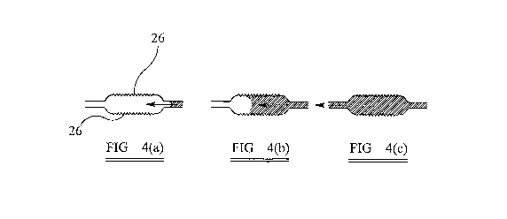
Fig. 3 shows a capillary channel 14 according to the present invention. The
capillary
channel 14 comprises a first pair of opposing walls 24 defining a width and a
second
pair of opposing walls 26 defining a depth, wherein the width is greater than
the
depth. Fig. 4 shows the capillary channel 14 of the present invention in cross
section
in which the internal surfaces of both of the second pair of opposing walls 26
is
roughened. Either one or both of the second pair of opposing walls 26 may be
roughened although, preferably, both are roughened. As the fluid sample is
caused to
move from point (a) via point (b) to point (c), the roughened surface
minimises or
prevents bubble formation.
3
CA 02679877 2009-09-02
WO 2008/114063 PCT/GB2008/050207
In a typical device formed as a laminated structure, the channels 14 are cut
into a
spacer, for example die-cut into a plastics film layer. The spacer is
typically has a
thickness of 50-500 m. Suitable materials include polyester (e.g. Mylar,
Melinex) or
polycarbonate (e.g. Lexan). The spacer is then laminated between two planar
substrates ("lids") formed of a similar material to the spacer using PSA to
form the
required flow path. Thus, in a preferred embodiment of the present invention,
the
capillary channel comprises a laminate structure wherein the first pair of
opposing
walls is formed from two planar substrates and the second pair of opposing
walls is
formed from channels cut into a spacer sandwiched between the two planar
substrates.
The capillary channel of the present invention preferably has a width of 1-5
mm; the
channel also preferably has a depth of 10-500 p,m. The channel has a width
which is
greater than the depth and the channel has an aspect ratio of 10-100 defined
as the
ratio of the width to the depth of the channel.
It has been found that the flow in a capillary channel can be evened-out by
roughening
the surface of the second pair of opposing walls 26. Roughening may be
achieved
using techniques known in the art, for example adding small ridges, steps or
"teeth" to
the second pair of opposing walls 26, i.e. the die-cut edges of the PSA
laminated
spacers.
Surprisingly, the roughened surface retains small quantities of fluid and/or
air when
the bulk sample is moved through the channel which appears to encourage flow
in the
centre of the channel, minimising large bubble formation, when the bulk liquid
is
returned to the channel. It is surprising that the roughening of the narrower
or
shallower surfaces has the desired effect.
An advantage of the present invention is that the first pair of opposing walls
does not
need to be roughened and preferably, the internal surfaces of these walls are
smooth.
However, an internal surface of one or both of the first pair of opposing
walls may
also be roughened if desired.
4
CA 02679877 2009-09-02
WO 2008/114063 PCT/GB2008/050207
Roughening of the surface introduces one or more discontinuities into an
otherwise
smooth surface. The roughened surface may comprise square, rectangular,
circular
and/or triangular discontinuities. The discontinuities may be raised or
depressed. The
discontinuities tend to have a height (or depth) of about 1-2,000 p.m.
Preferably, the
discontinuities repeat every 10-2,000 p,m. Possible shapes of the roughened
surface
are shown in Figs 5, 6 and 7. Fig. 5 shows a syrnrnetricai repeating pattern
of square
or rectangular shapes which preferably repeats every 10-2,000 m. Fig. 6 shows
an
asymmetrical repeating pattern of square or rectangular shapes which
preferably
includes at least one square or rectangle every 10-2,000 ~tm. Fig. 7 shows a
symmetrical repeating pattern of triangular shapes which may be upright
triangles or
"saw-tooth" in shape and which preferably repeats every 10-2,000 q.m. The
angular
portions of the discontinuities, such as the tops of the saw-teeth or the
inner angles at
the base of the square-shaped discontinuities or notches, may be radiused
(i.e. having
small inner and outer curves rather than being "pointed" angles, like the
corners of a
triangle or square). Radiusing these corners will further improve the flow
characteristics of the channels. Preferably the radiused angular portions have
a radius
of 0.1-1 mm.
Although a plurality of discontinuities is preferred, a single discontinuity
(notch) is
sufficient if it is placed near the bottleneck at the exit of chamber 14. More
preferably,
two discontinuities are placed opposite one another.
Without wishing to be bound by thcory, the present invention is believed to
work in
four possible ways, some or all of which will contribute to the reliability of
flow in
any particular case:
Firstly, the roughened surface means that the fluid at the edges of the
capillary
channel has to travel farther, i.e. in and out of each discontinuity, rather
than running
straight up the edge, and this increased distance slows the fluid at the edge
without
slowing the fluid in the centre.
Secondly, the roughened surface reduces, but does not eliminate, the sample
chasing
up the spacer edges by interfering with the enhanced capillary action that is
normally
seen at the capillary walls. Thus bubble formation is discouraged in the
mixing
5
CA 02679877 2009-09-02
WO 2008/114063 PCT/GB2008/050207
chamber. In practice, the roughened surfaces do not have to become filled in
order to
see their beneficial effect. Indeed, small quantities of air trapped in these
notches
breaks up the enhanced capillary action normally seen at the wall. Where fluid
does
chase up the edges during filling of the mixing chamber, when fluid movement
ceases
the centre portion of the fluid "slug" continues to move forward to meet the
level of
fluid at the edges. This effect is strong enough that sometimes the central
fluid portion
ends up in advance of the liquid at the edges providing a "convex meniscus"
effect.
This is likely to be the result of surface tension on the front edge of the
fluid sample.
Thirdly, when the fluid flow is "back-and-forth", it encourages the retention
of small
amounts of fluid between the discontinuities of the spacer evening-out the
"wetability" of the edges of the channel.
Fourthly, when air bubbles do form they tend to become trapped at the (air
filled)
discontinuities and remain static during fluid movement. Thus they are
discouraged
from being transferred into the reading chamber with the liquid sample. They
are
presumably being driven to combine with air in the notches in order to
minimise the
surface area in contact with the liquid. Again, this is a surface tension
effect. Air
bubbles may be driven to displace the fluid from discontinuities and become
inserted
into them in order to present a smaller surface area to the fluid.
In a preferred embodiment, the capillary channel of the present invention is
introduced in a sensor. Fig. 8 shows a sensor akin to the sensor shown in Fig.
I but
the sensor of Fig. 8 incorporates the capillary channel 14 of the present
invention as
the second reagent microchannel 10 in which the internal surfaces of the
second pair
of opposing walls 26 are roughened.
Suitable sensors which may incorporate the capillary channel 14 of the present
invention are the sensors set out in WO 90/13017, WO 2004/090512 and WO
2006/079795.
Accordingly, the present invention also provides the use of the capillary
channel as
defined herein as a fluid-sample containment element in a sensor. The present
invention also provides a sensor for detecting an analyte in a fluid sample,
the sensor
6
CA 02679877 2009-09-02
WO 2008/114063 PCT/GB2008/050207
comprising a substrate, a reagent for binding the analyte, a radiation source
for
irradiating the reagent, a transducer having a pyroelectric or piezoelectric
element
which is capable of transducing energy generated by the reagent on irradiation
into an
electrical signal, electrodes in electronic communication with the transducer,
and a
processor which is capable of converting the electrical signal into an
indication of the
concentration of the analyte, wherein the substrate incorporates the capillary
channel
as described herein.
7