Note : Les descriptions sont présentées dans la langue officielle dans laquelle elles ont été soumises.
CA 02683066 2009-10-06
WO 2008/128154 PCT/US2008/060192
CONDUIT,IVIANUFACTURE THEREOF AND FUSION PROCESS THEREFOR
BACKGROUND OF THE INVENTION
Field of the Invention
[0001] The present invention relates generally to systems for fusing or
joining conduit or
piping sections, such as polyvinyl chloride conduit or piping, and in
particular, to a fiision
process for effectively and perinanently joining a first conduit section to a
second conduit
section, as well as a fused conduit, a fused joint area, and metlzods of
manufacturing a
conduit.
Description of Related Art
[0002] Condttit systems are used in many applications throughout the world in
order to
transfer or convey material, such as water and other fluids, from location to
location for
distribution tluoughout the system. In addition, conduit systems are also
utilized as a
structural enclosure for colnlnunication wiring, power wiring, data wiring,
fiber optic cable,
etc. Typically, such conduit or piping systems are located tuidergrotuid (as
above ground
piping would be both unsightly and intrusive). Above ground installations do,
however,
exist. Further, it should be noted that the tenns "conduit" and "pipe" may be
used
interchangeably herein, and ca.n be used to designate a structure (often
tubular) for conveying
liquid, housing materials, enclosing wires or other conduit/pipe, etc.
[0003J Transporting pipe and conduit to installation sites is often
logistically difficult,
since only short sections can be effectively delivered. According to lalown
processes and
installation tecluliques, once these short sections of pipe or conduit are
delivered to the
installation site, these sections must be attached or joined together.
Therefore, various
joining or coiulection processes have been developed that, among other
tlllngs, utilize
mechanical joints, einbedded wires at or near the ends to produce a fiision
joint, resistive
heating elements for fusion joining conduit sections together, or solvent
welding using
chemical bonding to join conduit sections using a traditional bell-and-spigot
arrangement.
For example, see U.S. Patent Nos.: 6,398,264 to Bryant, III; 6,394,502 to
Andersson;
6,156,144 to Lueghainer; 5,921,587 to Lueglialner; 4,684,789 to Eggleston; and
4,642,155 to
Ranisey. Polyethylene pipe (PE or HDPE) has been routinely fi.ised for many
years using
laiown joining techniques. For exalnple, see U.S. Patent Nos: 3,002,871 to
Trairun et al.;
4,987,018 to Dickinson et al.; 4,963,421 to Dickinson et al.; and 4,780,163 to
Haneline, Jr. et
al. and U.S. Patent Publication No. 2003/0080552 to Genoni. Accordingly,
preexisting
fiision equipment is available.
-1-
CA 02683066 2009-10-06
WO 2008/128154 PCT/US2008/060192
[0004] In addition, the fiision of polyvinyl chloride conduit is lcnown and
practiced, as
described and claimed in U.S. Patent No. 6,982,051 to St. Onge et al. The
assignee and
owner of this patent is identical to the assignee and owner of the present
iu.zvention and
application. Further and accordingly, the disclosure and contents of the
referenced patent are
incolporated herein by reference.
[0005] One drawback associated with the prior art is the creation of an
internal bead
extending from the inner wall of fused pipe. Specifically, due to the heat and
pressure
required to melt and fuse the conduit, when the tenninal ends of two pipe
sections are melted
and engaged, the engagement pressure results in the creation of a bead at the
joint area
extending fiom both the intel-llal wall aiid external wall of the now-fused
pipe. The intemal
bead encroaches sliglltly into the intenial area of the fused pipe and
redtices the intenlal cross
section and path of the conduit. Further, the presence of such an intei7ial
bead may interfere
with and ilnpact certain objects inserted therein, e.g., commuilication, power
and data wiring,
etc. For example, the bead may dainage the insulation layer of the wire, which
may
detrimentally affect the wire signal, or cause short circuits in the line.
[0006] Presently, this intei71a1 bead may be eliminated in a variety of
mamlers. In one
variation, the internal bead is reinoved with a manual or mechanical tool or
aiTangement.
However, such manual/lnechanical removal may result in an incomplete or
excessive removal
of the bead, and removing the internal bead adds time to the installation
process. Still furtlier,
in many instances this bead relnoval step is simply forgotten during the
installation process.
Furtli.er, bead removal may not be possible due to conduit and fitting
configuration, e.g.,
fiising of elbows and similar aiTangements. Iiz another variation, as opposed
to using fused
pipe, certain mechanical arrangeinents are used to comiect pipe seginents. For
exalnple,
hand-hole boxes may be used, but such can lead to additional threaded or
clamped "joints" in
the conduit, which results in more potential for lealcage aiid separation
between joined
conduit seginents. Still fiutller, using metal attachments to restrain joints
noirnally leads to
corrosion and other degradation over a period of time, which again increases
maintenance
and associated costs. In addition, mechanical and solvent welded joints may
not be used in
ma.ny specialized applications, e.g., trenchless applications, as well as
applications that
require a high joint strength.
SUMMARY OF THE INVENTION
[0007] It is, therefore, an object of the present invention to provide a
fusion process for
conduit that overcomes the deficiencies of the prior art. It is another obj
ect of the present
invention to provide a fusion process for conduit that allows for the onsite
connection of
-2-
CA 02683066 2009-10-06
WO 2008/128154 PCT/US2008/060192
multiple lengtlis of conduit. It is a further object of the present invention
to provide a fusion
process for conduit that provides a. single conduit system with j oints of
sufficient strength,
such tllat the conduit can be installed by lnultiple trenchless and open
trench metlzods in long
lengths, which also preclude leakage through the joints. It is anotll.er
object of the present
ill.vention to provide a shaped and fusible tllennoplastic conduit that may be
ftised and used
without removing the interll.al bead and without risk to any objects inserted
therein, e.g.,
co1n111ulllcatloll w11111g, power wiring, data wiring, etc. It is a still
further object of the
present invention to provide a method of fusing shaped conduit. It is an.other
object of the
present invention to provide a method of manufacturing shaped and filsible
conduit.
[0008] Accordingly, in one embodiment, provided is a method for fi.ising a
first conduit
section to a second conduit section, where each section includes at least one
bell poi-tion witli
a first end and a second end and having a bell portion inside dimension
greater at the second
end of the bell portion than at the first end of the bell portion. The metllod
includes: heating
and melting at least a portion of each of the second end of the bell portion
of the first conduit
section and the second end of the bell portion of the second conduit section;
and fusing the
first conduit section and the second conduit section by engaging the second
end of the bell
portion of the first conduit section with tlle second end of the bell portion
of the second
conduit section, tliereby creating a ftised conduit having a ftised joint
area.
[0009] In a fiu-ther aspect and embodiment, tlle present invention is directed
to an on-site
method of fusing a first conduit sectioli to a second conduit section, each
section including a
linear pol-tion and at least one bell portion with a first end and a second
end and having a bell
portion inside dimension greater at the second end of the bell portion than
the first end of the
bell portion. The method includes: mobilizing at least one fusion apparahis to
an on-site
location, and the fusion apparatus is adapted to: (i) heat and melt at least a
portion of each of
the second end of the bell portion of the first conduit section and the second
end of the bell
portion of the second conduit section; and (ii) fuse the first conduit section
and the second
conduit section by engaging the second end of the bell portion of the first
conduit section
with the second end of the bell portion of the second conduit section, thereby
creating a ftised
coll.duit having a fused joint area.
[0010] In a still further embodiment, provided is an on-site method of
manufacturing a
conduit section. This method includes engaging at least one tenninal end of a
conduit section
witli a shaped lnandrel, thereby fonning a bell portion on the at least one
ten.llill.al end of the
conduit section.
-3-
CA 02683066 2009-10-06
WO 2008/128154 PCT/US2008/060192
[0011] In yet another embodiment, the present invention is directed to a
conduit section.
This conduit section includes: a conduit body having a first tenninal end and
a second
terininal end; and a bell portion located on at least one of the first
tenninal end and the second
tenninal end. Furtller, the conduit body is manufactured from a thennoplastic
material
having properties sufficient to peimit fiision of the bell portion to a bell
pol-tion on a
subsequent conduit section.
[0012] These and otller features and characteristics of the present invention,
as well as the
methods of operation and functions of the related eleinents of structures and
the colnbination
of parts and economies of manufacture, will become more apparent upon
consideration of the
following description and the appended claims with reference to the
accoinpanying drawings,
all of wliich fonn a part of this specification, wherein like reference
ntunerals designate
coizesponding parts in the various figures. It is to be expressly understood,
however, that the
drawings are for the purpose of illustration and description only a.n.d are
not intended as a
definition of the limits of the invention. As used in the specification and
the claims, the
singular forin of "a", "an", and "the" include plural referents unless the
context clearly
dictates otherwise.
BRIEF DESCRIPTION OF THE DRAWINGS
[0013] Fig. 1 is a side sectional view of one elnbodiment of a conduit
according to the
principles of the present invention;
[0014] Fig. 2 is a side view of another embodiment of a conduit according to
the principles
of the present invention;
[0015] Fig. 3 is a side view of yet another elnbodiment of a conduit according
to the
principles of the present invention;
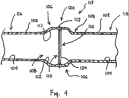
[0016] Fig. 4 is a side sectional view of a fused conduit made in accordance
with one
einbodiment of a method according to the principles of the present invention;
[0017] Fig. 5 is a side view of a fused conduit made in accordance with
another
embodiment of a method according to the principles of the present invention;
[0018] Fig. 6 is a side sectional view of a conduit in an intennediate step of
manufacture in
one embodiment according to the principles of the present invention; and
[0019] Fig. 7 is a side sectional view of a conduit in an intei-lnediate step
of manufacture in
anotlier einbodiment according to the principles of the present invention.
DESCRIPTION OF THE PREFERRED EMBODIMENTS
[0020] For purposes of the description hereinafter, the terms "upper",
"lower", "right",
"left", "vertical", "horizontal", "top", "bottom", "lateral", "longiti.idinal"
and derivatives
-4-
CA 02683066 2009-10-06
WO 2008/128154 PCT/US2008/060192
thereof shall relate to the invention as it is oriented in the drawing
figures. However, it is to
be understood that the invention may assulne various alteniative variations
and step
sequences, except where expressly specified to the contrary. It is also to be
understood that
the specific devices and processes illustrated in the attached drawings, aiid
described in the
following specification, are simply exemplary einbodiments of the invention.
Hence, specific
dimensions and other physical characteristics related to the einbodiments
disclosed herein are
not to be considered as limiting.
[0021] Various nuinerical ranges are disclosed in this patent application.
Because these
ranges are contimious, they include every value between the minizntun and
maxixnum values.
Unless expressly indicated otherwise, the various nuinerical ranges specified
in this
application are approximations.
[0022] I1i one aspect of the present invention, and as illustrated in various
einbodiinents in
Figs. 1-5, a conduit 100 is provided. In one preferred and non-limiting
elnbodiment, the
conduit 100 is a linearly extending length of conduit 100, both prior to and
after the fusion
process described hereinafter. However, the presently-invented conduit 100 and
method of
manufacturing this conduit 100 may be used to provide a variety of different
forms,
aiTangeinents, shapes, sizes and configurations. For exalnple, the conduit 100
(or sections
thereof) may be in the fonn of a substantially linear length of conduit, an
elbow, a cuive, a
non-linear length of conduit, etc. Accordingly, the present invention is not
limited to any
specific shape, configuration, geometric fonn, etc. Furtlier, and as discussed
above, the term
"conduit" is interchangeable with the tenn "pipe," and nonnally refers to a
tubular body with
a circular cross section. However, any shape, configuration or geometric cross
section is
envisioned as within the context and scope of the present application.
[0023] In one preferred and non-limiting einbodiment, and as best seen in Fig.
1, the
conduit 100 includes a linear portion 102 having a linear portion inside
diameter 104. In
addition, the conduit 100 includes at least one bell portion 106 having a
first end 108 and a
second end 110. The bell portion 106 has a bell portion inside dialneter 112,
a.nd the
dialneter 112 is greater at the second end 110 of the bell portion 106 than at
the first end 108
of the bell portion 106. Further, and in one prefelTed and non-limiting
einbodiment, the
inside diameter 112 at the first end 108 is substantially the same as the
inside diaineter 104 of
the linear portion 102, and gradually increases towards an intermediate
portion 109 of the bell
portion 106. From this intennediate portion 109 to the second elid 110 of the
bell portion
106, the inside diameter 112 reinains substantially constant, thereby
providing a square face
at the second end 110 of the bell portion 106. It is this changed inside
diaineter 112 that
-5-
CA 02683066 2009-10-06
WO 2008/128154 PCT/US2008/060192
provides or fonns the "bell" shape of the bell portion 106 of the conduit 100.
lii addition,
when used in comlection with a conduit 100 or bell portion 106 that does not
include a
circular cross section, at least one inside dimension, e.g., the width, at the
second end 110 of
the bell portion 106 is greater than the saine inside dimension, e.g., the
width, at the first end
108 of the bell portion 106.
[0024] Wliile only illustrated on one end 115 of the conduit 100 in Fig. 1, it
is envisioned
that the bell portion 106 may be formed, located or positioned on both
terininal ends 114, 115
of the conduit 100. Such an arrangement is illustrated in Fig. 2. In addition,
by placing the
bell portion 106 on each end 114, 115 of the conduit 100, lnultiple lengths of
such conduit
100 may be fiised together, as discussed in detail hereinafter. In addition,
and as discussed
above and illustrated in Fig. 3, any desired shaped or forined conduit 100 may
be fused
together using the bell portions 106 situated at one or both ends 114, 115 of
the conduit 100.
For exainple, the conduit 100 of Fig. 3 is in the fonn of an elbow with a bell
portion 106
located at each tenninal end 114, 115.
[0025] As discussed above, and in one preferred and non-limiting einbodiment,
the conduit
100 and/or its components, e.g., the linear portion 102, the bell portion 106,
etc., are
maalufachlred from a polyvinyl chloride composition. In particular, the
conduit 100 and/or
any portion 102, 106 of the conduit 100 may be manufactured by extruding a
polyvinyl
chloride composition in a known extrusion process. Further, any n.umber of
compositions
may be used in order to maximize the ability to successfully fuse sections of
conduit 100
together, as discussed in more detail hereinafter.
[0026] In another aspect, the present invention is directed to a method for
fiising a first
conduit section 116 to a second conduit section 118. As discussed above, each
conduit
section 116, 118 includes at least one bell portion 106, and may (but not
necessarily) include
the linear portion 102. hl one prefeiTed and non-limiting einbodiment, the
first conduit
section 116 and the second conduit section 118 are fiised as follows. First,
the second end
110 of the bell portion 106 of the first conduit section 116 is positioned in
an opposing
relationship with the second end 110 of the bell portion 106 of the second
conduit section
118. Next, the second ends 110 of the bell portions 106 of each conduit
section 116, 118 are
aliglled. At least a portion of the second ends 110 of each of the bell
portions 106 of the
conduit sections 116, 118 are melted. Further, the melted ends 110 are engaged
with each
other, and pressure is maintained between the engaged ends 110, thereby
creating a fused
conduit 119 having a fused j oint area 120. In one embodiment, the pressure
and engagement
of the melted ends 110 is maintained until the melted ends 110 of each conduit
section 116,
-6-
CA 02683066 2009-10-06
WO 2008/128154 PCT/US2008/060192
118 are cooled sufficiently to provide the fiised conduit 119 having the fused
joint area 120 of
a desired strength.
[0027] A fi.utlier exainple of a fiised conduit 119 using the fusion method of
the present
invention is illustrated in Fig. 5. As seen in this non-limiting embodilnent,
the first conduit
section 116 is in the form or shape of a curve, and the second conduit section
118 is in the
fonn or shape of an elbow. Further, wliile the second conduit section 118
includes a bell
portion 106 on each terininal end 114, 115, the first con.duit section 116 has
the bell portion
106 located on only the second tenniilal end 115. Fusion of the first tenninal
end 114 (non-
bell portion end) of the first conduit section 116 to a subsequent length,
piece or section of
conduit or pipe witliout a bell portion 106 located tliereon may be
accomplished according to
the fiision process and method shown and described in U.S. Paten.t No.
6,982,051.
[0028] As discussed above, and in one preferred and non-limiting embodiment,
the first
conduit section 116, the second conduit section 118, the linear portion 102 of
the first conduit
section 116, the linear portion 102 of the second conduit section 118, the
bell portion 106 of
the first conduit section 116 and/or the bell portion 106 of the second
conduit section 118
may be manufactured from a polyvinyl chloride composition. However, the first
conduit
section 116 and the second conduit section 118 may be extrLided from a variety
of
thernnoplastic materials, e.g., plastic, polyethylene, hig11 density
polyethylene, etc, where the
thennoplastic material exhibits or includes properties sufficient to pennit
fiision of the bell
portion 106 of the first con.duit section 116 to the bell portion 106 of the
second conduit
section 118. Therefore, and as discussed above in conn.ection with Figs. 1-5,
one or both of
the first conduit section 116 and the second conduit section 118 includes a
bell portion 106
positioned or forlned on one or botli ends 114, 115 of the conduit section
116, 118.
[0029] In order to fuse additional lengths of conduit, the process may be used
with
subsequent sections of conduit 100 having the bell portion 106 on at least one
tenninal end
114, 115. Specifically, the positioning, aligning, melting and engaging steps
discussed above
can be used to continue adding subsequent lengths or sections of conduit 100
(regardless of
shape or size), thereby creating a longer, fused conduit system 119. It should
be noted,
however, that the fiision process described above only necessarily requires
the melting and
engaging step in order to provide the fused conduit system 119 and the fi.ised
joint area 120.
Ftuther, since these conduit sections 116, 118 may be formed in a variety of
shapes, sizes,
fonrn.s, configurations, etc, and wlzen fused togetlier at the second end 110
of the respective
bell portion 106 of each conduit section 116, 118 (and fiirther or subsequent
conduits 100), a
-7-
CA 02683066 2009-10-06
WO 2008/128154 PCT/US2008/060192
fiised conduit system 119 is provided. This fused conduit system 119 can be
used to create
any desired lengtlz conduit, casing, pipeline or otlier above groulid or
undergroiuid system.
[0030] hi one preferred and non-limiting elnbodiment, the second end 110 of
one or both
of the bell portions 106 may be faced prior to the aligiunent step.
Specifically, using a facing
mechanism (as described in U.S. Patent No. 6,982,051), a.nd prior to melting
and engaging
the second ends 110 of the bell portions 106, provides parallel, smootll,
flush and opposing
edges. In particular, the facing mechanism (i.e., the facing blade or
implement) grinds or
faces the ends 110 Luztil a minimal distance exists between faced ends 110
(nonnally the
tliiclaless of the facing blade or iinplement), or it reaches predetennined
stops associated with
the devices clainping or holding these ends 110.
[0031] Still fiu-ther, and as discussed above in coiuiection with the fusion
of two opposing
conduit sections 116, 118, the melting step of the present einbodiment may
include the
simultaneous heating of both the second end 110 of the bell portion 106 of the
first conduit
116 aiid the second end 110 of the bell portion 106 of the second conduit 118.
In order to
provide appropriate heating and melting of the second ends 110, multiple heat
zones can be
provided and applied to the second ends 110 of the bell portion.s 106 of the
conduits 116, 118.
In particular, heating plates (as described in U.S. Patent No. 6,982,051) may
be used to
provide such zone heating, e.g., variance in temperature of various portions
of the heating
surface, for example, the upper and lower surface. This provides a more
unifonn melting of
the ends 110, due to the natural physics of the heating process.
[0032] After the conduits 116, 118, and in particular the bell portions 106 of
the conduits
116, 118, are fiised, an outer bead 122 and inner bead 124 are fonned. Again,
such beads
122, 124 are formed since the second end 110 of the bell portion 106 of each
conduit 116,
118 is heated and at least partially melted. Upon engaging and pressing the
ends 110
together, the melted material is pressed and fonns these beads 122, 124. See,
e.g., Fig. 4. It
is the potentially detrimental effects of these formed beads 122, 124 that the
above-descl-ibed
conduit 100, 116, 118, 119 and fusion method minimize or obviate, with
particular usefulness
in comiection with conduit used to house wiring, cables, etc.
[0033] In another preferred and non-limiting embodiment, sufficient pressure
is maintained
and subsequent cooling perinitted at the second ends 110 of the bell portions
106 of each
conduit section 116, 118 to fonn a fused joint area 120 of a desired strength.
In addition, aazd
in order to provide a fused joint area 120 exhibiting at least 50% of the
tensile strength (or
even substantially the same strength) as one or both of the conduit sections
116, 118, any of
the following paraineters may be selected and used during the fusion process:
engageinent
-8-
CA 02683066 2009-10-06
WO 2008/128154 PCT/US2008/060192
interfacial pressure, engagement gauge pressure, engagement time, heating
interfacial
presstue, heating gauge pressure, heating teinperature and/or heating time.
For exainple, in
one einbodiment, the engageinent gauge pressure is calculated using the
following formula:
n(ODZ-ID2)
MGp = 4 x Ip
Ca
where MGp is maclline gauge pressure, n is 3.1416 circle fonnula, OD2 is
outside diameter in
inches squared, ID 2 is inside dialneter of the linear portion in inches
squared, Ip is interfacial
pressure, and Ca is the cylinder area of machine in square inches. Further,
the "OD" and
"ID" referenced are either: the outside and inside diameter for the conduit or
pipe without the
bell portion 106; or those of the bell portion 106, itself. As the cross
sectional area will
preferably be the sa.ine for each, either sets of dialneters can be used. In
addition, if the bell
portion 106 includes a different cross section, e.g., a square shape, th.is
formula may be
modified by substituting "cross sectional area of the end of the bell portion"
for the fraction
included in the nlunerator of the fraction. Iii another einbodiment, the
engagement interfacial
pressure is between about 50 psi and about 250 psi, the heating pressure is
between about 5
psi a.n.d about 50 psi, and the time period between the heating and melting
and the engaging is
up to about 10 seconds.
[0034] By using the above-discussed polyvinyl chloride composition, as well as
the bell
portions 106 of the conduit 100, a fi,ised conduit system 119 and fused joint
area 120 are
created. Due to the shape of the fused bell portions 106, the imzer bead 124
that is forined
during the fusion process does not encroach into the area defined by the
linear portion inside
diameter 104 (or the "non-bell" portions of the conduit 100). Other dimensions
may be
modified and maximized for effective use, e.g., general flow characteristics,
intended use of
the fiised conduit 119, etc. Such dimensions, e.g., the length of the bell
portion 106 and the
offset from the linear portion 102 of the conduit 100, may be set to keep the
imier bead 124
out of the area defined by the linear portion inside diameter 104, as well as
to lninimize the
overall, fiised bell portion 106 length. In particular, by minimizing the
overall bell portion
106 lengtli, the ability of wire or fiber optic cable to sag into the bell
portion 106 (thereby
jeopardizing the integrity of any protective coating on the wire or cable by
touching or
rubbing against the imzer bead 124) is minimized or eliminated. Still further,
the length of the
bell portion 106 and the offset may also be varied for effective utilization
aiid implementation
in certain specialized or necessary applications.
-9-
CA 02683066 2009-10-06
WO 2008/128154 PCT/US2008/060192
[0035] As discussed, and in one preferred and non-limiting einbodiment, the
conduit 100,
116, 118 (or arly part thereof) may be maalufactured using a polyvinyl
chloride colnposition.
According to this embodiment, and as illustrated in Fig. 6, in manufacturing
the conduit 100,
a linear section 126 of conduit is provided, and this linear section 126
includes at least one
tenninal end 128. It should be noted that this linear section 126 may be at
the terminal end
128 of any size, shape or configuration of conduit 100, e.g., an elongated,
linear lengtli, an
elbow, a curve, etc. Next, the termiiial end 128 is engaged with a shaped
malidrel 130, which
bears against the terininal end 128 and defonns the linear section 126,
thereby folming the
above-discussed bell portion 106 at the tenninal end 128 of the linear section
126.
Accordingly, the lnandrel 130 is sized and shaped so as to iinpai-t the
appropriate fonn,
contour, shape and size of the desired bell portion 106 to the linear section
126 of the conduit
100.
[0036] The present invention contemplates various ways of fonning the bell
portion 106.
hi one prefen ed and non-limiting einbodiment, and as illustrated in Fig. 6,
prior to engaging
the tenninal end 128 against the shaped mandrel 130, the terlninal end 128 is
heated.
Specifically, the tenninal end 128 is heated to a teinperattue sufficient to
allow the end 128 to
fonn and take the shape of the shaped mandrel 130. For exainple, the tenninal
end 128 may
already be at or near a sufficient temperature after extrusion, such that the
fonnation of the
bell portion 106 may occur during, or ilninediately after, the extrusion
process and before
cooling. li1 another prefeiTed aa.ld non-limiting embodiment, and as opposed
to heating the
tenninal end 128 of the linear section 126, the shaped mandrel 130 is heated
to a temperature
appropriate to at least partially melt the tenninal end 128 of the conduit
100. Such an
arrangeinent is illustrated in Fig. 7. lii order to allow the shaped maiidrel
130 to achieve the
desired melting teinperature, an appropriate heat source 132 may be provided.
Of course, this
heat source 132 may be controlled to a specified temperature range in order to
maximize the
efficiency and effectiveness of the heating process.
[0037] After the bell portion 106 is fonned at the teiminal end 128 of the
conduit 100, this
newly-fonned bell portion 106 is pennitted to cool. Finally, after the bell
pol-tion 106 has
cooled and cured, it is disengaged from the shaped mandrel 130: This saine
lnanufacturing
teclnzique and process may be used on each terminal end 128 of the linear
section 126, as
needed. In this maluler, the conduit 100 is fonned with a bell portion 106 on
one or both of
the tenninal ends 128.
[0038] Wliile specific methods for manufacturing the inventive conduit 100
have been
discussed, any mamler of positioning or forming the bell portion 106 on the
conduit 100 is
-10-
CA 02683066 2009-10-06
WO 2008/128154 PCT/US2008/060192
envisioned. For example, as opposed to using the shaped mandrel 130, shaped
sleeves,
fonns, molds and other alTangelnents may be used. For example, the bell
portion 106 may be
fonned on the conduit 100 during the initial extrusion or molding process, or
in a variety of
methods lalown in the art for preparing and manufacturing shaped plastic
products.
[0039] hi anotlier preferred and non-limiting elnbodiinent, the bell portion
106 is fomled
on-site or in the field using transportable and/or portable (mobile)
equipment. For exainple, a
fi.ision apparatus, such as the apparatus described in U.S. Patent No.
6,982,051 can be
modified for use in fonning the bell portion 106 on a linear length of
extltiided conduit 100.
In addition, the shaped mandrel 130, e.g., in the form of a modified heater
mechanism, heat
plate, etc., may be used oii or in connection with this fusion apparatus.
Accordingly, the bell
portion 106 can be fonned on one or botli ends of the conduit 100 on an "as-
needed" basis in
the field.
[0040] The present invention is useful in connection with a variety of
applications in both
underground and above ground installations. For exasnple, the conduit 100,
fi.ised conduit
system 119 and metllod of fiising of the present invention may be used in
siti,iations where,
according to the prior art and in order to transport and insert a liner
conduit witliin the host
conduit, the liner conduit must be manufactured in sections or portions, which
are typically
inuch shorter in length than the final and intended liner conduit length. In
particular, the
condult sections 116, 118 may be fused at the installation site according to
the cllanging
needs and requireinents of the lining process. Still fi.u-ther, the conduit
100, fused conduit
system 119 and method of fiising of the present invention may be utilized in
sliplining
applications, whereiii a slightly smaller diameter fiised conduit is inserted
into a larger pipe
that is in need of rehabilitation or that is used for conveying or calTying
other materials.
Anotller variation of the slipline process for conduit entails the pulling of
multiple conduits
simultaneously in a"bundle" that result in inultiple conduits within a casing
or host pipe.
[0041] The conduit 100 and fused conduit system 119 may be implemented in
various
other applications, wherein the fused joint is used in comzection with a
horizontal directional
drilling process. According to this process, a pilot hole is drilled in the
ground and can be
steered in a precise maiuzer to control elevation and aligiunent. After the
pilot hole is
colnplete, the drill hole is reamed to a larger diarneter and filled with
drill mud to hold the
larger hole open and provide lubrication. The conduit 100, fiised conduit
systein 119 or
bundled conduit is then pulled through the dri11 mud resulting in a conduit or
conduit bundle
in place.
-11-
CA 02683066 2009-10-06
WO 2008/128154 PCT/US2008/060192
[0042] Further, the fused conduit systeln 119 is useful in a pipe bursting
application. Pipe
bursting uses a cutter head, e.g., a large hydraulic or pneuinatic cutter
head, to brealc apart old
pipe and force the pieces into the surrounding soil. This allows a new pipe or
pipe bundles of
equal or larger dialneter to be pulled into the resultant void. This process
is often used where
the new line capacity inust be increased. Also, the conduit 100 and fused
conduit system 119
is equally usefiil in a direct-bury application, where an at least partially
open conduit hole is
created, and the fiised conduit system 119 inserted or positioned in the
conduit hole. Another
variation of a direct-bury application entails the use of a plow to cut a slit
aiid pipe opening in
the ground, and the conduit 100 or fused conduit system 119 is pulled in
behind. This is
typically a simultaneous process. The conduit 100, fiised conduit systein 119,
and method of
fi.ising of the present invention cali be effectively implemented and used in
a.ny number of
applications and installations, and all such applications and installations
should be considered
within the context and scope of the present invention.
[0043] In this maluier, this aspect of the present invention eliminates the
potential impact
of the imler bead 124 fonned during the fiision process. In addition, this
impact is minimized
and eliminated witliout adding additional process steps, costs or time to the
fi.ision and
installation process. h1 this mamler, any fiision process that occurs at the
worlc site is not
altered, and the overall length of time to engage in the process is not
lengthened. In addition,
this aspect of the present invention removes the need for any de-beading
equipment, and the
fi.ised conduit system 119 and fused joint area 120 do not exhibit the above-
discussed
drawbacks associated with mechanical or solvent welded joints.
[0044] Although the invention has been described in detail for the pulpose of
illustration
based on what is ctuTently considered to be the most practical and preferred
ernbodiments, it
is to be understood that such detail is solely for that purpose and that the
invention is not
limited to the disclosed elnbodiments, but, on the contrary, is intended to
cover modifications
and equivalent arrangements that are withi.n the spirit and scope of the
appended claims. For
exainple, it is to be understood that the present invention contemplates that,
to the extent
possible, one or more features of any embodiment can be combined with one or
more features
of any other einbodiment.
-12-