Sélection de la langue

Search

Sommaire du brevet 2683297 

Énoncé de désistement de responsabilité concernant l'information provenant de tiers

Une partie des informations de ce site Web a été fournie par des sources externes. Le gouvernement du Canada n'assume aucune responsabilité concernant la précision, l'actualité ou la fiabilité des informations fournies par les sources externes. Les utilisateurs qui désirent employer cette information devraient consulter directement la source des informations. Le contenu fourni par les sources externes n'est pas assujetti aux exigences sur les langues officielles, la protection des renseignements personnels et l'accessibilité.

Disponibilité de l'Abrégé et des Revendications

L'apparition de différences dans le texte et l'image des Revendications et de l'Abrégé dépend du moment auquel le document est publié. Les textes des Revendications et de l'Abrégé sont affichés :

  • lorsque la demande peut être examinée par le public;
  • lorsque le brevet est émis (délivrance).
(12) Brevet: (11) CA 2683297
(54) Titre français: FLASQUE LATERAL ET MOTEUR A ROTOR EXTERNE Y FAISANT APPEL
(54) Titre anglais: END COVER AND EXTERNAL ROTOR MOTOR USING THE SAME
Statut: Accordé et délivré
Données bibliographiques
(51) Classification internationale des brevets (CIB):
  • H02K 05/04 (2006.01)
  • H02K 01/06 (2006.01)
(72) Inventeurs :
  • LU, CHUPING (Chine)
(73) Titulaires :
  • ZHONGSHAN BROAD-OCEAN MOTOR CO., LTD.
(71) Demandeurs :
  • ZHONGSHAN BROAD-OCEAN MOTOR CO., LTD. (Chine)
(74) Agent: MILTONS IP/P.I.
(74) Co-agent:
(45) Délivré: 2013-12-17
(22) Date de dépôt: 2009-10-22
(41) Mise à la disponibilité du public: 2010-04-23
Requête d'examen: 2009-12-21
Licence disponible: S.O.
Cédé au domaine public: S.O.
(25) Langue des documents déposés: Anglais

Traité de coopération en matière de brevets (PCT): Non

(30) Données de priorité de la demande:
Numéro de la demande Pays / territoire Date
200820202461.7 (Chine) 2008-10-23

Abrégés

Abrégé français

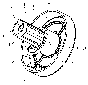
Couvercle de bout pour moteur à rotor externe. Le moteur à rotor externe comprend un noyau de stator ayant un trou central et le couvercle de bout comprend un corps, une portion de connexion cylindrique et de multiples barres en saillie ayant une surface supérieure en forme d'arc. La portion de connexion cylindrique s'étend du centre du corps et passe par le trou central du noyau de stator. Les barres en saillie sont placées sur la surface externe de la portion de connexion cylindrique et s'étendent dans une direction axiale. La surface supérieure en forme d'arc de la barre en saillie concorde avec la paroi intérieure du trou central du noyau de stator. Le couvercle de bout concorde avec le noyau de stator et ne nécessite aucun traitement supplémentaire après la coulée sous pression réduisant ainsi les coûts de production et empêchant les morceaux d'aluminium d'entrer dans le stator.


Abrégé anglais

An end cover for an external rotor motor. The external rotor motor has a stator core having a center hole, and the end cover including a body, a cylindrical connecting portion, and multiple protruding bars each having an arc-shaped top surface. The cylindrical connecting portion is extended from the center of the body and received in the center hole of the stator core, the protruding bars are disposed on outer surface of the cylindrical connecting portion and extended in an axial direction, and the arc- shaped top surface of the protruding bar is fit with inner wall of the center hole of the stator core. The end cover is accurately fit with a stator core, requires no further processing after die--casting and thus reducing production cost, and is capable of preventing aluminum scraps from entering a stator.

Revendications

Note : Les revendications sont présentées dans la langue officielle dans laquelle elles ont été soumises.


CLAIMS
1. An end cover for an external rotor motor, said external rotor motor
comprising a
stator core having a center hole, and said end cover comprising:
a body;
a cylindrical connecting portion; and
multiple protruding bars each having an arc-shaped top surface;
wherein:
said cylindrical connecting portion is extended from the center of said
body and received in said center hole of said stator core;
said protruding bars are disposed on an outer surface of said cylindrical
connecting portion and extended in an axial direction;
said arc-shaped top surface of said protruding bar surface fits with an
inner wall of said center hole of said stator core;
a groove is formed between adjacent protruding bars;
multiple flanges are extended from a lower part of said body towards the
center; and
each flange is received in each groove.
2. The end cover of claim I, wherein:
said groove comprises a front part and a rear part;
said front part of said groove and said rear part of said groove are parallel
to a central axis of said cylindrical connecting portion;
the perpendicular distance between said front part of said groove and the
central axis of said cylindrical connecting portion is smaller than the
6

perpendicular distance between said rear part of said groove and the central
axis
of said cylindrical connecting portion; and
a width of said front part of said groove is greater than a width of said rear
part of said groove.
3. The end cover of claim 1 or 2, wherein a bottom surface of said groove
is arc-
shaped.
4. The end cover of any one of claims 1 to 3, wherein a cross section of a
lower part
of said body is annular.
5. The end cover of any one of claims 1 to 4, wherein one end of said
stator core
abuts against a top surface of said flange.
6. The end cover of any one of claims 1 to 5, wherein a slot is formed
between
adjacent flanges and operates to receive aluminum scraps.
7. The end cover of claim 6, wherein said slot is disposed at a bottom end
of said
protruding bar.
8. The end cover of any one of claims 1 to 7, wherein:
said protruding bar comprises a front part and a rear part;
said front part of said protruding bar and said rear part of said protruding
bar are parallel to a central axis of the cylindrical connecting portion;
the perpendicular distance between said front part of said protruding bar
and the axis of said cylindrical connecting portion is shorter than the
perpendicular distance between said rear part of said protruding bar and the
axis
of said cylindrical connecting portion; and
7

a width of said front part of said protruding bar is smaller than a width of
said rear part of said protruding bar.
9. The end cover of any one of claims 1 to 8, wherein a pair of positioning
ribs are
disposed on the outer surface of said cylindrical connecting portion and
extended
in the axial direction.
10. The end cover of claim 9, wherein a pair of positioning grooves is
disposed on
both sides of said center hole of said stator core.
11. The end cover of claim 10, wherein each positioning rib is received in
each
positioning groove thereby preventing said stator core from rotating axially.
12. An external rotor motor, comprising:
a stator core having a center hole; and
an end cover, comprising:
a body;
a cylindrical connecting portion; and
multiple protruding bars, each protruding bar having an arc-shaped
top surface;
wherein:
said cylindrical connecting portion is extended from a center of said body
and received in said center hole;
said protruding bars are disposed on an outer surface of said cylindrical
connecting portion and extended in an axial direction;
said arc-shaped top surface of said protruding bar surface fits with an
inner wall of said center hole of said stator core;
8

a groove is formed between adjacent protruding bars;
multiple flanges are extended from a lower part of said body to the center;
and
each flange is received in each groove.
13. The external rotor motor of claim 12, wherein a pair of positioning
grooves is
disposed on both sides of said center hole of said stator core.
14. The external rotor motor of claim 13, wherein a pair of positioning
ribs are
disposed on the outer surface of said cylindrical connecting portion and
extended
in the axial direction.
15. The external rotor motor of claim 14, wherein each positioning rib is
received in
each positioning groove thereby preventing said stator core from rotating
axially.
9

Description

Note : Les descriptions sont présentées dans la langue officielle dans laquelle elles ont été soumises.


CA 02683297 2012-11-08
END COVER AND EXTERNAL ROTOR MOTOR USING THE SAME
DESCRIPTION
[0001] The invention relates to an end cover and for an external rotor motor.
[0002] A conventional motor comprises a stator, motor coil, along with a
stator core and an end
cover fit with each other. However, there are several problems with the motor:
fitting precision is
limited since the end cover cannot be directly die-casted and accurately fit
with the stator core,
and thus further processing is required, which increases production cost;
moreover, aluminum
scraps generated during the fitting process often enter one end of the motor
coil and an air gap of
the stator, and affect product quality.
[0003] In view of the above-described problem, it is one objective of the
invention to provide an
end cover that is accurately fit with a stator core, requires no further
processing after die-casting
and thus reducing production cost, and is capable of preventing aluminum
scraps from entering a
stator.
In one aspect of the present invention, there is provided a An end cover for
an external rotor
motor, the external rotor motor comprising a stator core having a center hole,
and the end cover
comprising: a body; a cylindrical connecting portion; and multiple protruding
bars each having
an arc-shaped top surface; wherein: the cylindrical connecting portion is
extended from the
center of the body and received in the center hole of the stator core; the
protruding bars are
disposed on an outer surface of the cylindrical connecting portion and
extended in an axial
direction; the arc-shaped top surface of the protruding bar surface fits with
an inner wall of the
center hole of the stator core; a groove is formed between adjacent protruding
bars; multiple
flanges are extended from a lower part of the body towards the center; and
each flange is
received in each groove.
In another aspect of the present invention, there is provided an external
rotor motor, comprising a
stator core having a center hole; and an end cover, comprising: a body; a
cylindrical connecting
portion; and multiple protruding bars, each protruding bar having an arc-
shaped top surface;
wherein: the cylindrical connecting portion is extended from a center of the
body and received in
the center hole; the protruding bars are disposed on an outer surface of the
cylindrical connecting
1

CA 02683297 2012-11-08
portion and extended in an axial direction; the arc-shaped top surface of the
protruding bar
surface fits with an inner wall of the center hole of the stator core; a
groove is formed between
adjacent protruding bars; multiple flanges are extended from a lower part of
the body to the
center; and each flange is received in each groove.
[0004] It is another objective of the invention to provide a motor having an
end cover that is
accurately fit with a stator core, requires no further processing after die-
casting and thus reducing
production cost, and is capable of preventing aluminum scraps from entering a
stator.
[0005] To achieve the above objectives, in accordance with one embodiment of
the invention,
provided is an end cover for an external rotor motor, the external rotor motor
comprising a stator
core having a center hole, and the end cover comprising a body, a cylindrical
connecting portion,
and multiple protruding bars each having an arc-shaped top surface. The
cylindrical connecting
portion is extended from the center of the body and received in the center
hole of the stator core,
the protruding bars are disposed on outer surface of the cylindrical
connecting portion and
extended in an axial direction, and the arc-shaped top surface of the
protruding bar is fit with
inner wall of the center hole of the stator core.
[0006] In a class of this embodiment, a groove is formed between adjacent
protruding bars.
1A

CA 02683297 2009-10-22
. ,
[0007] In a class of this embodiment, a width of a front part of the groove is
greater than
that of a rear part thereof.
[0008] In a class of this embodiment, a bottom surface of the groove is arc-
shaped.
[0009] In a class of this embodiment, a cross section of a lower part of the
body is
annular.
[0010] In a class of this embodiment, multiple flanges are extended from the
lower part
of the body to a center thereof.
[0011] In a class of this embodiment, the flange is received in the groove.
[0012] In a class of this embodiment, one end of the stator core abuts against
a top
surface of the flange.
[0013] In a class of this embodiment, a slot is formed between adjacent
flanges and
operates to receive aluminum scraps.
[0014] In a class of this embodiment, the slot is disposed at the bottom of
the protruding
bar.
[0015] In a class of this embodiment, a width of a front part of the
protruding bar is less
than that of a rear part thereof.
[0016] In a class of this embodiment, a pair of positioning ribs are disposed
on the outer
surface of the cylindrical connecting portion and extended in an axial
direction.
[0017] In a class of this embodiment, a pair of positioning grooves are
disposed on both
sides of the center hole of the stator core.
[0018] In a class of this embodiment, the positioning rib is received in the
positioning
groove whereby preventing the stator core from rotating axially.
[0019] In accordance with one embodiment of the invention, provided is an
external rotor
motor, comprising a stator core having a center hole, and an end cover,
comprising a
body, a cylindrical connecting portion, and multiple protruding bars each
having an arc-
shaped top surface. The cylindrical connecting portion is extended from the
center of the
body and received in the center hole of the stator core, the protruding bars
are disposed
on outer surface of the cylindrical connecting portion and extended in an
axial direction,
2

CA 02683297 2009-10-22
and the arc-shaped top surface of the protruding bar is fit with inner wall of
the center
hole of the stator core.
[0020] In a class of this embodiment, a pair of positioning grooves are
disposed on both
sides of the center hole of the stator core.
[0021] In a class of this embodiment, a pair of positioning ribs are disposed
on the outer
surface of the cylindrical connecting portion and extended in an axial
direction.
[0022] In a class of this embodiment, the positioning rib is received in the
positioning
groove whereby preventing the stator core from rotating axially.
[0023] Advantages of the invention comprise: 1) since the arc-shaped top
surface of the
to protruding bar is fit with inner wall of the center hole of the stator
core, high fitting
precision is ensured, and no further processing is required, which reduces
production cost
and simplifies structure of the motor; 2) the groove formed between adjacent
protruding
bars operates as a taper face of the die-casting process, reduces difficulty
of die-casting,
simplifies a processing process, and does not generate aluminum scraps during
the fitting
process; 3) the flanges are received in the groove, which prevents aluminum
scraps
generated during the fitting process from affecting fitting precision, and
ensures that an
axial spacing dimension is accurate; 4) aluminum scraps generated by the
protruding bar
during the fitting process are received in the slot and cannot enter the
motor, which
improves safety of the motor; 5) a width of a front part of the protruding bar
is less than
that of a rear part thereof, which makes it convenient to be pressed and
improves fitting
strength between the protruding bar and the stator core; 6) a width of a front
part of the
groove is greater than that of a rear part thereof, which makes it convenient
for die
releasing, reduces production difficulty and ensures precision of die-casting
of the
protruding bar; 7) the top surface of the flange is flat and has no aluminum
scraps, and
therefore fitting precision between the flange and one end of the stator core
is high.
[0024] The invention is described hereinafter with reference to accompanying
drawings,
in which:
[0025] FIG. 1 is a schematic view of an end cover of an exemplary embodiment
of the
invention;
3

CA 02683297 2009-10-22
,
[0026] FIG. 2 is an enlarged view of a I portion of FIG. 1;
[0027] FIG. 3 is an enlarged view of a II portion of FIG. 1;
[0028] FIG. 4 is a top view of an end cover of an exemplary embodiment of the
invention;
[0030] FIG. 6 is a schematic view of an end cover fit with a stator core; and
[0031] FIG. 7 is a partial cross-sectional view of an end cover fit with a
stator core.
[0032] As shown in FIGS. 1-7, an end cover for an external rotor motor
comprises a
body 1, a cylindrical connecting portion 3, and multiple protruding bars 4.
of positioning grooves 10 are disposed on both sides of the center hole 11 of
the stator
core 2.
[0034] A cross section of a lower part of the body 1 is annular.
[0035] The cylindrical connecting portion 3 is extended from the center of the
body 1 and
[0036] The protruding bar 4 is disposed on outer surface of the cylindrical
connecting
portion 3 and extended in an axial direction, and has an arc-shaped top
surface. The arc-
shaped top surface of the protruding bar 4 is fit with inner wall of the
center hole 11 of
the stator core 2, and therefore high fitting precision is ensured and no
further processing
[0037] A width of a front part of the protruding bar 4 is less than that of a
rear part
thereof, which makes it convenient to be pressed and improves fitting strength
between
the protruding bar 4 and the stator core 2.
[0038] A groove 5 is formed between adjacent protruding bars 4, and a width of
a front
4

CA 02683297 2009-10-22
[0039] The groove 5 operates as a taper face of the die-casting process,
reduces difficulty
of die-casting, simplifies a processing process, and does not generate
aluminum scraps
during the fitting process.
[0040] Multiple flanges 7 are extended from the lower part of the body 1 to a
center
thereof and received in the groove 5. One end of the stator core 2 abuts
against a top
surface of the flange 7. The flange 7 prevents aluminum scraps generated
during the
fitting process from affecting fitting precision, and ensures that an axial
spacing
dimension is accurate. The top surface of the flange 7 is flat and has no
aluminum scraps,
and therefore fitting precision between the flange 7 and one end of the stator
core 2 is
high.
[0041] A slot 8 is formed between adjacent flanges 7 and disposed at the
bottom of the
protruding bar 4, and operates to receive aluminum scraps, and thus aluminum
scraps
cannot enter the motor, which improves safety of the motor
[0042] A pair of positioning ribs 9 are disposed on the outer surface of the
cylindrical
connecting portion 3 and extended in an axial direction. The positioning rib 9
is received
in the positioning groove 10 whereby preventing the stator core 2 from
rotating axially.
[0043] While particular embodiments of the invention have been shown and
described, it
will be obvious to those skilled in the art that changes and modifications may
be made
without departing from the invention in its broader aspects, and therefore,
the aim in the
appended claims is to cover all such changes and modifications as fall within
the true
spirit and scope of the invention.
5

Dessin représentatif
Une figure unique qui représente un dessin illustrant l'invention.
États administratifs

2024-08-01 : Dans le cadre de la transition vers les Brevets de nouvelle génération (BNG), la base de données sur les brevets canadiens (BDBC) contient désormais un Historique d'événement plus détaillé, qui reproduit le Journal des événements de notre nouvelle solution interne.

Veuillez noter que les événements débutant par « Inactive : » se réfèrent à des événements qui ne sont plus utilisés dans notre nouvelle solution interne.

Pour une meilleure compréhension de l'état de la demande ou brevet qui figure sur cette page, la rubrique Mise en garde , et les descriptions de Brevet , Historique d'événement , Taxes périodiques et Historique des paiements devraient être consultées.

Historique d'événement

Description Date
Représentant commun nommé 2019-10-30
Accordé par délivrance 2013-12-17
Inactive : Page couverture publiée 2013-12-16
Inactive : Taxe finale reçue 2013-08-26
Préoctroi 2013-08-26
Un avis d'acceptation est envoyé 2013-03-04
Lettre envoyée 2013-03-04
Un avis d'acceptation est envoyé 2013-03-04
Inactive : Approuvée aux fins d'acceptation (AFA) 2013-03-01
Modification reçue - modification volontaire 2012-11-08
Inactive : Dem. de l'examinateur par.30(2) Règles 2012-05-10
Demande publiée (accessible au public) 2010-04-23
Inactive : Page couverture publiée 2010-04-22
Lettre envoyée 2010-04-21
Inactive : CIB attribuée 2010-04-20
Inactive : CIB en 1re position 2010-04-20
Inactive : CIB attribuée 2010-04-20
Toutes les exigences pour l'examen - jugée conforme 2009-12-21
Exigences pour une requête d'examen - jugée conforme 2009-12-21
Requête d'examen reçue 2009-12-21
Inactive : Certificat de dépôt - Sans RE (Anglais) 2009-11-23
Demande reçue - nationale ordinaire 2009-11-19

Historique d'abandonnement

Il n'y a pas d'historique d'abandonnement

Taxes périodiques

Le dernier paiement a été reçu le 2013-10-11

Avis : Si le paiement en totalité n'a pas été reçu au plus tard à la date indiquée, une taxe supplémentaire peut être imposée, soit une des taxes suivantes :

  • taxe de rétablissement ;
  • taxe pour paiement en souffrance ; ou
  • taxe additionnelle pour le renversement d'une péremption réputée.

Les taxes sur les brevets sont ajustées au 1er janvier de chaque année. Les montants ci-dessus sont les montants actuels s'ils sont reçus au plus tard le 31 décembre de l'année en cours.
Veuillez vous référer à la page web des taxes sur les brevets de l'OPIC pour voir tous les montants actuels des taxes.

Titulaires au dossier

Les titulaires actuels et antérieures au dossier sont affichés en ordre alphabétique.

Titulaires actuels au dossier
ZHONGSHAN BROAD-OCEAN MOTOR CO., LTD.
Titulaires antérieures au dossier
CHUPING LU
Les propriétaires antérieurs qui ne figurent pas dans la liste des « Propriétaires au dossier » apparaîtront dans d'autres documents au dossier.
Documents

Pour visionner les fichiers sélectionnés, entrer le code reCAPTCHA :


Pour visualiser une image, cliquer sur un lien dans la colonne description du document. Pour télécharger l'image (les images), cliquer l'une ou plusieurs cases à cocher dans la première colonne et ensuite cliquer sur le bouton "Télécharger sélection en format PDF (archive Zip)" ou le bouton "Télécharger sélection (en un fichier PDF fusionné)".

Liste des documents de brevet publiés et non publiés sur la BDBC .

Si vous avez des difficultés à accéder au contenu, veuillez communiquer avec le Centre de services à la clientèle au 1-866-997-1936, ou envoyer un courriel au Centre de service à la clientèle de l'OPIC.


Description du
Document 
Date
(aaaa-mm-jj) 
Nombre de pages   Taille de l'image (Ko) 
Description 2009-10-21 5 232
Abrégé 2009-10-21 1 20
Revendications 2009-10-21 3 77
Dessins 2009-10-21 7 107
Dessin représentatif 2010-03-28 1 12
Description 2012-11-07 6 269
Revendications 2012-11-07 4 100
Paiement de taxe périodique 2024-06-23 2 63
Certificat de dépôt (anglais) 2009-11-22 1 155
Accusé de réception de la requête d'examen 2010-04-20 1 177
Rappel de taxe de maintien due 2011-06-22 1 114
Avis du commissaire - Demande jugée acceptable 2013-03-03 1 163
Correspondance 2013-08-25 3 65