Note : Les descriptions sont présentées dans la langue officielle dans laquelle elles ont été soumises.
CA 02683829 2009-10-14
PCT/EP2008/054263 - 1 -
2008P06681WOUS
Description
Lighting system with a flat lamp and a frame
Technical Field
The invention is based on a lighting system with a frame
and a flat lamp arranged therein.
Such lighting systems are used for a wide variety of
lighting tasks, in particular also for luminaires in
general lighting and for backlighting of liquid crystal
displays (LCDs), also referred to as backlight units
(BLUs). For backlighting tasks, in particular large-format
LCD television sets can be cited which have attracted
increasing attention in recent times.
The term "flat lamp" is in this case intended to mean
lamps, in particular fluorescent lamps, with a flat
geometry which emit white or colored light and, for
special applications, also UV light. The flat geometry in
this case does not exclude the possibility of, for
example, the front side of the flat lamp which is intended
for the light emission having a structure, for example
being corrugated or ribbed. The lamp vessel of the flat
lamp therefore does not necessarily need to be formed from
planar glass plates.
In addition to conventional flat lamps with mercury and/or
mobile gas fill, the invention is in particular also aimed
at flat lamps of the dielectric barrier discharge lamp
type. With this lamp type, either the electrodes of one
polarity or else all of the electrodes, i.e. the
electrodes of both polarities, are separated from the
discharge by means of a dielectric layer
CA 02683829 2009-10-14
PCT/EP2008/054263 - 2 -
2008P06681W0US
(dielectrically impeded discharge on one or two sides).
Such electrodes are also referred to below as "dielectric
electrodes" for short. In addition, it should also be
clarified that the dielectric layer does not need to be a
layer which is applied to an electrode specifically for
this purpose, but can also be formed by a discharge vessel
wall, for example, if the typically strip-like or linear
electrodes are arranged on the outer side of a discharge
vessel wall or within the wall.
Flat lamps of the dielectric barrier discharge lamp type
has proven to be particularly efficient flat light sources
if they are operated using the pulsed operating method
described in US 5,604,410 and are therefore particularly
well suited for use in a luminaire or a backlight unit.
Prior Art
Documents EP 1 600 808 Al has disclosed a lighting system
with a flat lamp. Therein, the flat lamp is inserted into
a housing with a rear wall and a peripheral side wall. A
likewise peripheral frame which has been plugged onto the
side wall fixes the flat lamp within the housing.
Description of the Invention
The object of the present invention is to provide a
further lighting system with a flat lamp
CA 02683829 2009-10-14
PCT/EP2008/054263 - 3 -
2008P06681WOUS
in which the flat lamp is mechanically protected in a
reliable manner.
This object is achieved by a lighting system with a flat
lamp, which is delimited by a peripheral edge and has a
front side intended for the light emission and, opposite
this, a rear side, a frame, at least sections of which
surround at least the edge of the flat lamp, characterized
in that the profile of the frame has two limbs which are
parallel to one another, are connected to one another via
a transverse strut and engage around the edge of the flat
lamp in the form of a U.
Particularly advantageous refinements are given in the
dependent claims.
The lighting system according to the invention has a flat
lamp, whose edge region has been provided with a frame,
which has a substantially U-shaped profile. The frame
itself comprises one or more identical parts with a U
profile owing to the U profile, the individual frame parts
can easily be plugged onto the edge of the flat lamp. In
this case, the two limbs of the U profile surround the
edge region of the flat lamp. The U-shaped profile of the
frame or of the individual frame parts is as such
preferably designed to be integral. Preferably, the frame
is manufactured from polymer, for example silicone, and is
preferably in the form of an injection mould. This
combines the advantage of simple manufacture with simple
handling since each frame part in itself is integral and
therefore can easily be plugged onto the corresponding
edge region of the flat lamp.
CA 02683829 2009-10-14
PCT/EP2008/054263 - 4 -
2008P06681WOUS
In a preferred embodiment, at least one of the two limbs
of the frame has a projection, which narrows the opening
of the U profile of the frame. In order to plug on the
frame, the limbs of the U profile are bent up slightly.
After the plugging-on operation, the limbs in a depression
of the edge region of the flat lamp spring back into their
original position at a distance from one another. As a
result, the frame part plugs securely on the flat lamp.
This simplifies the fitting of all of the frame parts and
possibly of the flat lamp together with the frame in a
further housing. In any case, the edges of the flat lamp
are mechanically protected once the frame has been plugged
on. A further advantage is the fact that the frame ensures
a certain degree of compensation for the lamp tolerances
during insertion into a further housing. In addition, the
frame makes it possible to adhere to corresponding
electrical safety regulations, for luminaires, for example
UL 1598 and EN 60598-1, in order to maintain the air gaps
and leakage paths in the edge region required therein. The
latter is of particular importance when the flat lamp is
provided with electrode tracks arranged on the outer side
of its base plate, as is explained in the document
US 6 762 549 by the Applicant. In this case, dielectric
strengths for voltages of possibly several kilovolts, in
particular at least 5 kV, are necessary. In addition, when
selecting the materials, a high degree of resistance to
ageing and UV resistance alongside low levels of out
gassing should be strived for. Silicone, for example, has
proven to be suitable.
In addition, other materials, such as the following multi-
component polymers, for example, are also suitable:
Polyethylene (PE)/polypropylene (PP)335
CA 02683829 2009-10-14
PCT/EP2008/054263 - 5 -
2008P06681WOUS
Polymethylmethacrylate (PMMA)/polystyrene (PS),
Cellulose acetate (CA)/acrilonitrile-butadiene-styrene
copolymer (ABS) and
Polycarbonates (PC)/ABS.
In a preferred development, the flat lamp together with
the plugged-on frame is inserted into a matching trough-
like receptacle, i.e. into a base part with peripheral
side walls, it being possible for the base part to also
have openings. Preferably, the receptacle is covered by a
protective shield. This protective shield preferably rests
on a supporting section of the frame in order that the
bearing forces of the protective shield do not act on the
flat lamp which, under certain circumstances, is thin and
is therefore sensitive. Suitable materials for the
protective shield are, for example, glass, in particular
single-pane safety glass, Makrolon or polymer.
In order to keep the individual components of the flat
lighting system together, a peripheral over-frame with an
angular profile is preferably plugged onto the trough-like
receptacle. As a result, the flat lamp including the U
profile frame, with or without an additional protective
shield, is secured within the receptacle.
Brief Description of the Drawings
The invention will be explained in more detail below with
reference to an exemplary embodiment. In the figures:
figure 1 shows a plan view of an exemplary embodiment of
the lighting system according to the invention,
CA 02683829 2009-10-14
PCT/EP2008/054263 - 6 -
2008P06681WOUS
figure 2 shows a partial sectional illustration of the
lighting system shown in figure 1 along the line AA,
figure 3 shows a plan view of a variant of the lighting
system illustrated in figure 1,
figure 4 shows a partial sectional illustration of the
lighting system shown in figure 3 along the line BB.
Preferred Embodiment of the Invention
In the figures, identical or functionally identical
elements have been provided with the same reference
symbols.
Figure 1 illustrates, schematically, an exemplary
embodiment of the lighting system 1 according to the
invention in a plan view from above, i.e. a view onto the
front side intended for the light emission. The figure
shows the peripheral side wall 2 of a flat, trough-shaped
receptacle 3 (see also figure 2) made from a thermally
conductive material, for example a corresponding polymer.
The front side of the lighting system 1 is covered by a
protective shield 4 made from Makrolon. A flat lamp, which
is not shown in figure 1, however, is arranged behind the
protective shield 4. In this regard and regarding further
details, reference is made below to figure 2.
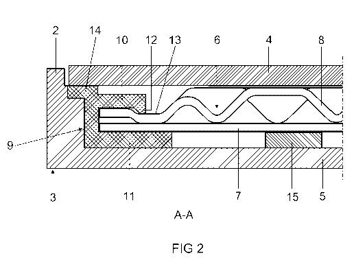
Figure 2 shows a partial sectional illustration of the
lighting system 1 shown in figure 1 along the section line
AA. The flat lamp 6 is located between the protective
shield 4 and the baseplate 5 of the trough-shaped
receptacle 3. The flat lamp 6 has a planar bottom plate 7
and a corrugated front plate B. Strip-like outer
electrodes (not illustrated), which are used for
CA 02683829 2009-10-14
PCT/EP2008/054263 - 7 -
20.08P06681WOUS
operating a dielectrically impeded gas discharge within
the flat lamp, are located on the outer side of the bottom
plate 7. For further details regarding the flat lamp known
per se, reference is made, for example, to the document
US 6 762 549 by the Applicant. The edge region of the flat
lamp 6 is provided with a frame 9, which is in the form of
an elongate U profile injection molded with silicone.
Owing to the use of silicone, a high degree of ageing
resistance and UV resistance, alongside low levels of out
gassing, is achieved. The frame 9 has two limbs 10, 11 of
different lengths which are connected in the form of a U
and which engage around the edge region of the flat lamp
6. The upper limb 10, which is the most closely adjacent
to the front plate 8, has a tab-like protrusion 12, which
engages in a matching depression 13 in the edge region of
the front plate 8. In order to plug on the frame 9, the
two slightly flexible limbs 10, 11 are bent slightly and
plugged over the thicker edge region of the flat lamp 6
until the protrusion 12 latches into the depression 13.
With the aid of the frame 9, the flat lamp 6 is fitted
into the trough-shaped receptacle 3. The frame 9 has in
each case a supporting section 14 on the upper limb 10,
which supporting section firstly rests on a shoulder of
the side wall 2 of the trough-shaped receptacle 3 and
secondly acts as a support for the protective shield 4
thereon. The supporting sections 14 arranged along the
periphery of the frame 9 ensure that the bearing force of
the protective shield 4 does not act on the flat lamp 6.
In addition to the frame 9 which encloses and holds the
flat lamp 6 at the edge region, a few thin, elastic
bearing strips 15 which are made from cellular rubber and
are adhesive on two sides (for example "double coated foam
tapes"
CA 02683829 2009-10-14
PCT/EP2008/054263 - 8 -
2008P06681WOUS
by the company 3M) and with a thickness of at least 2 mm
are also provided between the bottom plate 7 of the flat
lamp 6 and the baseplate 5 of the trough-shaped receptacle
3. Cellular rubber by the company Polyfoam has also proven
suitable for this purpose.
Figure 3 and 4 show a variant 16 of the lighting system
shown in figures 1 and 2, in a schematic plan view and,
respectively, partial sectional view along the line BB. In
addition here, a peripheral integral over-frame 17 is
plugged in clamping fashion onto the trough-like
receptacle 3. The over-frame 17 has an angular profile
with the two limbs 18, 19 which are at right angles with
respect to one another. The first limb 18 overlaps the
outer edge of the protective shield 4. The second limb 19,
which is at right angles with respect to said first limb,
surrounds the outer side of the peripheral side wall 2 of
the trough-shaped receptacle 3. By virtue of the over-
frame 17 which is plugged on in clamping fashion, the
individual components of the flat lighting system 16 are
kept together and finally the flat lamp 6 including the U
profile frame 9 is secured within the receptacle 3.