Note : Les descriptions sont présentées dans la langue officielle dans laquelle elles ont été soumises.
CA 02683833 2009-10-14
WO 2008/129286 PCT/GB2008/001395
-1-
TITLE
.Air cleaners for electrical machines
DESCRIPTION
Technical Field
The present invention relates to air-cooled electrical machines. In particular
the
invention provides an improved air cleaner apparatus for open-ventilated
electrical
machines.
Background Art
All electrical machines generate heat during their operation. This heat is
detrimental
to the operation as overheating decreases the operational efficiency of a
machine and
may even cause damage. In extreme cases, overheating of an electrical machine
can
cause complete failure. It is therefore necessary that all electric machines
are cooled.
At the simplest level, small low-power electrical motors may be cooled
sufficiently
through thermal contact with their surrounding environment. However, most
electrical machines require a much greater degree of cooling and therefore
incorporate
a suitable cooling system. There are many different cooling systems that are
currently
in use. For example, machines may be cooled by a closed circuit carrying a
liquid
coolant to a heat exchanger or by direct gas cooling. The specific cooling
system that
is incorporated with any electrical machine will depend on the size, power and
construction of the machine, among other factors.
Cooling systems inevitably add to the size, weight and cost of the electrical
machine.
Cooling can be a particular problem for electrical machines that are required
to be
particularly small, light and low cost, for example wind turbine generators.
In such
machines it is preferable to minimize the size and weight of the cooling
system.
Therefore it is often preferable that the cooling systems of such machines
utilise the
surrounding air to cool the machine. This is because such systems are not
required to
contain and circulate large quantities of heavy liquid coolant, which can add
significantly to the weight and size of the cooling system. It is even more
preferable
that surrounding air is used to directly cool such machines without the use of
bulky
CA 02683833 2009-10-14
WO 2008/129286 PCT/GB2008/001395
-2-
and heavy heat exchangers. Direct cooling of electrical machines by the
surrounding
air is often known as open-ventilation.
Open-ventilation is a very efficient cooling method for electrical machines
since there
is no intermediate heat exchange system which would otherwise reduce the
available
temperature rise for the machine. However, open-ventilation systems are not
commonly used without some form of protection because the surrounding air used
to
cool open-ventilated electrical machines often carries dirt dust, moisture;
salt and
other impurities. If the surrounding air does contain substantial quantities
of airborne
particles then significant damage can be caused to the exposed parts of the
machine
during passage of that air through the open-ventilation system. The damage is
caused
by the particles colliding with the exposed parts of the machine. This problem
is
compounded by the fact that, in order to increase the degree of cooling
provided by
open-ventilation systems, it is preferable that the cooling air is forced by
mechanical
means to pass through the electrical machine at a relatively high-velocity
and/or
pressure. This can make the damage caused by particles colliding with exposed
parts
of the machine much worse. As a result, it is usually necessary that open-
ventilation
systems incorporate a means of removing at least some of the particles from
the air
that eriters the electrical machine.
Currently, in order to prevent particles from entering open-ventilated high-
power
electrical machines, they are usually contained within box-type enclosures.
These
enclosures allow open-ventilation of the electrical machine via blow-through
inlet and'
outlet chambers. The most coinmon are National Electrical Manufacturers
Association (NEMA) 11-type enclosures. In these enclosures the incoming air is
channelled in ducting through at least three 90 changes of direction and into
a low
velocity air chamber before entering the machine. This has the result of
separating
out a proportion of the airbome particles present in the incoming air before
the air
enters the electrical machine itself.
Although box-type enclosures do remove a proportion of the particles from the
incoming air, they have been found not to be effective enough for many
situations.
CA 02683833 2009-10-14
WO 2008/129286 PCT/GB2008/001395
For example, machines with NEMA II-.type enclosures have particularly suffered
in
desert situations, where the surrounding air may contain particularly high
quantities of
solid particles, especially sand. Furthermore, mechanically increasing the
velocity of
the air passing through a box-type enclosure reduces its efficiency in
removing
particles from the air. Box-type enclosures also have a problem with the build
up of
particulate matter which has been removed from the air passing through the
enclosure.
This is because, as the enclosures clean the air in a passive manner, relying
on
changes of direction and a low velocity air chamber and have no active way of
ejecting the particles back into the surrounding air, a relatively large
proportion of the
particles that are removed from the air simply build up within the enclosure.
Over
time this leads to a decrease in the efficiency of operation of any enclosure.
It also
means periodic cleaning of box-type enclosures in order to remove particle
build-up is
necessary.
Filters are also commonly used to clean incoming air in open-ventilated
machines.
Filters are used either in isolation, as the sole method of cleaning the air,
or integrated
with other,air-cleaning devices. For example, filters are commonly
incorporated in
the box-type enclosures discussed above. Typically, filters are comprised of
simple
mesh screens that are located in positions such that all the air entering the
open-
ventilation system must pass through at least one filter. Large particles
present in the
incoming air cannot pass through the filter or filters and are thereby
prevented from
passing throughout the electrical machine.
Some electrical machines have more than one set of filters. Specifically, some
machines may have open-ventilation systems formed such that the incoming air
first
passes through a relatively coarse filter designed to remove larger particles
and then
through a progression of finer filters, each designed to remove smaller
particles than
the immediately preceding filter.
Upon initial use, filters are reasonably effective at removing large particles
from air
entering an open-ventilation system. However, their effectiveness deteriorates
with
time, especially if they are not regularly maintained. The rate of
deterioration can be
CA 02683833 2009-10-14
WO 2008/129286 PCT/GB2008/001395
-4-
particularly hard to predict as it depends upon external factors, including
the quantity
and nature of any particles present in the incoming air. Furthermore, some
filters such
as box-type enclosures, only passively remove particles from the incoming air.
That
is, a relatively large proportion of particles removed from the incoming air
by the
filters simply accumulate within the open-ventilation system. It is also very
difficult
to use filters to remove extremely small particles from incoming air,
particularly if a
high air velocity and/or pressure is utilised within an open-ventilation
system.
Due to the disadvantages described above, neither box-type enclosures nor
filters, or
even a combination of the two, provides a reliable method of removing airborne
particles in environments where the surrounding air has high particle content
or where
the air passes through an open-ventilation system at high-velocity and/or
pressure.
There is therefore a need for an improved air cleaner apparatus for removing
particles
from incoming air in open-ventilated electrical machines. Such an apparatus is
required to be small and light-weight, and preferably low in cost. It is
preferable that
any such apparatus is capable. of being incorporated with current conventional
enclosures and open-ventilation systems. It is also preferable that the
apparatus is
capable of use with high-velocity and/or high pressure open-ventilation
systems and
in environments where the air may contain large amounts of particles. It is
also
desirable that such an apparatus actively removes the particles from the open-
ventilation system in order to prevent the build up of such particles within
the system.
As a result of this need, it has previously been proposed to use centrifugal
force, as
applied by a fan or other such rotating means, to remove solid or liquid
particles from
air entering an open-ventilation system. One example of such an apparatus is
disclosed in JP 56125950. In this apparatus air is allowed to enter an open-
ventilation
system from the surrounding environment, the solid particles present in the
air are
removed and the air is then channelled into an electric machine. Specifically,
air is
allowed to enter the open-ventilation system via an inlet formed in the centre
part of
the front side of a filter frame. The incoming air then enters a conical
passage where
it is subjected to a rotary force. Solid particles present in the incoming air
are thrown
radially outwards into a dust collecting chamber surrounding the conical
passage.
CA 02683833 2009-10-14
WO 2008/129286 PCT/GB2008/001395
-5-
The cleaned air then passes through a filter and into the electric machine. In
this
manner, the open-ventilation system of JP 561 25950 provides active cleaning
of
incoming air. However, this system does not expel the particles that are
removed
from the incoming air. Instead those particles are collected within a dust
collecting
chamber. Therefore periodic emptying of the dust collection chamber is
necessary.
An electric machine incorporating a similar open-ventilation system is
disclosed in
GB 1106589. In this system cooling air is drawn into a chamber that is formed
at one
end of the casing of the electric machine. The air entering the chamber is
immediately rotated by a fan that is mounted on the drive shaft of the
electric machine
and that also acts to draw the surrounding air into the open-ventilation
system. Solid
particles present in the incoming air are thrown to the radially outer edge of
the
chamber as a result of the centrifugal force applied by the fan. These
particles then
enter an outlet air stream rather than passing through the machine. The outlet
air
stream is formed only at the radially outer edge of the chamber. Therefore,
the
majority of the incoming air is allowed to enter and circulate around the
machine. In
this manner the electrical machine of GB 1106589 provides active cleaning of
incoming air. This machine also expels solid particles cleaned from the
incoming air
completely out of the machine. This means that the expelled particles cannot
build up
within the machine and decrease the efficiency of its operation or cause it
damage.
The open-ventilation system of GB 1106589 has a number of problems. First,
because the fan that is providing the centrifugal force to the incoming air
also acts to
draw the air into the machine the two processes are inseparable. This means it
is not
possible to independently regulate the centrifugal force applied to the
incoming air
and the volume of air that is drawn into the machine, as may be desired.
Furthermore,
although the particles that are removed from the incoming air are generally
thrown
towards an outlet air stream, there is little or no active force which draws
those
particles into the outlet, air stream, other than the centrifugal force from
the drive-shaft
fan. As a result, it is likely that a relatively high proportion of the solid
particles
entering the open-ventilation system of GB 1106589 will not be removed from
the
system and will be circulated around the electric machine.
CA 02683833 2009-10-14
WO 2008/129286 PCT/GB2008/001395
-6-
Due to the problems discussed above, open-ventilation systems that utilise
centrifugal
force to remove solid particles from incoming air have not been employed for
use on
electrical machines on a commercial scale. This is despite the concept being
known
for many years. For example, the basic concept was disclosed as long ago as
1964 in
GB 977042.
Summary of Invention
The present invention provides an air cleaner for a forced air open-
ventilation system
of an electrical machine, the open-ventilation system having a high-velocity
outlet
stream, the air cleaner comprising an air chamber that may optionally include
a first
end and a second end, opposite the first. The air chamber has at least one
inlet
(typically located at the first end) through which air can be drawn in from
the
surroundings by the open-ventilation system, at least one first outlet
(typically located
at the second end) through which air can be drawn out of the air chamber by
the open-
ventilation system, rotating means contained within the air chamber and
drivable to
rotate about an axis, and wherein the air chamber further comprises at least
one
second outlet through which air can be drawn out of the air chamber by the
high-
velocity outlet stream of the open-ventilation system.
The air cleaner of the present invention operates in the following manner. Air
containing particulate matter to be removed (e.g. solid or liquid particles)
is allowed
to enter the open-ventilation system of the electrical machine from the
surrounding
environment. This air then enters the air chamber of the air cleaner at its
first end via
the at least one inlet. The air in the air chamber, and particles suspended in
the air,
may then be rotated by the rotating means such that they are subject to a
centrifugal
force that acts to throw the air radially outwardly and towards the at least
one second
outlet of the air cleaner. The centrifugal force provided by the rotating
means acts to
separate out any particles present in the air via a process of sedimentation.
. In other
words, particles that enter the air chamber through the at least one inlet
will be thrown
radially outwardly by the rotating means such that the air within the air
chamber that
is at or near the axis of the rotating means will be substantially particle-
free, whilst air
CA 02683833 2009-10-14
WO 2008/129286 PCT/GB2008/001395
-7-
that is at or near the radially outer edge of the rotating means will contain
a relatively
high density of particles.
The forced air open-ventilation system acts to draw the air out of the air
chamber via
the at least one first outlet and the at least one second outlet. The effect
of the forced
passage of air through the open-ventilation system draws air directly out of
the at least
one first outlet at the second end of the air chamber, through the open-
ventilation
system before ejecting it from the open-ventilation system via the high-
velocity outlet
stream. Furthermore, the effect of the high-velocity outlet stream passing the
at least
one second outlet of the air chamber causes the air within the air chamber
adjacent to
the at least one second outlet to be drawn out of the chamber and join the
outlet
stream, where it is ejected from the open-ventilation system without first
passing
through the open-ventilation system.
Importantly, as the at least one second outlet of the air chamber is
preferably formed
adjacent to the radially outer edge of the rotating means, any particles that
enter the
air chamber will be thrown towards the at least second outlet by the
centrifugal action
of the rotating means. Therefore, those particles will be drawn out of the air
chamber
and into the high-velocity outlet stream via the at least one second outlet
and they will
not pass through the open-ventilation system. As a result, air that is drawn
out of the
air chamber via the at least one first outlet and that passes through the open-
ventilation system will contain much lower quantities of particles than the
air that
enters the first end of the air chamber from the surrounding environment. In
this
manner, the present invention minimises the amount of damage that may be
caused to
an electrical machine by the passage of particles through its open-ventilation
system.
A particular advantage of the air cleaner of the present invention is that the
particles
that are removed are not retained in the open-ventilation system but are
actively
ejected from the cooling system via the at least one second outlet and the
high-
velocity outlet stream. The `Bernoulli effect' helps to expel particles from
the air
chamber and thereby minimises clogging of the air cleaner. As a result, there
will be
negligible build up of particles within either the air cleaner or the open-
ventilation
CA 02683833 2009-10-14
WO 2008/129286 PCT/GB2008/001395
-8-
system. This is in contrast to box-type enclosures which, when used alone,
commonly
suffer from the accumulation of solid particles.
Preferably, the air chamber of the present invention is substantially
cylindrical such
that the axis of rotation of the rotating means is coaxial with an axis of the
chamber
and a cylindrical wall of the air chamber is formed adjacent to the radially
outer edge
of the air chamber. It is also preferable that the first and second ends of
the air
chamber are formed adjacent to the axial ends of the rotating means. That is,
it is
preferable that the air chamber is formed closely around the rotating means.
However, the first and second ends of the air chamber need not be enclosed.
Substantially the whole of,the first or second end of the air chamber may form
the at
least one first inlet or the at least one first outlet to the air chamber
respectively.
Forming the air chamber closely around the rotating means is preferable as it
minimises the weight and volume of the chamber, which is an important
consideration
in many applications.
It is preferable that the at least one inlet to the air chamber is formed such
that air
enters the first end of the chamber at or near the radially outer edge of the
rotating
means. This ensures that the air is rotated sufficiently by the rotating means
and
thereby experiences a substantial centrifugal force. This is preferred as if
the
incoming air enters the air chamber at the radially outer edge of the rotating
means it
cannot simply pass through the air chamber along the axis of the rotating
means
without being subject to a significant rotational force.
It may also be preferable that there is a single conical first inlet to the
air chamber.
For example, the first inlet may be formed such that the incoming air is drawn
into a
conical inlet via a circular opening formed at an outer or upstream end of the
inlet,
then be channelled along a conical passage formed within the conical inlet and
enter
the air chamber through an annular opening formed at a downstream end of the
inlet
and the first end of the air chamber adjacent to the radially outer edge of
the rotating
means. If the first inlet is conical, it is preferable that it is rotationally
symmetric and
coaxial with the rotating means.
CA 02683833 2009-10-14
WO 2008/129286 PCT/GB2008/001395
-9-
It is generally preferable that the at least one first outlet to the air
chamber is formed
at or near the axis of the rotating means. This is preferable as it helps
ensure that any
particles introduced into the air chamber and are thrown to the radially outer
edge of
the air chamber are not drawn out of the chamber via the at least one first
outlet and
thereby pass through the open-ventilation system. For example, there may be a
single
first outlet to the air chamber that is substantially circular, formed at the
second end of
the air chamber and is coaxial with, and has a smaller radius than, the
rotating means.
It is generally preferable that the or each at least one second outlet of the
air chamber
will be formed such that it has a first or upstream end that is formed in the
wall of the
air chamber adjacent to the radially outer edge of the rotating means and a
second, or
downstream end that is formed adjacent. to the high-velocity outlet stream.
Thereby
the effect of the outlet stream passing adjacent to the second end of the or
each at least
one second outlet will create a pressure differential across the length of
each second
outlet. That is, when the open-ventilation system is operating the pressure at
the
downstream end of each second outlet will be lower than the pressure at the
upstream
end of each outlet aided by the `Bernoulli effect'. Thus air will be drawn out
of-the
air chamber, via each second outlet, and into the high-velocity outlet stream.
As
would be appreciated by a person skilled in the art, the magnitude of this
effect can be
increased by effecting a reduction in the pressure of the high-velocity outlet
stream as
it passes each second outlet. This could be achieved by, for example, forming
the
passage through which the outlet stream travels such that it reduces in cross-
section
immediately before it passes each second outlet.
It is anticipated that it will be generally preferable that the or each at
least one second
outlet is formed at the lower side of the air chamber. In this manner any
particles that
are precipitated out of the air by.the rotating means or simply by loss of
kinetic energy
will fall to the bottom of the air chamber where they will pass through the at
least one
second outlet and are ejected from the open-ventilation system by the high-
velocity
outlet stream.
CA 02683833 2009-10-14
WO 2008/129286 PCT/GB2008/001395
-10-
It may also be preferable that the hot air leaving the open-ventilation system
is used to
warm the air chamber of the air cleaner. This may prevent moisture contained
in the
air entering the air chamber from condensing within the air chamber, mixing
with any
dust or other soluble particles in the air chamber and thereby clogging the
air cleaner.
Despite the above, it is to be appreciated that the design of any air cleaner
according
to the present invention should be created according to its specific intended
use.
Design factors that may be varied include the number of first inlets and first
and
second outlets along with their size, shape and positioning. The size and
nature of the
rotating means may also be varied. The preferred design for any air cleaner
according
to the present invention will maximise the clean air leaving through the at
least one
first outlet whilst simultaneously minimising the leakage of dirty air through
that
outlet or outlets. Any design according to the present invention may be
evaluated and
adapted using computer analysis tools, as would be understood by a person
skilled in
the art.
The air cleaner of the present invention may be formed in an open-ventilation
system
either such that the surrounding air enters the at least one first inlet of
the air cleaner
directly or such that it first passes through a preliminary portion of the
open-
ventilation system. However, it is generally preferable that the length of any
preliminary portion of the open-ventilation system is minimised. This is
because the
air that passes through such a preliminary portion will not yet have been
cleaned by
the air cleaner and therefore may contain a large quantity of particles. These
particles
could cause significant damage to any such portion of the open-ventilation
system.
This is particularly important if a machine is operating in an environment
where
forced air open-ventilation would not normally be used due to the high
particle
content of the surrounding air but is made possible by the inclusion of an air
cleaner
according to the present invention, for example a desert location.
Air forcing means within open-ventilation systems are particularly susceptible
to
damage caused by collision with particles carried by the air passing through
such
systems. It is therefore preferable that if the air cleaner of the present
invention is
CA 02683833 2009-10-14
WO 2008/129286 PCT/GB2008/001395
-11-
incorporated in a forced air open-ventilation system, the air forcing means is
located
at, or near, the high-velocity outlet stream but before the at least one
second outlet of
the air chamber. Locating the air forcing means in this manner is preferable
as the air
cleaner acts to remove particles from the air passing through the open-
ventilation
system from the at least one first outlet to the air chamber and diverts the
removed
particles to the high-velocity outlet stream via the at least one second
outlet of the air
chamber. Therefore, there will be negligible, or at least greatly reduced,
quantities of
particles passing through such open-ventilation systems between these two
points and
it is preferable to locate the air forcing means therein.
It is preferable that the present invention is incorporated, in an open-
ventilation system
having an air forcing means that is a large diameter, high pressure fan.
Furthermore, in order to protect either the air forcing means or the
electrical machine
being cooled by the open-ventilation system from damage, it may be generally
preferred to provide further protecting means within the open-ventilation
system. For
example, filters may be included in the open-ventilation system and these may
act as a
back-up protection to collect any smaller particles not collected by the air
cleaner.
Such protecting means would be positioned within the open-ventilation system
to
ensure that particles are removed from the air passing through the system
before the
air passes through and cools the associated electrical machine.
In order to further protect against damage caused by particles passing through
an
open-ventilation system containing an air cleaner according to the present
invention it
may be preferable that the internal components of the associated electrical
machine
are protected. For example, the windings of the machine may be enclosed and
the
other internal components may be given a weatherproof protective treatment.
When operating the rotating means of the present invention is driven to
rotate. This
may be achieved by a number of different methods. If the electrical machine
being
cooled by the open-ventilation system is a rotating electrical machine, the
rotating
means of the air cleaner may be formed directly on the shaft of the rotating
machine,
CA 02683833 2009-10-14
WO 2008/129286 PCT/GB2008/001395
-12-
such that is driven by the rotation of the electrical machine. This
construction ensures
that the rotating means is rotated, and therefore the air cleaner is
functioning, at all
times when the associated rotating electric machine is operating. Furthermore,
this
construction may minimise the weight of the air cleaner as a separate drive
mechanism for the rotating means is not required. However, in some situations
this
construction may not be preferred as the speed of rotation of the rotating
means will
necessarily be the same as the speed of rotation of the electrical machine. It
is not
possible to independently regulate the centrifugal force applied to incoming
air by the
rotating means in open-ventilation systems formed in this manner.
Alternatively, air cleaners according to the present invention may be
constructed such
that the rotating means is indirectly driven by the rotation of shaft of the
associated
electrical machine. For example, it may be driven by a drive mechanism that is
powered by the rotation of the shaft of the electrical machine but that
enables the
rotating means to rotate at a different speed from the shaft. Such a drive
mechanism
might be such that the rotating means always operates at a fixed ratio of the
rotational
speed of the shaft of the electrical machine. As a further alternative, the
drive
mechanism might enable the rotational speed of the rotating means to be
controlled
substantially independently from the rotational speed of the shaft, for
example
through the use of a gearing mechanism.
Alternatively, air-cleaners according to the present invention may be
constructed such
that the rotating means is driven by a driving means that is substantially
separate from
the associated electrical machine. For example, the rotation of the rotating
means
may be driven and controlled by a separate independent motor.
It is preferable that the rotating means of an air cleaner according to the
present
invention is driven such that its rotational speed may be controlled
independently
from the operation of the associated electrical machine. This is because it
may be
desirable to vary the degree to which the air. entering the open-ventilation
system is
cleaned without altering the speed of operation of the electric machine. For
example,
it may be preferable that the rotating means is rotated at a higher speed when
there is
CA 02683833 2009-10-14
WO 2008/129286 PCT/GB2008/001395
13-
a larger quantity of incoming air and/or the incoming air has a relatively
high particle
content and that the rotating means is only rotated at low speeds, or possibly
not
rotated at all, when the incoming air is has a low or negligible particle
content.
If the rotating means is controlled independently. from the electric machine
the
operation of the rotating means may be controlled by a feed-back system. The
characteristics of the air entering the cooling system, such as the speed aind
particle
content of the air, may be determined by sehsing means, for example one or
more
sensors. The sensing means would control the rotating means to operate at a
speed
suitable for . the air conditions via feed-back to control unit. Sensors may
be
positioned in the air surrounding the open-ventilation system or within the
air cleaner
or open-ventilation system. They may directly measure the characteristics of
the air
entering the system or may determine them indirectly, for example from the
characteristics of the air leaving the system, or the power output of the
electrical
machine itself.
Similarly, as will be appreciated by a person skilled in the art, the air
forcing means of
an air cleaner according to the present invention may also be driven directly
or
indirectly by the associated electrical machine or may be driven independently
from
that machine.
Preferably, the rotating means of the air cleaner and the air forcing means of
the
associated open-ventilation system may be controlled independently. The speed
of
rotation of the rotating means is generally proportional to the degree of
cleaning
provided to air entering the open-ventilation system. The air forcing means
controls
the rate of passage of air through the open-ventilation system and therefore
the degree
of cooling provided by the open-ventilation system. As a result, it is often
beneficial
to control the two independently of each other. For example, in relatively
clean
environments when the associated electrical machine is operating at or near
its
maximum rate it may be necessary to circulate air through the open-ventilation
system
at a high rate in order to provide a satisfactory degree of cooling but it may
not be
necessary to operate the air cleaner due to the clean surrounding environment.
CA 02683833 2009-10-14
WO 2008/129286 PCT/GB2008/001395
-14-
Conversely, in environments where the surrounding air contains high quantities
of
particles, it may be necessary to operate the air cleaner even when only a
relatively
low degree of cooling is required from the open-ventilation system.
However, it is to be understood that, whilst it is preferable that the
rotating means of
the air cleaner and the air forcing means of the open-ventilation system are
controlled
separately, satisfactory open-ventilation systems containing air cleaners
according to
the present invention may also be constructed such that the control of the
rotating
means and the air forcing means are intimately related. For example,
satisfactory
open-ventilation systems containing air cleaners according to the present
invention
having both the rotating means of the air cleaner and the air forcing means of
the
open-ventilation system mounted on the shaft of an associated rotating
electrical
machine may be constructed.
The present invention may be formed as an independent component that can be
affixed to and removed from a separate forced air open-ventilation system.
Alternatively, the present invention may be formed as an integral part of a
forced air
open-ventilation system.
The present iinvention is particularly suitable for incorporation in open-
ventilation
systems that are used to cool wind turbine generators
The operation of the present invention can be simply mathematically modelled.
Very
approximately, when a particle enters the first end of the air chamber via the
first inlet
it will be travelling parallel to the axis of the rotating means. In order for
that particle
to be expelled through the at least one second outlet of the -air chamber and
not pass
straight through the chamber it must be deflected radially outwards by the
rotating
means. That is, the centrifugal force exerted on the particle by the rotating
means
must deflect the particle radially outwards from the central axis and out
through the at
least one second outlet. However, air velocity pressure acting radially
inwards within
the air chamber, will directly oppose the centrifugal force. Therefore, if a
particle is
CA 02683833 2009-10-14
WO 2008/129286 PCT/GB2008/001395
- 15-
to be removed from the air cleaner via the at least one second outlet the
centrifugal
force from the rotating means must exceed the aerodynamic radial inward force.
The centrifugal force (in Newtons) acting upon a particle can be approximated
as:
F, =MwZR
where M= the mass of the particle (kg);
R = the distance of the particle from the central axis of the rotating means
(m);
- and
w= rate of rotation of the rotating means (rad/sec).
The velocity pressure of a fluid (in Pa) can be approximated to be:
P= 0.5 p v2
where p = density of fluid (kg/m3); and
v = radial velocity of fluid (m/sec).
Therefore the particle will experience an inward force (in Newtons) due to the
velocity pressure of:
F2=PA
where A the aerodynamic surface area of the particle (m2).
Typically, an exemplary air cooled rotating machine may operate at 1500 rpm,
have a
power rating of 5 MW and an efficiency of 97.8%. If this machine is air cooled
a
temperature rise in the air passing through the machine of 45 K would be
considered
acceptable and, therefore the machine would require a cooling air flow rate of
approximately 2.4 m3/sec. Such a machine may use an air cleaner according to
the
CA 02683833 2009-10-14
WO 2008/129286 PCT/GB2008/001395
-16-
present invention with a I m diameter air chamber containing a rotating means
of
substantially the same diameter.
If a particle enters the air cleaner of the above machine at_the radially
outer edge of
the air chamber it will experience a centrifugal force of:
Fl - 2 6Q00 20.5M= 12300 M
C ~
A spherical particle within the air chamber will have a mass of:
M= 43 r3po
where r = the radius of the particle in metres; and
po = the density of the particle (kg/m3).
Therefore:
F1 = 12300 3 r3po
Fj=51700r3po
The mean radial velocity of the air in the air chamber is dependent upon the
air flow
rate through the air chamber and the air entry area of the at least one first
outlet.
Specifically, the mean radial velocity can be approximate to be:
v= f
a
where f= the mean flow rate of air through the air chamber (m3/sec); and
CA 02683833 2009-10-14
WO 2008/129286 PCT/GB2008/001395
-17-
a = the mean air entry area of the at least one first outlet (m2).
Preferably, the air entry area of the at least one first outlet will be
maximised in order
to produce a radially inward air velocity within the air chamber. For example,
in the
above machine with an air chamber radius of 1 m the air entry area of the at
least one
first outlet may be 0.8 m2 (i.e. a= 0.8). The density of air is very
approximately 1.2
kg/m3, therefore within the air cleaner of the above machine:
F2 =~ 1.2 O;g 1z A= (5.4) A
CJ
If a particle is spherical its aerodynamic area is equal to:
A=7E r2
and:
F2 = 5.4 (7t rz) = 17.0 rZ
A particle will be deflected radially outwards by the rotating means if:
F, > F2
51700 r3 po > 17.0 r2
rpo>3.3x10⁴
Thus, whether a particle entering the air chamber is deflected by the rotating
means is
dependent upon its size and density. Using the calculations above it can be
shown
that a particle of sand (density 2500 kg/m3) passing through this specific air
cleaner
would have to be less than 0.26 gm in diameter not to be deflected by the
rotating
means. Similarly a water particle (density 1000 kg/m3) would have to be
smaller than
0.66 gm in diameter not to be deflected by the rotating means.
CA 02683833 2009-10-14
WO 2008/129286 PCT/GB2008/001395
-18-
However, it is to be understood that the calculation given above is highly
simplified
and based upon a large number of assumptions. A person skilled in the art will
appreciate that a detailed computational fluid dynamic study is required to
optimise
the design of any air cleaner according to the present invention.
Draw~
Figure 1 is a schematic cross-section of a forced air open-ventilation system
that
includes an air cleaner according to the present invention and is integrally
formed
about an electrical machine;
Figure 2 is a detailed cross-sectional view of an electrical machine that
incorporates a
forced air open-ventilation system that includes a preferred embodiment of an
air
cleaner according to the present invention; and
Figure 3 is a close-up cross-section of a part of the open-ventilation system
of Figure
2 that shows the air cleaner.
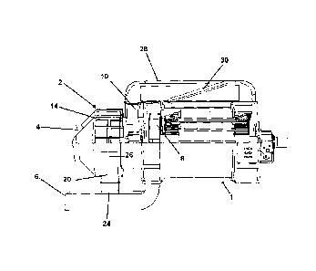
The operation of an air cleaner 2 according to the present invention may be
understood with reference to Figure 1. The open-ventilation system of which
the air
cleaner 2 forms a part is a one-way system. That is, air enters the system
from the
surrounding environment via a conical inlet 16, passes through the system and
exits
via a single outlet 6. The air is forced through the open-ventilation system
by a large-
diameter high-pressure fan 8 that is located near the outlet 6 and is
channelled through
the system in ducting 10. The direction of passage of the air through the open-
ventilation system is indicated in Figure 1 by arrows.
The air cleaner 2 is substantially comprised of a cylindrical air chamber 12
that
contains an air rotating means 14. The air chamber 12 has a conical inlet 16,
a first
outlet 18 and a second outlet 20. The rotating means 14 is driven to rotate
about a
central axis 22. A downstream end of the inlet 16 is situated at a first end
of the air
chamber, the first outlet 18 is situated at a second end of the chamber and
the central
axis extends between the first and second ends of the chamber and is
substantially
coaxial with the inlet 16 and the first outlet 18. The second outlet 20 is
formed in a
wall of the chamber 22 between the first inlet 16 and the first outlet 18,
radially
CA 02683833 2009-10-14
WO 2008/129286 PCT/GB2008/001395
-19-
outwards from the central axis 22 and adjacent to the radially outer edge of
the
rotating means 14. The first outlet 18 leads, via a section of ducting 10 to a
filter
enclosure 28 that'is formed on an upper side of an electrical machine 1. The
second
outlet 20 leads to a portion of the open-ventilation system that is located
after the fain
8 but before the outlet 6.
When the open-ventilation system is operating, the fan 8 acts to draw
surrounding air
into the system through the conical inlet 16 and it is thereby channelled into
the air
chamber 12. As the inlet 16 . is conical, air enters the air chamber 12 at or
near the
radially outer edge of the rotating means 14 and the air chamber.
During operation of the open-ventilation system the rotating means 14 of the
air
cleaner 2 is driven to rotate. The rotation of the rotating means 14 results
in a
centrifugal force being applied to air entering the air chamber 12. In
particular, this
applies a centrifugal force to any solid or liquid particles or other impurity
particles
present in the air that is channelled into the air chamber 12 and acts to
throw those
particles radially outwardly from the central axis 22 of the rotating means
14. In this
manner it is ensured that particles entering the air chamber 12 remain near
the radially
oliter edge of the air chamber, adjacent to the second outlet 20 and away from
the first
outlet 18. Air is drawn out of the air chamber 12 by the action of the fan 8
through both the first
outlet 18 and the second outlet 20. The action of the fan 8 directly draws air
out of
the chamber 12 through the first outlet 18. Due to the location of the first
outlet 18 at
or near the central axis 22 of the rotating means 14, air that is drawn out of
the air
chamber 12 through that outlet will be substantially particle free. In this
manner the
air that passes through the electrical machine 1 will be significantly cleaner
than the
air that enters the open-ventilation system from the surroundings.
Air drawn out of the first outlet 18 is channelled through the open-
ventilation system
by the ducting 10. After the cleaned air has been drawn out of the air chamber
12
through the first outlet 18 it is channelled through ducting 10 to a filter
enclosure 28
CA 02683833 2009-10-14
WO 2008/129286 PCT/GB2008/001395
- 20 -
formed on the upper side of the electrical machine 1. The filter enclosure 28
contains
a large filter 30 that removes from the air any particles that have not been
removed by
the air cleaner 2. Furthermore, the filter 30 may act as a back-up to protect
the
electrical machine 1 should the air cleaner 2 fail. The filter 30 is
positioned at an
acute angle to the direction of flow of the air in order to maximise its
effective surface
area. The filter enclosure 28 is externally accessible so that the filter 30
can be easily
monitored and replaced if necessary. Monitoring the particle build up on and
around
the filter 30 may give an indication as to the function of the air cleaner 2.
For
example, if a large quantity of particles are being filtered out of the air
the air cleaner
2 may not be functioning adequately.
After passing through the filter enclosure 28 the air is channelled through
the
electrical machine I where it acts to cool the machine in a conventional
manner, as
would be understood by a person skilled in the art. As a further back-up
against
failure of the cleaner 2 the windings of the electrical machine 1 are sealed
and the
other internal components of the machine are given a weatherproof protective
treatment. After passing through and cooling the electrical machine I the air
passes
through the large-diameter high-pressure fan 8 and is ejected from the open-
ventilation system in the high-velocity outlet stream.
The large-diameter high-pressure fan 8 also indirectly acts to draw air out of
the air
cleaner 2 through the second outlet 20. Specifically, the fan 8 creates the
high-
velocity outlet stream and the action of that stream passing a downstream end
24 of
the second outlet 20 creates a pressure differential across the length of the
second
outlet 20 due to the `Bernouilli effect'. The pressure at the downstream end
24 will
be reduced by this effect and therefore will be lower than the pressure at an
upstream
end 26 that is formed in the air chamber 12. The pressure difference results
in air
being drawn out of the air chamber 12 through the second outlet 20 and into
the high-
velocity outlet stream. As the first end 26 of the second outlet 20 is formed
in the air
chamber 12 adjacent to the radially outer edge of the rotating means 14,
particles that
enter the air chamber 12 in the incoming air and are thrown to the radially
outer edge
of the rotating means 14 will be drawn. out of the air chamber through the
second
CA 02683833 2009-10-14
WO 2008/129286 PCT/GB2008/001395
-21-
outlet 20 so that they can be ejected by the high-velocity outlet stream of
the open-
ventilation system and will not pass through the electrical machine 1.
A preferred embodiment of the present invention can be, seen in Figures 2 and
3. The
construction of this embodiment is substantially as described above and as
schematically illustrated in Figure 1. Therefore, the same reference numerals
have
been used to denote the features of the preferred embodiment. However, further
specific features of the preferred embodiment will be understood from the
following
description.
In the preferred embodiment a wind turbine generator 1 is cooled by an open-
ventilation system containing an air cleaner 2 according to the present
invention. The
wind turbine generator 1 is of a conventional construction.
Both the rotating means 14 of the air cleaner 2 and large-diameter high
pressure fan 8
of the open-ventilatiori system are mounted on the shaft 32 of the generator
1. This
ensures that the open-ventilation system, including the air cleaner 2, is
operating when
the generator 1 is running and the generator will always be cooled
sufficiently. This
construction also ensures that the rotating means 14 and the fan 8 always
rotate at the
same rate as-the shaft of the generator 1.
The conical inlet 16 and the air chamber 12 of the preferred embodiment are
formed
such that air entering the chamber inlet must pass through the rotating means
14.
Specifically, the air chamber 12 has an intermediate wall 34 that is
concentric with the
outer wall 36 of the chamber. The intennediate wall 34 extends approximately
half-
way across the chamber from the first end of the chamber that is adjacent to
the
conical inlet 16. The radius of the intermediate wall 34 about the central
axis 22 is
substantially equal to the radius of the inlet 16 at its intersection with the
air chamber
12 and the intermediate wall and the inlet are joined thereat. In this manner,
air
entering the air chamber 12 must pass through an annular channel formed
between the
intermediate wall 34 and the outer wall of the chamber.
CA 02683833 2009-10-14
WO 2008/129286 PCT/GB2008/001395
-22-
The rotating means 14 is formed along the axial length of the air chamber 12
and
consists of a plurality of vanes 38 that are rotatable about the central axis
of the air
chamber. Each vane 38 extends axially along the length of the air chamber 12
and is
contained within the annular channel formed between the intermediate wa1134
and the
outer wall 36 of the air chamber over approximately half of their axial
length. Thus,
when the generator I is operating, air drawn into the air chamber 12 will
necessarily
be subject to the action of the rotating means 14.
The second outlet 20 is formed at the lower side of the air chamber 12 such
that any
particles that are precipitated out of the air by the rotating means 14, or
simply by loss
of kinetic energy, and that fall to the bottom of the chamber 12 will pass
through the
second outlet 20 to the chamber and are ejected from the open-ventilation
system.
The area of the first outlet 18 of the air chamber 12 is maximised in order to
minimise
the velocity of the air within the air chamber in the radially inward
direction.
Specifically, the first outlet 18 is a circular opening formed at the second
end of the
air chamber 12 and is coaxial with the air chamber. The radially outer edge of
the
first outlet 18 is formed a small distance radially inwardly from the inner
edges of the
vanes 38 of the rotating means 14 in order to minimise the number of particles
that
exit the air chamber 12 through the first outlet. Minimising the velocity of
the air in
the radially inward direction minimises the velocity pressure of the air
within the air
chamber 12. As discussed above, and as will be apparent to a person skilled in
the art,
this is important as the velocity pressure of the air opposes the centrifugal
force from
the rotating means 14.
After air has passed through the first outlet 18 it will pass through ducting
10 to the
filter enclosure 28. Any remaining particles in the air will be removed by the
filter
before the air passes through and cools the generator 1. The air will then
pass through
the fan 8 before exiting the open-ventilation system at the outlet 6.