Note : Les descriptions sont présentées dans la langue officielle dans laquelle elles ont été soumises.
CA 02684524 2009-11-05
229021
METHOD FOR MOUNTING COMPONENTS AT A WIND TURBINE
BACKGROUND
The present disclosure generally relates to the
construction of a wind turbine, and in particular relates
to a method and a device for mounting components at wind
turbine support units of a wind turbine. Methods for
mounting components at a wind turbine are manifold, such
as drilling holes and thread cutting. The mounting
components may be used to support units of the wind
turbine, e.g. cables, cable tubes, etc.
SUMMARY
In view of the above a method for mounting components at
a wind turbine support unit of a wind turbine is
provided, the method including the steps of providing a
captive bolt gun, providing a fastening means, inserting
a captive bolt into the fastening means, and shooting the
captive bolt into the wind turbine support unit by means
of the captive bolt gun such that the fastening means is
fixed at the wind turbine support unit.
According to another aspect a use of a captive bolt for
mounting components in a wind turbine is provided.
According to yet another aspect a wind turbine including
at least one wind turbine support unit is provided,
wherein at least one fastening means adapted for mounting
components at the wind turbine support unit of the wind
turbine is fixed at the wind turbine support unit by
means of at least one captive bolt.
1
CA 02684524 2009-11-05
229021
Further exemplary embodiments are according to the
dependent claims, the description and the accompanying
drawings.
DRAWINGS
A full and enabling disclosure, including the best mode
thereof, to one of ordinary skill in the art is set forth
more particularly in the remainder of the specification
including reference to the accompanying drawings wherein:
Fig. 1 shows a construction of a captive bolt having a
threaded bolt portion according to a typical embodiment;
Fig. 2 illustrates a captive bolt without threaded bolt
portion according to another typical embodiment;
Fig. 3 illustrates yet another captive bolt having a
bushing according to yet another typical embodiment;
Fig. 4 is an explosive view of the components which are
fixed by a captive bolt at a wind turbine support unit;
Fig. 5 shows the components shown in Fig. 4 wherein the
captive bolt has been inserted into a fastening means
which may be fastened at the wind turbine support unit
shown in Fig. 4;
Fig. 6 shows the components shown in Fig. 4 and 5 wherein
the captive bolt 101 has been inserted into the wind
turbine support unit such that the fastening means is
fastened; and
Fig. 7 is a flowchart illustrating a method for mounting
components at a wind turbine support unit of a wind
turbine according to a typical embodiment.
2
CA 02684524 2009-11-05
229021
DETAILED DESCRIPTION
Reference will now be made in detail to the various
exemplary embodiments, one or more examples of which are
illustrated in the drawings. Each example is provided by
way of explanation and is not meant as a limitation. For
example, features illustrated or described as part of one
embodiment can be used on or in conjunction with other
embodiments to yield yet a further embodiment. It is
intended that the present disclosure includes such
modifications and variations.
A number of embodiments will be explained below. In this
case, identical structural features are identified by
identical reference symbols in the drawings. The
structures shown in the drawings are not depicted true to
scale but rather serve only for the better understanding
of the embodiments.
Fig. 1 illustrates a captive bolt 101 according to a
typical embodiment. The captive bolt 101 includes a tip
portion 107 which may be driven into a support unit (not
shown in Fig. 1). The material of the captive bolt 101
may be steel having high chromium and/or nickel content.
The captive bolt 101 may be driven into materials such as
aluminium, concrete or steel. A washer 106 may be
arranged around the axis of the captive bolt 101 in order
to fix a fastening means (not shown in Fig. 1) and in
order to prevent that the captive bolt is shot through
the fastening means. Furthermore, the captive bolt 101
includes a head portion 109 used to fix the fastening
means. The captive bolt 101 shown in Fig. 1 moreover
includes a threaded bolt portion 105 which can be used to
3
CA 02684524 2009-11-05
229021
screw the bolt further into the material of a support
unit.
It is noted here that a captive bolt gun may be provided
in order to drive the captive bolt 101 into the support
unit. The use of a captive bolt gun for mounting
components of a wind turbine at wind turbine support
units saves mounting time and thus costs during the
installation of a wind turbine. Components which are
mounted at support units of a wind turbine include
cables, cable tubes, etc.
These components require many fastening means which have
to be mounted at the support units. By just shooting the
captive bolts 101 onto the support unit using a captive
bolt gun, a large amount of the mounting time for
mounting the fastening means at the support unit is
saved.
Fig. 2 exhibits a captive bolt according to another
typical embodiment. The captive bolt 101 shown in Fig. 2
includes a tip portion 107 and a head portion 109.
Furthermore, a washer 106 is provided in order to be able
to fix fastening means without punching the captive bolt
101 through the fastening means. The captive bolt 101
shown in Fig. 2 has no threaded bolt portion as the
captive bolt 101 shown in Fig. 1.
Thus it is possible to fix a fastening means at a support
unit without screwing the captive bolt 101. The captive
bolt 101 is just driven into the material of the support
unit by shooting it using the captive bolt gun.
Fig. 3 illustrates a captive bolt 101 which has no tip
portion 107 as the captive bolts 101 shown in Fig. 1 and
4
CA 02684524 2009-11-05
229021
2. The captive bolt 101 shown in Fig. 3 has a flattened
front end which may be inserted into a hole in a support
unit which has been drilled in advance.
When the captive bolt 101 is driven into the support unit
by means of a captive bolt gun, a portion of increased
diameter of the captive bolt 101 shown in Fig. 3 provides
a fixing of the captive bolt 101 in the drilled hole. The
captive bolt 101 shown in Fig. 3 moreover includes a
bushing 108 which is used to provide an efficient fixing
of a fastening means at a support unit.
Fig. 4 is an explosive view of components used for
fastening a fastening means 102 at a wind turbine support
unit 100. It is noted here that the wind turbine support
unit 100 may be any part of the wind turbine where
components such as cables, cable tubes, etc. are mounted.
As shown in Fig. 4, the fastening means 102 is provided
with a cable connector 103 where cables and cable tubes
may be fastened. Using a captive bolt gun (not shown in
Fig. 4), the captive bolt 101 is driven in a shooting
direction 201 along an insertion axis 110 towards the
wind turbine support unit 100. Without drilling the hole
into the wind turbine support unit 100, it is possible to
fix the fastening means 102 firmly at the wind turbine
support unit 100.
Fig. 5 shows the situation at a step following the
mounting step shown in Fig. 4. As shown in Fig. 5, the
captive bolt 101 has been inserted into a mounting hole
104 of the fastening means 102 or directly into the
fastening means 102 in the insertion direction 201.
CA 02684524 2009-11-05
229021
With the captive bolt 101 thus inserted into the mounting
hole 104 of the fastening means 102 or directly into the
fastening means 102, it is possible to shoot the captive
bolt 101 - fastening means 102 - assembly onto the wind
turbine support unit 100. The captive bolt gun is held
atop the head of the captive bolt 101 and shoots the
captive bolt 101 together with the fastening means 102
towards the wind turbine support unit 100.
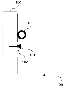
Fig. 6 shows the situation after the captive bolt 101 has
been shot into the wind turbine support unit 100 in the
insertion direction 201. The fastening means 102
including the cable connector 103 is firmly fixed at the
wind turbine support unit 100 by means of the captive
bolt 101.
It is noted here that the captive bolt having the
threaded bolt portion 105 as shown in Fig. 1 may be used
instead of the captive bolt shown in Figs. 4-6 without
threaded bolt portion. In this case it is possible, in
addition to shooting the captive bolt 101 into the wind
turbine support unit 100, to fasten the captive bolt 101
by screwing it into the wind turbine support unit 100.
Furthermore, a washer 106 (shown in Fig. 2) may be used
in the mounting situations shown in Figs. 4-6.
Fig. 7 is a flowchart illustrating a method for mounting
components at a wind turbine support unit 100 of a wind
turbine according to a typical embodiment.
The procedure starts at a step Sl. At a step S2, a
captive bolt gun is provided which is adapted for
shooting captive bolts 101 (shown in Figs. 1-6) into the
wind turbine support unit 100 (shown in Figs. 4-6). Then
6
CA 02684524 2009-11-05
229021
the procedure advances to step S3. At step S3, a
fastening means 102 (shown in Figs. 4-6) which may have a
mounting hole 104 is provided.
At a step S4, a captive bolt 101 (shown in Figs. 1-6) is
inserted into the mounting hole 104 of the fastening
means 102 or directly into the fastening means 102. Then
the procedure advances to a step S5 where the captive
bolt gun is used for shooting the captive bolt 101 in a
direction shown by an arrow 201 in Figs. 4-6.
After having shot the captive bolt 101 into the wind
turbine support unit 100 by means of the captive bolt
gun, the fastening means 102 is firmly fixed at the wind
turbine support unit 100. At step S6, the procedure is
ended.
The invention has been described on the basis of
embodiments which are shown in the appended drawings and
from which further advantages and modifications emerge.
However, the disclosure is not restricted to the
embodiments described in concrete terms, but rather can
be modified and varied in a suitable manner. It lies
within the scope to combine individual features and
combinations of features of one embodiment with features
and combinations of features of another embodiment in a
suitable manner in order to arrive at further
embodiments.
It will be apparent to those skilled in the art, based
upon the teachings herein, that changes and modifications
may be made without departing from the disclosure and its
broader aspects. That is, all examples set forth herein
above are intended to be exemplary and non-limiting.
7