Note : Les descriptions sont présentées dans la langue officielle dans laquelle elles ont été soumises.
CA 02684531 2009-10-16
WO 2008/129231 PCT/GB2008/001081
1
SEAT WITH DYNAMIC SEAT BACK
The present invention relates to seats, in particular
an improved seat back arrangement for a seat. More
specifically the present invention relates to a seat for
those with a disability.
It is generally desirable to make a seat as comfortable
as_possible, while providing adequate support and ensuring
a good postural position, to a user. This is particularly so
in seats for those with a disability who may spend prolonged
periods in such a seat.
In addition disabled users may require a seat that
provides specific support, and in addition they may place
further demands, in particular in terms of robustness of the
seat, on the design of a seat. Such specialist disabled
seats and seating systems may be for use as a wheelchair, by
attachment to a suitable wheeled base, or may be for
freestanding fixed use with or without height adjustment.
Seats may incorporate an adjustable seat back which
can, in particular, be pivoted about its lower attachment to
the seat bottom reclined to various reclined positions to
support and suit a user. In most conventional seats the seat
back is fixed in the various adjusted reclined positions and
the seat back provides a rigid supporting surface. Indeed a
number of seats specifically seek to provide such a rigid
supporting surface to support a user. However such rigid
seat backs can be uncomfortable.
In addition to withstand the forces which may be
applied by a user the seat must be relatively robust
resulting in a relatively massive and heavy structure to
withstand the loads on the seat back.
Examples of various disabled seating arrangements which
incorporate seat backs which although adjustable are fixed
in use are described in US 5,228,747 and US 5, 4470-6. s
mentioned such seat backs can be uncomfortable due to _,Uheir
CA 02684531 2009-10-16
WO 2008/129231 PCT/GB2008/001081
2
inflexibility.
Seats with moveable seat backs which can flex to
accommodate and absorb movement and loading by a user, so
called dynamic seats, are also known. These seats
incorporate springs, typically gas springs, to resist
movement of the seat back and absorb the loading and
rearward movement of the seat back. Once loading is removed,
and for example when a user leans forward, the seat back
springs back into an upright position. Such seats are
however less common especially in specialist seats for those
with disabilities, and in general are relatively crude.
Examples of various movable seat back arrangements are
described in US 2005/018450; US 5,501,507; US 3,059,971 and
US 5,704,689. These however all relate to office or task
chairs rather than the more specific disabled seating
arrangements, and are not tailored nor adapted to meet the
specific and exacting demands of disabled seats. Indeed
there are problems with such arrangements that can be
improved.
Overall, and in particular in the context of disabled
seating, it has been found that there are problems with both
the conventional adjustable seat back arrangements and the
conventional dynamic seat backs, and that both arrangements
can be improved.
In particular in some conventional adjustable seat back
arrangements and conventional dynamic seat backs the entire
seat back pad provides a single rigid support surface and/or
moves as single unit. In use when a user leans back against
the seat back loading is primarily via the shoulder region
and upper part of the back. Resulting forces are then
transferred through the lower body and seat back and the
pelvis, and legs, are forced forward on the seat. This may
leave the lower back unsupported and the user in an
asymmetric position. With conventional dynamic backs the
CA 02684531 2009-10-16
WO 2008/129231 PCT/GB2008/001081
3
position of the pelvis may similarly be moved as the seat
back moves.
Alternatively with some of the dynamic seat back
arrangements the rearward movement of the seat back allows
the pelvis to move rearward. Once the seat back then returns
to the upright position, since the position of the pelvis
region has been altered, the seat back may undesirably force
the user forwards and/or otherwise alter the position of the
user on the seat. These problems are particularly
experienced by those who have particular muscular control
problems, and extensor problems, for example those
associated with cerebral palsy, where the user may arch
their back and provide uneven loading on the seat back. As
a result the seat does not provide the best support nor
ensure good posture of the user within the seat.
In addition, it has also been found, especially with
the relatively crude spring return movement provided by
conventional dynamic seat back arrangements, that some
disabled users may respond by continually moving and
bouncing against the seat back. This is generally
undesirable, and also means that the seat and seat back has
to be reinforced to withstand such repeated impact loading.
It is therefore desirable to provide an improved seat
arrangement which addresses the above identified problems
and/or which more generally offers improvements or an
alternative over existing arrangements
According to the present invention there is therefore
provided a seat as described in the accompanying claims.
In a first embodiment of the invention there is
provided seat back assembly for a seat comprising a first
seat back portion defining a first back support surface for
supporting a first portion of a user's back, and an second
CA 02684531 2009-10-16
WO 2008/129231 PCT/GB2008/001081
4
seat back portion defining a second back support surface for
supporting a second portion of a user's back, wherein the
second portion is moveable independently to the first
portion.
The seat back assembly provides, in particular disabled
users, with improved support in an upright position in which
where the pelvis is better maintained at set angle to ensure
a good postural position.
In addition the seat back assembly accommodates upper
body movement or absorb forces from extensor patterns
commonly associated, for example with cerebral palsy.
Beneficially, the first seat back portion is a lower
seat back portion defining a lower back support surface for
supporting a lower portion of a user's back, and the second
seat back portion is an upper seat back portion for
supporting an upper portion of a user's back. The lower seat
back portion is preferably arranged and configured to
support the pelvis and pe-l-vic region of a user sitting on
the seat.
In one exemplary embodiment, the assembly may comprise
a base frame, wherein the first and second seat back
portions are mounted from the base frame. The lower seat
back portion is beneficially adjustable in terms of one or
more of its height, its angle relative to the seat, its
longitudinal position relative to the seat. Accordingly, the
lower seat back portion is preferably pivotally mounted
relative to the above-mentioned base frame.
The upper seat back portion is preferably reclineably
moveable relative to the seat. Accordingly, the upper seat
back portion may be reclineable to a selected one of a
number of fixed angular positions. Alternatively or in
addition, the upper seat back portion may be reclineably
mounted for movement under a load over a range of angular
positions, possibly from a fixed position. In the case where
the upper seat back portion is mounted for dynamic reclining
CA 02684531 2009-10-16
WO 2008/129231 PCT/GB2008/001081
mcvement (under a load over a range of angular positions),
the upper seat back portion is preferably biased to a
forward upright position. The forward biasing force is
beneficially adjustable. Furthermore, a damper is preferably
5 provided to resist (i.e. slow) movement of upper seat back
portion. In this case, the damping force provided by the
damper is preferably also adjustable. The biasing and
damping forces are beneficially provided in an shock
absorber for controlling movement of the upper seat back
portion.
The upper and/or lower seat back portions are
preferably provided with respective cushioned pads for the
comfort of the user.
In a second embodiment of the invention there is
provided a seat back assembly for a seat comprising a seat
back portion defining a back support surface for supporting
a user's back, said seat back portion being moveable under
an applied load over a range of positions, and a damper for
restraining motion of said seat back portion.
In a specific exemplary embodiment of the present
invention, there is provided a seat back assembly for a seat
comprising a seat for supporting a user's weight and a seat
back portion defining a support surface for supporting a
user's back, wherein said seat back portion is moveable
relative to said seat, under an applied load over a range of
positions, and wherein shock absorbing means are provided
for applying a tension and/or rebound force in respect of
movement of said seat back portion, said shock absorbing
means having means for adjusting the tension and/or rebound
force applied thereby.
In one exemplary embodiment, the seat back portion is
provided with an arm member, telescopically mounted in a
housing containing damping means, wherein movement of said
seat back portion causes corresponding movement of said arm
member within said housing.
CA 02684531 2009-10-16
WO 2008/129231 PCT/GB2008/001081
6
The present invention extends to a seat comprising a
seat base frame, a seat for supporting a user and a seat
back assembly as defined above mounted on the seat base
frame and extending at an angle to the seat.
These and other aspects of the present invention will
be apparent from, and elucidated with reference to, the
embodiments described herein.
The present invention will now be described by way of
example only with. reference to the following figures in
which:
Figure 1 is a perspective illustration of a seat
arrangement in accordance with an embodiment of the
invention;
Figure 2 is a more detailed side view of the seat back
assembly mounting of the seat shown in Figure 1;
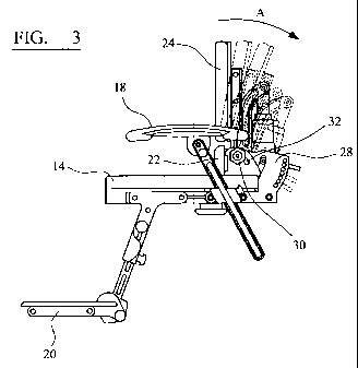
Figure 3 is a side view of the seat shown in Figure 1
showing the seat back assembly in various adjusted reclined
positions;
Figure 4 is a side view of the seat shown in Figure 1
showing the dynamic movement of the seat back assembly from
one of the adjusted reclined positions;
Figures 5A to 5C are respective side views of the seat
shown in Figure 1 separately showing the seat back assembly
in various adjusted reclined positions indicated in Figure
3; and
Figures 6A to 6C are respective side views of the seat
shown in Figure 1 separately showing the dynamic movement of
the seat back assembly indicated in Figure 4.
A seating system 10 for a disabled user, an in
accordance with an embodiment of the present invention, is
shown in Figure 1. While the invention is particularly
directed to a specialist seating systems 10 for a disabled
CA 02684531 2009-10-16
WO 2008/129231 PCT/GB2008/001081
7
users it may also be more generally applicable.
The seating system 10 may be attached and supported on
a suitable base structure (not shown) as is known in the
art, for use as a wheelchair, by attachment to a suitable
wheeled base, or may be for freestanding use with or without
height adjustment, as is known in the art.
Preferably the seating system 10 is a modular seating
system for use with various base structures. To this end the
seating system 10 includes a mounting spigot 1 to engage a
seat base structure. It will however be appreciated that the
seating system 10 may incorporate an integral base structure
and/or supporting legs.
The seating system 10 includes a base frame 12 upon
which is mounted a seat bottom cushion 14 which defines a
generally horizontal seat bottom support surface for
supporting a user and upon which a user sits. A seat back
assembly, which will be described further below, is also
mounted on the seat base frame 12 via a seat back mounting
bracket 28 (Figure 2).
The seat back assembly extends at an angle to the seat
bottom cushion, and is generally upright to support the back
of a user sitting on the seat. While the seat bottom
cushion is generally horizontal and the seat back is
generally upright and vertical, it will be recognized that
these terms are only relative and indicative of the
orientation of the seat bottom cushion and seat back
assembly, and that strict compliance is not required. Both
the seat bottom cushion and seat back assembly being at an
angle to the strict horizontal and vertical planes.
As shown the seating system 10 also includes arm and
foot rests 18, 20, the positions and attachments of which
are adjustable to suit a user. Such adjustable arm and foot
rests 18, 20 are conventional and will not be described
further. In addition while such adjustable arm and foot
rests 18, 20 are desirable in particular for use in seating
CA 02684531 2009-10-16
WO 2008/129231 PCT/GB2008/001081
8
systems for disabled users, they may be replaced with
different even fixed arrangements, or even omitted in
certain other embodiments and in particular in more general
seating systems not specifically configured from disabled
users.
In more detail, the seat back assembly 16 comprises a
lower seat back portion 22 and a separate distinct upper
seat back portion 24 disposed adjacent and generally above
the lower seat back. portion 22. The first lower seat back
portion 22 includes a lower support pad defining a first
back support surface for supporting a lower portion of a
user's back, and in particular a sacral pad for supporting
the pelvis and pelvic region of a user seated on the seat.
The second upper seat back portion 24 includes an upper
seat pad defining a second upper back support surface for
supporting an upper portion of a user's back, and
specifically the shoulder region of a users back. The first
and second portions 22, 24 while separate and distinct
collectively define a support surface for supporting all of
a user's back.
Referring additionally to Figure 2 of the drawings, the
lower seat back portion 22 further comprises a lower seat
back support bracket 26 attached to the rear of the lower
seat back pad. The lower seat back support bracket 26
adjustably attaches the lower seat back portion 22 to a
seat back mounting bracket 28 attached to the seat base
frame 12 via a mounting bolt (not shown) secured to the seat
back mounting bracket 28 with an adjustment knob 30 threaded
on a treaded end of the bolt. The bolt is located in an
arcuate guide slot 32 in the lower seat back support bracket
26 and the adjustment knob 30 is tightened to clamp the
lower seat back support bracket 26 between the adjustment
knob 30 and seat back mounting bracket 28 at a position
along the arcuate guide slot 32.
In this way the lower seat back portion 22 is
CA 02684531 2009-10-16
WO 2008/129231 PCT/GB2008/001081
9
adjustably mounted to the seat back mounting bracket 28 and
the seat 14, so that it can be independently pivoted and
tilted about the mounting bolt, and also forward and
backwards and upwards and downwards along the guide slot 32
and relative to the seat back mounting bracket 28 and
remainder of the seat, and then clamped in any of the
adjusted positions by tightening the adjustment knob 30. In
this way, the sacral pad on the lower seat back portion 22
is made adjustable, which allows the dynamic back action to
control the angle of the pelvis and accommodate a range of
different height users. ,
The upper seat back portion 24 comprises an upper pad
mounted upon an upper seat back support frame 34 which is
pivotally attached, via a pivot pin (not shown) at a lower
end, to the seat back mounting bracket 28. The support frame
34 also includes a first fixed support arm 36 fixed to the
support frame 34. The first arm 36 may, in other
embodiments, comprise an integral part of the support frame
and the present invention is not intended to be limited in
this regard.
A second, movable, support arm 38 is pivotally attached
at one end about the same pivot axis and pin as the support
frame 34 so as to be pivotable relative to the support frame
34. A distal end of the moveable arm 38 includes a mounting
pin 40 which is located in, and moveable along, a guide slot
(not shown) in the seat back mounting bracket 28, and is
engageable in any one of a number of corresponding reclined
position apertures 42 defined in an arc in the seat back
mounting bracket 28 to secure the moveable arm 38 in a
number of angular positions about its pivotal mounting and
the pivotal mounting of the seat back frame 34.
Thus, as shown in Figures 3 and 5A-5C, the seat back
assembly can be adjusted to, and fixed in, any one of a
number of set nominal 'home' reclined positions. A shock
absorber 44 is pivotally mounted between a distal end of the
CA 02684531 2009-10-16
WO 2008/129231 PCT/GB2008/001081
fixed arm 36 and the moveable arm 38. The shock absorber
fixes the position of the fixed arm 36, and so of the upper
seat back 24 relative to the moveable arm 38 by virtue of
the length of the shock absorber
5 Referring to Figures 3 and 5A-5C, in use, a user sits
on the seat bottom cushion 14 with their feet resting on the
foot rests 20 and their arms resting on the arm rests 18.
The lower portion of the user's back, i.e. the pelvis and
pelvic region, is supported by the lower seat back portion
10 22 and the upper portion of the user's back is supported by
the upper seat back portion 24. The lower seat back portion
22 is adjustable relative to the seat back mounting bracket
28 by manually pivoting or tilting it about the mounting
bolt and/or forward/backward, upward/downward movement along
the guide slot 32 and it can then be clamped in the desired
adjusted position relative to the seat back mounting bracket
28 and the seat 14 by tightening the adjustment knob 32.
Adjustment of the upper seat back portion 24 relative
to the rest of the seat assembly 10 is effected by applying
a load in the direction indicated by arrow A in Figure 3 to
the upper seat back portion 24, when the mounting pin 40 is
not engaged with any of the apertures 42. In response to
this load, the upper seat back portion 24 pivots about its
pivotal mounting and the mounting pin slides along its guide
slot until the desired reclined position is reached. The
upper seat back portion 24 can be fixed in the desired
reclining position by engagement of the mounting pin 40 in
one of the apertures 42.
Thus, it will be apparent that, by the above-described
mechanism, the upper seat back portion 24 is reclineably
adjustable to one of a number of fixed angular positions.
In order to return the upper seat back portion 24 to the
upright position (or adjust it to another reclining
position), the mounting pin 40 can be disengaged from the
respective aperture 42 and the upper seat back portion 24
CA 02684531 2009-10-16
WO 2008/129231 PCT/GB2008/001081
11
re-adjusted, as described above.
Referring to Figures 4 and 6A-6C of the drawings,
dynamic movement of the upper seat back portion 24, form the
fixed nominal home positions is also possible. This is
effected via the shock absorber 44 located between the
distal end of the moveable arm 38 and the fixed arm 36. A.
shock absorber 44 suitable for use in the present invention
may comprise a cylindrical housing within which the moveable
arm is telescopically mounted for movement. Damping means,
in the form of a fluid chamber or biasing spring, is
provided within the housing, in communication with the
moveable arm 38. As the moveable arm 38 extends into the
housing due to movement of the upper back support portion 24
caused by a load applied thereto, the fluid in the chamber
or the biasing spring is compressed, thereby applying a
tension force against the movement and slowing movement of
the upper back support portion 24. Equally, when the load is
reduced or removed, a return force is applied to the
moveable arm 38 which causes the upper back support portion
24 to return toward the upright forward position.
The tension and/or rebound forces produced by the
damping means are preferably adjustable. In the case of a
fluid chamber, the size of the fluid chamber may be
adjustable for this purpose. In the case of a biasing
spring, the preload thereof may be adjustable. Other types
of shock absorber in which the tension and rebound are
adjustable will be apparent to a person skilled in the art.
For example, it is known to provide a shock absorber in a
front suspension fork of a mountain bike and such a shock
absorber tends to be adjustable for tension and rebound to
compensate for, for example, various rider weights,
abilities, type of terrain, etc. One example of a
particularly suitable adjustable shock absorber which may be
used is the BAR Rock Shox produced by SRAM Corporation of
Illinois, USA. While this is geenraly used for mountian
CA 02684531 2009-10-16
WO 2008/129231 PCT/GB2008/001081
12
bikes it can be advantageously used in this seat
application.
Thus, returning to Figures 4 and 6A-6C of the drawings,
in use, load applied to the upper seat back portion 24 by
the user causes the fixed arm 36 to pivot about the pivot
axis and the moveable arm 38 extends further into the
hoizsing of the shock absorber 44, resisted by the damping
force produced by the damping means therein. As the load
being applied increases, the upper seat back portion 24 is
further reclined until it reaches a maximum reclining
position (Figure 6C). The reclining angle can be reduced
simply by reducing the load being applied. When the force is
removed, the upper seat back portion 24 is returned to the
upright position by the rebound force provided by the shock
absorber 44 (see Figure 4). The shock absorber 44 and
damping force provided also resists this return movement
slowing the return movement to the set nominal position.
This is particularly advantageous for disabled seating and
also reduces any impact with a user who may now be sitting
more upright. In addition it reduces impact with the
remainder of the seat as the seat back portion 24 returns to
the nominal set position.
Thus, it will be appreciated that the dynamic action
does not affect the back recline mechanism, this can still
be set independently. Further benefits include the fact that
the back frame and sacral pad work independently which
allows the angle of the pelvis to be maintained as the back
frame is flexed; the sacral pad is adjustable, which allows
the dynamic back action to accommodate a range of different
heigh users; and the shock absorber is adjustable in tension
and rebound.
The adjustable shock absorber mechanism 44 has been
used in mountain bikes but has never been incorporated into
a seating system or wheelchair. It will also be appreciated
that a key difference between this adjustable shock absorber
CA 02684531 2009-10-16
WO 2008/129231 PCT/GB2008/001081
13
mechanism 44 and a traditional gas spring is it is design
for cyclic loading. The barrel is larger to assist with heat
dispersion and has an air chamber so that the tension can be
manually adjusted. Advantages over the conventional gas
spring arrangement include less feedback to the user, more
comfort, reduced loading and reduction in weight of the
seat. In contrast to the above-described embodiment of the
invention, conventional dynamic seat back arrangements do
not include damping (adjustable or otherwise) for slowing
the movement of the seat back (in either direction).
As stated above, the dynamic action (described with
reference to Figures 4 and 6A-6C) does not affect the back
recline mechanism (described with reference to Figures 3 and
5A-5C), this can still be set independently.
The overall combination of separate sacral pad and main
back rest with relative adjustment and the damping
functionality of the shock absorber give overall combined
improvement, as well as providing their own respective
individual improvements.
More specifically, the adjustable shock absorber could
be used as a damper in a seat assembly having a conventional
single back rest portion incorporating the upper and lower
seat back portions. Equally, the arrangement comprising two
separate, independently adjustable, seat back portions could
be used with no damping. Furthermore, while shown as
separate pads, the upper and lower seat back pads could be
integrated into a single back rest with separate moveable
frames and/or both portions could be covered by a single
cover layer.
The principle and mode of operation of this invention
have been explained and illustrated in its preferred
embodiment. However, it must be understood that this
invention may be practiced otherwise than as specifically
explained and illustrated without departing from its spirit
or scope.