Note : Les descriptions sont présentées dans la langue officielle dans laquelle elles ont été soumises.
CA 02684584 2009-10-19
WO 2008/129397 PCT/1B2008/000946
1
STERILIZATION SYSTEM FOR PET CONTAINERS AND BOTTLES
Field of the invention
The present invention relates to the sterilization of item surfaces and gases
and
specifically to the sterilization obtained mainly by means of the interaction
of
electrons with item surfaces and environments and with gas or air contained or
flowing therein and to synergistic effects thereof.
State of the art
In the fields of medicine, pharmaceutical production and food processing, the
need for sterilization is critical for the protection against the risk
deriving from
detrimental microorganisms. Most of the sterilization methods used nowadays
require that the sterilizing agent systematically penetrates the item to be
sterilized.
These methods include the sterilization by means of heat, where the item to be
sterilized is subjected to heating and pressure, for instance in an autoclave.
Heat
and pressure penetrate within the item to be sterilized and kill the
detrimental
microorganisms after a sufficient time. Gases such as hydrogen peroxide or
ethylene oxide are also used to sterilize items. The gas needs to permeate the
entire item for a complete sterilization. An alternative sterilization method
employs
ionizing radiations, such as gamma rays, X rays or high energy electrons.
There are however many target items in which the exposure to sterilizing
agents
would cause deleterious effects for the item itself. Examples include items
which
would melt or would deteriorate upon exposure to heat, products which would
deteriorate or react with the sterilizing chemical agents, and materials which
would
detrimentally be altered upon exposure to high energy radiation, especially
ionizing radiations. It has been recognised in the past that the deleterious
effect
does not occur if the ionizing radiation remains confined to the surface of
the
target item. However, most of the ionizing radiations are generated by
powerful
beam generators, such as accelerators, so that the resulting radiation beam is
by
its own nature penetrating.
US Patent No. 4801427 discloses a process for the dry sterilization of medical
equipment subjected to an electric discharge in a gaseous atmosphere, which
produces an active plasma. In an embodiment, Jacob discloses how items are
placed on a conveyor belt which leads them to a gap where an atmospheric-
pressure discharge is generated by corona discharge in ambient air. The plasma
CA 02684584 2009-10-19
WO 2008/129397 PCT/1B2008/000946
2
is formed by discharge between the conveyor belt, which is grounded and acts
as
a cathode, and a plurality of needle-shaped nozzles, which act as anodes,
which
disperse a ionizing gas; such a gas may be an oxidizing gas such as oxygen, or
a
reducing gas, such as hydrogen.
U.S. Patent No. 5,200,158 discloses the sterilization by exposure of an item
to a
gas plasma generated by an electric discharge in a gaseous atmosphere under
reduced pressure. Hydrogen, oxygen, nitrogen and inert gases are all
recommended as possible gases for the formation of the plasma.
As opposed to the high energy approach of this patent, US Patent No. 3780308
to
S. Nablo discloses the sterilization of item surfaces by using low-energy
electrons,
although there is a particularly high energy starting point. One of the
advantages
of low-energy electrons is that, as they do not penetrate in the volume of the
item,
they do not modify the mechanical properties of the material to be sterilized.
Nablo has broadened his idea with US Patent No. 4652763, which discloses the
use of an electron beam having an energy sufficient to penetrate the outer
layer
but not such as to pass through the inner layer of the target material.
Several patents disclose the use of a gas plasma to obtain the surface
sterilization. In US Patent No. 3948601, Fraser et al. disclose the use of a
continuous flow gas plasma, introduced at a very low pressure in a chamber
containing the target item to be sterlized. A cold plasma is continuously
produced
by a gas such as argon, by means of the exposure to a radiofrequency field.
One
of the problems encountered in the previously devised devices is connected to
three-dimensional structures, such as vials, cuvettes and sleeves. Sometimes
these structures have profiles which generate shadow areas for a ionizing
radiation beam and not even a diffused discharge such as electrons or reactive
ions reaches such areas which will result poorly sterilized. A solution would
be to
rotate or direct the item to be sterilized at a different angle.
Another possibility claimed in U.S. Patent No. 6623706B2 consists in using two
electron generators positioned one in front of the other with respect to the
item to
be treated, so as to each cover the shadow areas left by the other.
Recently there have been many publications and patents related to
sterilization
methods, such as US Patent No. 6682696 B1, 2004, related to the use of
hydrogen peroxide, US Patent No. 2004/022673 which provides for the use of
CA 02684584 2014-08-25
3
peracetic acid, formalin, etc, U.S. Patent No. 6945013, which employs hydrogen
peroxide and ozone. U.S. Patent No. 2006/0032189 as well as U.S. Patent No.
2007/0065335 and U.S. Patent No. 6,432,279, 2002, provide for ozone and water-
dissolved ozone.
Therefore, the main technical problem to be solved is to achieve the
sterilization of
elaborate-shaped containers without subjecting them to deteriorating
temperatures for the container itself, such as PET containers.
Summary of the invention
It is the object of the present invention to provide a sterilization, sealing
and
marking system for PET containers and bottles adapted to solve the above said
problems. The solution is carried out by means of a sterilization system for
PET
containers and bottles.
According to another aspect of the invention, said problems are solved by
means
of a sterilization method.
Brief description of the drawings
Further features and advantages of the invention will become more apparent in
light of the detailed description of a preferred though not exclusive
embodiment of
a sterilization, sealing and marking system for PET containers and bottles,
shown
by way of non-limitative examples, with the aid of the accompanying drawings
in
which:
Figure 1 shows a cable-and-trunk schematic of sterilization for containers by
means of radiations;
Figure 2 shows a configuration similar to the previous figure, in which the
containers to be sterilized are arranged at a different radiation exposure
angle;
Figure 3 shows a cable-and-trunk schematic in which the containers to be
sterilized move along a circumference and are exposed to the radiations one at
a
time;
Figure 4 shows, with respect to the previous figure, a different configuration
of the
irradiation of the containers;
Figure 5 shows a section view of a sterilization system highlighting the
wheeled
handling system and the electronic flow generator;
CA 02684584 2009-10-19
WO 2008/129397 PCT/1B2008/000946
4
Figure 6 shows a portion of a vertical section corresponding to the previous
figure,
highlighting the irradiation area of the containers and of corresponding
capsules,
the generator and the corresponding electron accelerator;
Figure 7 shows a three-dimensional view of the system with open screening
parts
which allow a partial view of the handling system for the containers near the
loading area;
Figure 8 shows another three-dimensional view of the system, by which view the
position of the sterilization wheel, of the inlet wheel and of the output
wheel for the
containers may be deduced, all three forming the handling system;
Figure 9 shows a plan view of a clamp to grip a bottle to be sterilized;
Figure 10 shows a cavalier drawing view of the clamp of the previous figure;
Figure 11 shows an elaborate rotating and washing system for a container with
a
washing nozzle introduced in the container to be blown;
Figure 12 shows the system before its activation.
Similar reference numbers and letters in the figures identify similar elements
or
components.
Detailed description of preferred embodiments of the invention
The innovative, flexible and totally computerized system includes one or more
generators 1 of electrons with a low-voltage, approximately on the order of
200-
400 KeVs and magnetic field generators or deflectors 3 and programmable post-
acceleration sections for the electron beam, which allow to make the best of
the
peculiarities of an electron beam both in the field of sterilization and in
the field of
polymerization, both for the sealing of the surface of the bottles and for
their
marking and also for their aseptic filling.
The present invention makes the best of the synergies of all of the
specifications
and various peculiarities of electron beams in the new moulding, sterilization
and
filling systems for PET containers: sterilization, ozone production, plasma,
polymerization, heating and production of X rays, etc. aided by the
introduction of
the new heating method based on Atmospheric Plasma Spray (APS) technology,
providing:
1. optimization of the dose uniformity;
2. use of PC-programmable sources of electrons on the order of 200-400
KeVs,
including at least one scanning horn or gun 2 and with a window 21 with the
beam
CA 02684584 2009-10-19
WO 2008/129397 PCT/1B2008/000946
entering at a 900 angle;
3. use of PC-programmable magnetic fields 31 for the deflection of
scattered
electrons;
4. use of PC-programmable electronic post-acceleration fields incident on
sectors for the generation of X rays;
5. flexible and PC-programmable raster or orientation of the beam scan;
6. sterilization of equipment, environment and containers with 03 generated
by
the electron beam and by UV;
7. polymerization of sealing paint with an electronic beam;
8. polymerization of date stamp, mark, etc. by an electron beam;
9. heating with APS technology.
Therefore, the object of the present invention is an integrated, flexible and
computerized system for the sterilization in general and for PET preforms,
bottles
and containers for food in particular, which employs the ionizing radiation
without
negatively affecting the PET substrate. One of the main objects is in fact to
obtain
an aseptic container by effect both of the direct radiation and by all of the
other
devices which will be disclosed, thus optimizing the uniformity of the dose
released in the container. This integrated and flexible system is more
efficient and
cost-effective than previously devised sterilization devices, as it combines
the
direct effect of the low-energy electrons of the beam with the synergistic
effect of
X rays, ozone and plasma generated by the electron beam itself, and uses the
introduction of the heating processes and APS technology.
The invention achieves the object of an effective sterilization without
needing to
resort to high energies with expensive and voluminous equipment and without
requiring an excessively high and expensive power, equipment which is moreover
subject to especially restrictive and elaborate health and licensing
standards, but
instead simply employing the synergy of the electron beam with the effects
associated thereto: plasma, ozone, X rays, sterilization and polymerization.
Such a synergy is obtained by appropriate and specific devices such as:
1) the use of a compact outlet window 21 for the electrons for the use of
appropriate magnetic fields 31, although the window extends, for example, in a
vertical direction, to allow the direct and simultaneous irradiation of at
least two
bottles even having a different shape and size, thus allowing to achieve at
least
CA 02684584 2009-10-19
WO 2008/129397 PCT/1B2008/000946
6
two transits under the beam for each single bottle, arranged according to the
most
appropriate orientation so as to have the best dose uniformity (Figures 1 and
2):
2) a better dose uniformity is also achieved in virtue of the use, figures
3 and 4,
of appropriately positioned PC-programmable magnetic fields 31, which direct
the
scattering of electrons outputted from the thin titanium window 21, with an
opening
preferably on the order of 0,15-0,05 rn, towards the shadow areas of the
bottle,
neck and bottom;
3) further advantages for the dose uniformity are achieved, as well as for
the
appropriate angle, see figures 1 and 2, of the bottle with respect to the beam
11,
by the rotation given to the bottle, for instance around its own symmetry
axis, and
made more effective by two transits under the beam;
4) another crucial contribution to the dose uniformity comes from the PC-
programming of the scan raster, thus achieving the appropriate dose in the
appropriate places;
5) a further contribution to the sterilization process is brought by the
arrangement in appropriate spots of targets or reflectors 4 made of a heavy
metal,
such as W, Ta, Hf, etc. polarized so as to convey and make the sterilizing
effect of
the scattered electrons more effective by the simultaneous production of X
rays;
6) finally, the introduction of a drop of liquid oxygen within the bottle
gives rise
to a more effective production of ozone, under the impact of electrons, with a
strong contribution to the sterilization of the inner surface of the
container.
To further optimize the synergies offered by the use of electric guns, the
system
further provides:
7) a position along the path of the bottles, where these are covered with a
microporosity sealing paint, a paint which may be polymerized by electrons and
which will therefore be polymerized when it passes under the beam;
8) similarly, along the path of the bottles, a position is provided, in
which
specific marks, date, etc. are applied with inks which polymerize by electron
beams.
The invention also provides a further extension of the synergies offered by
the use
of electronic beams to also obtain the sterilization of the entire production
and/or
treatment system of preforms and/or bottles, thus handling and appropriately
directing during this preliminary step the generator of electrons towards the
CA 02684584 2009-10-19
WO 2008/129397 PCT/1B2008/000946
7
various sectors of the system, so as to obtain the desired sterilization
through the
adjustment of the energy of the beam, the use of adjustable magnetic fields,
of
appropriately arranged and polarized heavy metal targets and of liquid oxygen
drops.
This e-beam technology for the sterilization is aided in this flexible system
by the
introduction of the new heating technology based on the provision of ohmic
resistive elements directly on the element to be heated, by the use of APS
technology.
This new APS technique is used on this innovative system anytime it is
economically convenient for the heating of equipment and components both to
sterilize, and to fluidize plastic materials for the production of preforms
for bottles
etc. The diagram of how this technique is performed is shown in figures 1 to
4.
According to figure 1, the generator 1 of the electron beam 11 irradiates
through
the horn 2 a pair of bottles or containers to be sterilized 10. The electron
beam 11
is appropriately directed by means of magnetic fields 31 generated by the
magnetic field generators 3 so as to be focused on all of the areas of the
bottle
while the latter is caused to rotate around its own symmetry axis. Also shown
are
said polarized targets 4, which are adapted to deviate said electron flow 11
towards the areas of the bottle which are more critical for the process of
sterilization.
With respect to Figure 1, Figure 2 suggests a different angle for the bottles
10 with
respect to the direction of the electron flow 11.
Figure 3 shows an example in which the bottles 10 are directed at different
angles
with respect to the previous figures in relation to the irradiated electron
flow 11. At
least one bottle 10 is directly irradiated by the electron beam, possibly
directed by
said magnetic field generators 3, while other bottles are hit by the radiation
upon
its reflection by said targets or reflectors 4, which may also be
appropriately
polarized.
Figure 4 shows a different configuration of the magnetic field generators 3
while,
with respect to Figure 3, two bottles 10 are hit by the direct radiation and
other two
are hit by the reflected radiation.
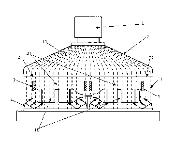
According to a preferred embodiment of a sterilization system, shown in
Figures 5
to 12, it includes a sterilization wheel 102 to which the bottles 10 are
attached
CA 02684584 2009-10-19
WO 2008/129397 PCT/1B2008/000946
8
along its circumference by appropriate clamps 200 and carried in front of the
mouth of the gun 2 which irradiates an electron flow.
Said sterilization wheel 102 is preferably coupled to an inlet wheel 101 and
to an
outlet wheel 103.
The entire path covered around said wheels is enclosed within a screening
shell.
Such a choice results from the need to screen the environment surrounding the
system from the emissions of the generator 1, which are potentially harmful
for
human health.
Near the inlet indicated by "IN" and the outlet from the system indicated by
"OUT"
of the bottles 10, there are respectively worm screws 106 and 107, which serve
the purpose of at first spacing and then drawing the bottles near, so that
they are
correctly spaced when the clamps 200 need to grip them by the neck and handle
them in the path within the system.
Said worm screws 106 and 107 rotate synchronously to the handling system
including said wheels 101, 102 and 103.
The configuration and the dimensional ratio between said wheels may be
designed so as to maximize the labyrinth effect suitable for screening the
system
from outside.
The IN loading area and the OUT unloading area are the interface towards the
external environment and must therefore form a barrier against the
introduction of
potentially polluted air within the sterilization system, accordingly an
overpressure
is generated therein with a complete filtration of the incoming air so as to
maintain
a class 100.
The transport of bottles to the IN inlet of the sterilization system, but also
externally thereto, is preferably obtained by means of said synchronous worm
screws or by a conveyor belt, in order to limit the introduction of
potentially
polluted air in the system.
The sterilization is carried out by means of the irradiation of an electronic
beam
produced by a generator 1 integrated by an accelerator machine.
The area near the irradiation horn 2 of the bottles is also maintained
overpressurized with a laminar flow of air filtered by absolute filters,
preferably
class 100 filters, although with a lower overpressure than the IN loading area
and
OUT unloading area. The reason is the need to achieve an evacuation of the
CA 02684584 2009-10-19
WO 2008/129397 PCT/1B2008/000946
9
ozone produced by the electronic beam which has a strongly ionizing power,
thus
avoiding it from escaping in the environment surrounding the sterilization
system.
A handling of the containers to be sterilized, which allows the certain
rotation of
the same in front of the beam for at least two complete rotations, is
preferably
obtained.
As will be more apparent later, said handling is achieved so as not to screen
any
area of the container from the radiation, as the non perfect irradiation of
all of the
spots on the surface of the container to be sterilized would compromise the
result
of the sterilization. The width of the beam determines the irradiation time
and the
latter must in any case be appropriate for the safety of the mechanical
handling
system. Considering that for a safe and complete rotation the rotation speed
may
not be higher than 10 rounds/sec, i.e. 600 rounds/min, the exposure time
results
being about 0,1 seconds for a complete irradiation. The width of the beam is
therefore proportional to the production throughput and to the pitch in the
handling
star. In the preferred embodiment, for a 112,5 mm spacing between the bottles,
the width of the beam at bottle level needs to be at least two times said
spacing,
thus resulting 250 mm. The length of the beam is instead equivalent to the
maximum length of the container plus an amount for the compensation of the
edge effect.
For example, for a 350 mm long container, the length of the horn will be at
least
400 mm.
The accelerator is positioned in a chamber adjacent to the irradiation area so
as to
limit the volume of the controlled environment. The gun installation chamber
is in
any case conditioned and over-pressurized and has features similar to the IN
loading area.
A proportioned cooling system is provided preventing the incident power on the
carrier system from bringing the areas in contact with the plastic of the
container
to a temperature above 60 C. The screening in the irradiation area also needs
to
be conditioned through the use of channelling in which a refrigerant fluid is
run, for
instance low temperature water.
The screening system 104 serves to reduce the emitted radiation, i.e. X rays,
from
the system to an acceptable range for the workers operating near the system.
Indeed, the dangerousness is not related to the radiation of the electron beam
CA 02684584 2009-10-19
WO 2008/129397 PCT/1B2008/000946
generated by the generator 1, which is a beta radiation that is absorbed in a
few
tenths of a mm by a substance having a density equivalent to water, but
instead to
the transformation by collision with high molecular weight metals of the
energy of
the X ray beam. Materials, which strongly absorb X rays and have labyrinth
geometries for open systems, such as the system object of the present
invention,
were therefore required.
As the use of lead as an absorbing material is a widespread practice for
limiting
the thickness of the wall, although this material should be avoided in a
machine
that processes containers for food products, as an alternative to lead, the
screening shell 104 was then preferredly made of steel with a thickness
proportionally greater than that which would have been required with lead,
because of the lower density of steel which exerts a less effective screening
effect
for the X rays. The screening depends on the energy, on the photon flow
generated by effect of the collision of electrons with the atoms of the
screening
material, on the materials used for the screening, on the amount of flow of
radiation acceptable for the worker operating on the machine. In the case of a
1
MeV energy the thickness of the lead wall may be estimated to be equivalent to
350 mm; in the case of open systems such as the case of the system for
bottles,
the radiation must be reflected at least three times before reaching the
outlet, as
each reflection cuts 99% of the energy of the radiation.
This explains the special geometry of the sterilization system which includes
said
handling system, for instance by means of stars, including said wheels 101,
102
and 103 cooperating so as to lead the handling path to be similar to a in a
plan
view.
The gripping device securing a bottle to said wheels during the handling of
the
bottle is a clamp 200 positioned on said stars.
The reflectors 4, such as the reflector 204 positioned above said gripping
device
(see Figure 10) are positioned in the irradiation chamber and have a high
atomic
weight in order to promote the generation of X rays, thus contributing by at
least
1% to the total production and, as mentioned above, contribute to the
sterilization
of the container.
The window 21 of the scan horn 2 includes at least one titanium sheet, which
tends to heat during operation, therefore its cooling and the cooling of the
CA 02684584 2009-10-19
WO 2008/129397 PCT/1B2008/000946
11
generator 1 and of the scan horn 21 in general occurs by means of one or more
jets of blown air, which is continuously recovered from the irradiation
chamber and
cooled by a heat exchanger or taken from outside and appropriately filtered.
In an advantageous variant of the invention, the sterilization of the capsules
and
caps 20 also takes place in the irradiation chamber. Placing them behind the
containers targeted by the radiation, the residual electron radiation passing
through the containers and that between adjacent containers are exploited by
means of a controlled motion by a second appropriate belt or star spacing and
handling system. Said second handling system carries the sterilized capsules
from
the irradiation chamber to the capping machine.
As an alternative, the handling of the capsules may provide a transit in an
area
adjacent to the heavy metal reflectors 4, to benefit from the X rays resulting
indirect with respect to the direct electron radiation. When the capsules are
exposed to direct and particularly intense and penetrating X rays, even the
most
elaborate capsules, such as the so-called "sport caps", may be sterilized.
The dose to be preferably achieved is always higher or equivalent to 10 kGy
and,
considering the transformation factor from electron flow to X ray flow of
about 1%,
the preferred exposure time for the capsule is about 100 times that of the
container, i.e. 10 seconds.
In a preferred embodiment of said sterilization system, as the duration of the
exposure corresponds to the axis of the emission horn, then the second
handling
system includes a feed screw within the screening wall with a determined path
in
order to ensure the above said preferred time of exposure. The capsules
sterilized
in this manner are then carried to a use station, for instance to the capping
machine within the aseptic block.
The advantage of the irradiation by X rays instead of a direct electron beam
also
resides in the fact that often the capsules are made in polypropylene (PP) and
this
material is easily deteriorated if subjected to excess dosage of electron
beam,
whereas with X rays the radiation is considerably less powerful and more
easily
managed.
Sterile air or nitrogen, or another gas is considered to be required in the
container
during sterilization of the container itself in order to achieve two purposes:
1) the
washing of the container from the presence of internal foreign bodies, before
CA 02684584 2009-10-19
WO 2008/129397 PCT/1B2008/000946
12
irradiating;
2) the washing of the container from the presence of ozone which is formed by
the
action of ionizing radiations during the process of sterilization.
Specifically, when an inert gas is introduced, the oxidation by ozone,
generated by
the electron flow, of the product which is later introduced in the container
and is
generally but not exclusively food, is avoided.
A washing air or gas inlet nozzle adapted to be introduced automatically in
the
container along the sterilization path and to nearly come into contact with
the
bottom is provided in order to achieve a good washing effectiveness.
As noted above, since it is most important to avoid screening areas for the
radiations on the container, a special clamp 200 has been provided.
Said clamp includes two elongated elements 201 and 202 which opposedly
cooperate to grip the neck of a bottle. The grip is adjusted by the load of a
spring
203 which tends to draw said opposed elements nearer. In the embodiment of
Figures 9 and 10, each of these rotates about its own fulcrum, respectively
211
and 212. Furthermore, said elements which are elongated at one end, include
gripping means 210 for the bottle neck, while at the other end they include
control
means 221 and 222 for opening the clamp 200.
Specifically, said gripping means 210 include a plurality of rollers
distributed on
both of the elongated elements to be adapted to the bottle neck to be gripped,
leaving front and rear portions free, so that no area of the bottle is
screened from
radiations.
Said control means 221 and 222 for opening the clamp include as many rollers,
which, driven by a cam or in any case by a surface they encounter during the
motion of the clamp around the handling wheels, determine the opening or
closing
of the clamp.
The number of rollers is defined so as to ensure the grip of the bottle
letting it
freely rotate about its own rotation axis.
Advantageously, said clamp allows the irradiation of the entire bottle without
determining any screening area for the sterilizing radiations.
At the opening of the bottle and at its top, a profiled plate 204 is integral
with the
clamp, the plate serving the dual function of reflecting the electron beam
otherwise lost on the bottle neck, and of converting the energy of the
electron
CA 02684584 2009-10-19
WO 2008/129397 PCT/1B2008/000946
13
beam to X rays.
Said rollers 210 are adapted to hold the neck of a bottle letting it rotate
about its
own rotation axis.
As the rotation is required only during the irradiation of the bottle, said
washing
nozzle 310 is included in an elaborate system 300 which has the dual function
of
introducing the nozzle in the bottle and rotating the bottle.
For this purpose, said elaborate system 300 is placed in the irradiation area
of the
bottle.
Said elaborate system 300 includes a rotating internally hollow rod 301,
including
at the end 3011 a coupling compatible with the mouth of the bottle, which by
being
lowered to come into contact with the mouth induces the bottle to rotate.
The washing nozzle 310 is lowered through the cavity of the rotating rod 301,
so
that while the bottle rotates and is irradiated, it is also subjected to
washing by
blowing.
The rotating rod 301 is induced to rotate by means of a threading obtained
along
the outer surface cooperating with the support 302 of the rod, thus giving
rise to a
worm screw system.
At the end or during the washing, in order to achieve sterilization, said
washing
nozzle 310 preferredly injects in the container gaseous oxygen or a drop of
liquid
oxygen in an amount proportional to the size of the container, so that the
electronic radiation converts it to ozone, which is highly disinfecting for
the inner
walls of the container.
In relation to the power of the installed generator 1, the following table
shows the
preferred dimensions of the screening shell 104 optimized for the power of the
generator used with PET containers.
Specifically, the various areas are shown in the figures through different
screens,
in relation to the lower or greater degree of screening that is to be
guaranteed. An
A-type wall with a square screen is therefore defined in immediate proximity
to the
scan gun 2, a B-type screening wall with an hexagonal screen in the
intermediate
area and, finally, a C-type part with a 450 angled hatch near the loading and
unloading area, i.e. where the radiation to be screened contains a lower
energy
content. The maximum and minimum cm thicknesses of each kind of wall are
therefore defined in relation to the installed power in keVs of the generator
1, as
CA 02684584 2009-10-19
WO 2008/129397
PCT/1B2008/000946
14
shown in the following table.
ENERGY WALL "A" WALL "B" WALL "C"
(keV) square hatch hexagonal 45
angle
(l max= 40 hatch hatch
mA) Min Max Min Max Min Max
(cm) (cm) (cm) (cm) (cm) (cm)
800 25 35 15 25 10 15
600 22 31 14 22 9 14
400 19 26 12 19 8 12
200 13 18 8 13 6 8