Note : Les descriptions sont présentées dans la langue officielle dans laquelle elles ont été soumises.
CA 02687066 2009-11-09
WO 2008/141045 PCT/US2008/062910
SINGLE JOINT ELEVATOR WITH GRIPPING JAWS
FIELD OF THE INVENTION
[0001] The present invention is directed to an apparatus and a method for
securely gripping
and releasing a tubular segment or stand of tubular segments for use in
drilling operations,
particularly for hoisting the tubular segment into alignment with a tubular
string.
BACKGROUND OF THE RELATED ART
[0002] Wells are drilled into the earth's crust using a drilling rig.
Tubular strings are
lengthened by threadably coupling add-on tubular segments to the proximal end
of the tubular
string. The tubular string is generally suspended within the borehole using a
rig floor-mounted
spider as each new tubular segment or stand is coupled to the proximal end of
the tubular string
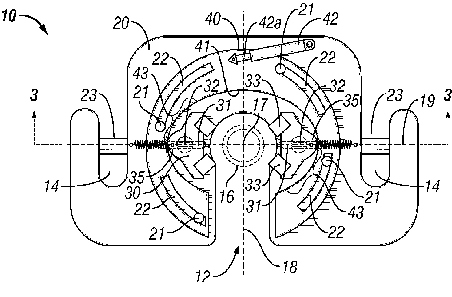
just above the spider. A single joint elevator is used to grip and secure the
segment or stand to a
hoist to lift the segment or stand into position for threadably coupling to
the tubular string.
[0003] For installing a string of casing, existing single joint elevators
generally comprise a
pair of hinged body halves that open to receive a tubular segment and close to
secure the tubular
within the elevator. Elevators are specifically adapted for securing and
lifting tubular members
having conventional connections. A conventional connection comprises an
internally threaded
sleeve that receives and secures an externally threaded end from each of two
tubular segments to
secure the segments in a generally abutting relationship. The internally
threaded sleeve is first
threaded onto the end of a first tubular segment to form a "box end." The
externally threaded
"pin end" of the second tubular segment is threaded into the box end to
complete the connection
between the segments. Typical single joint elevators have a circumferential
shoulder that forms
a circle upon closure of the hinged body halves. The shoulder of the elevator
engages the tubular
segment under a shoulder formed by the end of the sleeve and the tubular
segment. However,
conventional single joint elevators cannot grip a tubular segment having
integral connections,
because there is no sleeve to form a circumferential shoulder.
[0004] Conventional elevators are also difficult to use on tubular segments
that are not
conveniently accessible. For example, casing segments are often moved to the
rig floor from a
1
CA 02687066 2009-11-09
WO 2008/141045 PCT/US2008/062910
horizontal pipe rack and presented to the rig floor at a "V"-door. A
conventional single joint
elevator requires enough clearance to close the hinged body halves around the
tubular segment.
Depending on the length of the tubular and the proximity of the floor or other
rig structures, there
may be insufficient clearance around the circumference of the tubular segment
for gripping with
a conventional single joint elevator, often requiring repositioning of the
casing segment so that
the single joint elevator can grip the tubular segment. Even if repositioning
of each segment
takes only a few seconds, delays for repeatedly repositioning tubular segments
in the V-door
consume a substantial amount of rig time.
[0005] What is needed is a single joint elevator that is securable to a
tubular at any position
along the length of the tubular segment, and not only at the sleeve. What is
needed is a single
joint elevator that is adapted for securing to the tubular segment
notwithstanding close proximity
of the rig floor or other rig structure. What is needed is a single joint
elevator that can grip and
lift single tubular segments without repositioning the tubular segment. What
is needed is a
versatile single joint elevator that facilitates lifting both a tubular
segment having integral
connections and a tubular segment having conventional connections with a
threaded sleeve
received onto the end of a threaded tubular segment.
SUMMARY OF THE PRESENT INVENTION
[0006] The present invention is directed to a single joint elevator for
gripping a tubular
member. The single joint elevator comprises a body having a slot for receiving
a tubular
member. First and second opposing deployable jaws are movably coupled to the
body within the
slot and moveable between a removed position and a deployed position within
the slot, where
each jaw has at least one gripping surface for contacting the tubular member.
An actuator
assembly selectively moves the jaws from the removed position to the deployed
position to grip
and retain the tubular member within the slot of the body while hoisting the
body. The gripping
surface of the jaws may be selected from the group consisting of stationary
gripping dies and
slips. Optionally, the jaws may be outwardly biased, such as with a coil
spring, to return to the
removed position when the actuator assembly is not biasing the jaws inwardly.
[0007] In one embodiment, the actuator assembly includes a cam ring
rotationally coupled to
the body, and an actuator coupled between the body and the cam ring for
imparting rotation of
2
CA 02687066 2009-11-09
WO 2008/141045 PCT/US2008/062910
the cam ring, wherein the cam ring has an inner cam surface for inwardly
biasing the first and
second opposing jaws. The actuator is preferably selected from a linear
actuator and a motor
coupled to the cam ring through a rotary gear. Optionally, the actuator is a
cylinder powered by
a pressurized fluid, such as a double-acting cylinder, for forcibly rotating
the cam ring between a
removed position and a deployed position. The first and second jaws that are
cammed by the
inner cam surface may be pivotally or slidably coupled to the body.
[0008] In a further embodiment, the actuator assembly includes a first
wedge operatively
coupled to a first actuator for selectively biasing the first wedge between
the body and the first
jaw, and a second wedge operatively coupled to a second actuator for
selectively biasing the
second wedge between the body and the second jaw. The first and second
actuators may be
cylinders powered by a pressurized fluid, such a double-acting cylinder for
forcibly moving the
wedges back and forth between a removed position and a deployed position. The
first and
second jaws that engage the wedges may be pivotally or slidably coupled to the
body.
[0009] The foregoing and other objects, features and advantages of the
invention will be
apparent from the following more particular description of a preferred
embodiment of the
invention, as illustrated in the accompanying drawings wherein like reference
numbers represent
like parts of the invention.
BRIEF DESCRIPTION OF THE DRAWINGS
[0010] FIGs. 1-3 are top, side and cross-sectional views of one embodiment
of a single joint
elevator of the present invention having a cam ring that actuates jaws to grip
a tubular segment.
[0011] FIGs. 4-6 are top, side and cross-sectional views of the single
joint elevator of FIGs.
1-3 with the cam ring rotated to an actuated position and the jaws gripping
the tubular segment.
[0012] FIG. 7 is a top view of one embodiment of a single joint elevator of
the present
invention having wedges that actuate pivotable jaws toward a tubular segment.
[0013] FIG. 8 is a top view of the single joint elevator of FIG. 7 with the
wedges actuated to
pivot the jaws into gripping engagement of the tubular segment.
3
CA 02687066 2009-11-09
WO 2008/141045 PCT/US2008/062910
DETAILED DESCRIPTION OF THE PRESENT INVENTION
[0014] The present invention is directed to a single joint elevator for
releasably securing a
tubular segment to a cable, rope, line or other hoisting member for lifting
the tubular segment
into position for being threadably coupled to a pipe string suspended in a
borehole. One
embodiment of the invention comprises a generally horseshoe-shaped body having
a slot for
receiving a tubular segment, and opposing jaws that deploy to grip the tubular
segment within
the slot of the body. The body is adapted for supporting the jaws, and also
for being lifted and
for transferring the weight of the tubular segment to a cable, rope, line or
other hoisting member.
An actuator assembly selectively moves the jaws from a removed position to a
deployed position
to grip and retain the tubular segment within the slot of the body while
hoisting the body. Each
jaw has a removed position permitting entry of the tubular into the slot, and
a deployed position
to grip the tubular within the slot. The deployable jaw is either rotatably or
translatably moved
from its removed position to its deployed position and may be pneumatically,
hydraulically,
and/or electrically actuated.
[0015] The actuator assembly may include a first wedge operatively coupled
to a first
actuator for selectively biasing the first wedge between the body and the
first jaw, and a second
wedge operatively coupled to a second actuator for selectively biasing the
second wedge
between the body and the second jaw. Such an actuator assembly provides
independent
operation of the jaws. Alternatively, the actuator assembly may include a cam
ring rotationally
coupled to the body, and an actuator coupled between the body and the cam ring
for imparting
rotation of the cam ring, wherein the cam ring has an inner cam surface for
inwardly biasing the
first and second opposing jaws. Use of a cam surface allows for coordinated
movement of the
jaws using a single actuator, which may be a pressurized fluid-powered
cylinder or a rotary gear
coupled to a motor.
[0016] In one embodiment, an exemplary cam ring has a generally elliptical
inner cam
surface for symmetrically deploying the gripping jaws upon rotation of the cam
ring in a first
direction and releasing the jaws to retract upon rotation of the cam ring in
the opposite direction.
It should be recognized that a cam ring employing an elliptical cam surface
can deploy the
gripping jaws by rotation of the cam in either direction. The jaws are
deployed when a minor
axis of the cam surface ellipse is rotationally biased toward the jaw, because
the jaw is restrained
4
CA 02687066 2009-11-09
WO 2008/141045 PCT/US2008/062910
from rotating with the cam and is gradually biased toward the center of the
ellipse. The jaws are
able to move to a fully removed position when the cam is rotated to a point
where the major axis
of the ellipse is aligned with the jaws. The eccentricity of the cam surface
effects both the
maximum distance that the jaws can be moved together (i.e., the difference in
the lengths of the
between the major and minor axis) and also the amount of cam rotating force
that will be
transferred to the jaws as a gripping force. It should also be recognized that
the cam surface does
not need to be a true ellipse, but may have any profile that is designed to
achieve sufficient jaw
travel and gripping forces. Furthermore, the cam surface may be interrupted or
fragmented,
since it is anticipated that the cam ring will typically not be rotated more
than about 45 degrees
in either direction from the major axis. Furthermore, the cam surface does not
need to be
"double-acting" as an elliptical surface extending in either direction from
the major axis, but
could be "single acting" with a gradually reducing radial distance in only one
rotational
direction. A single acting cam ring should include a separate single acting
cam surface for each
jaw and should be pitched for coordinated simultaneous deployment with a
single actuator. For
example, even a continuous elliptical surface that has the potential to be
"double-acting" will
preferably have its rotation limited so that the cam surface functions as a
single-acting cam
surface. Rotational limits increase the accuracy and reliability of
positioning the cam ring with
the jaws in the fully removed position.
[0017] Each jaw is moveably supported by the body. Preferably, the jaws are
either pivotally
or slidably coupled to the body. Accordingly, the actuator assembly engages
and biases the jaws
to pivot or to slide from a removed position to a deployed position to grip
the tubular.
[0018] Each deployable jaw preferably comprises a slip or gripping die. In
one embodiment,
gripping dies are pivotally secured to the jaw and rotating toward the tubular
to tighten the grip.
The jaws may have sloped-back inserts that are spring offset upward. Once the
jaws have been
energized against the tubular segment, the weight of the tubular segment will
force the inserts
downward and into the tubular wall. In another embodiment, each jaw comprise
one or more
grooves for slidably receiving tabs, keys, or guides for imposing a
predetermined path for
movement of a slip within the jaw. Each slip may comprises a contact surface,
such as a
removable insert or gripping die, which may comprise a textured surface
adapted for gripping
contact with the external wall of the tubular segment received into the slot.
CA 02687066 2009-11-09
WO 2008/141045 PCT/US2008/062910
[0019] As used herein, the term "single joint elevator" is intended to
distinguish the elevator
from a string elevator that is used to support the weight of the entire pipe
string. Rather, a
"single joint elevator" is used to grip and lift a tubular segment as is
necessary to add or remove
the tubular segment to or from a tubular string. Furthermore, a pipe or
tubular "segment", as that
term is used herein, is inclusive of either a single pipe or tubular joint or
a stand made up of
multiple joints of a pipe or other tubular that will be lifted as a unit. In
the context of the present
disclosure, a tubular segment does not include a tubular string that extends
into the well.
[0020] FIG. 1 is a top view of one embodiment of a single joint elevator
having a cam ring
that actuates opposing jaws to grip a tubular segment. The single joint
elevator 10 has a
generally horseshoe-shaped body 20 that is securable to one or more cables,
ropes, lines or other
hoisting members (not shown) at a pair of generally opposed lugs 23 to
facilitate lifting and
positioning of the single joint elevator 10 and any tubular segment 16 secured
therein. The lugs
23 may be removable and replaceable to facilitate securing the single joint
elevator 10 to a loop
formed in the end of a cable.
[0021] The body 20 has a slot 12 in one side for receiving the tubular
segment 16 and
supports a cam ring 40 for selective rotation generally about an axis 17 of
the cam ring. The
central axis of the cam ring 40 is preferably positioned to substantially
intersect a centerline 18
of the slot 12 in order to receive the tubular segment generally centered
within the cam ring 40.
It is also preferable for the axis 17 of the cam ring 40 to be positioned to
substantially intersect a
line 19 extending between the lugs 23 so that once the concentrically received
tubular segment
has been gripped and lifted, the tubular segment will hang straight downward.
[0022] The cam ring 40 includes a plurality of slots 22, each slot having a
constant radius of
curvature about the axis of rotation 17. Each slot 22 slidably receives a post
21 that is fixedly
secured to the body 20 and positioned to allow the cam ring 40 to rotate
relative to the body 20,
while preventing translation of the cam ring 40 relative to the body. It is
preferable to limit the
arc of the slot 22 to about 30 to 45 degrees in order to limit the extent to
which the cam ring 40
will rotate relative to the body 20 and avoid weakening of the cam ring 40.
One reason to limit
rotation of the cam ring 40 is to prevent the possibility that over-rotation
of the cam ring 40 will
cause an unintended re-deployment of the jaws 30. Accordingly, it should be
recognized that the
6
CA 02687066 2009-11-09
WO 2008/141045 PCT/US2008/062910
slots 22 and posts 21 cooperate to allow only portions 43 of the inner cam
surface 41 to operate
and cam the jaws 30.
[0023] A cylinder 42 has a first end pivotally secured to the body 20 and a
second end
pivotally secured to the cam ring 40. Applying fluid pressure within the
cylinder 42 causes the
cylinder rod 42a to extend. Because the cam ring 40 is rotationally secured,
the extension of the
cylinder 42, as configured in FIG. 1 and viewed from the top, causes the cam
ring 40 to rotate in
a counter-clockwise direction about the axis of rotation 17 and move the jaws
30 to a deployed
position (see FIG. 4). Subsequent retraction of the cylinder 42 causes the cam
ring to rotate in
the opposite, or clockwise direction back to the removed position shown in
Fig. 1.
[0024] First and second jaws 30 are each slidably secured to the body 20
using a pin, tongue,
or blade 32 that extends into a slot, groove, or track 31 in the body. The
tracks 31 are directed
toward the axis of rotation 17 to allow the jaw 30 to deploy between a removed
position (as
shown in FIG. 1) and a deployed position (with jaws 30 displaced one toward
the other) to grip
the pipe 16 (as shown in FIG. 4). Each jaw 30 includes one or more slips or
other gripping
members 33 secured to an inwardly facing surface of the jaw 30 for contacting
and gripping the
tubular segment. The outwardly facing side of each jaw 30 forms a cam follower
35 that slidably
engages the inner cam surface 41 of the cam ring 40.
[0025] FIG. 2 is a front elevation view of the single joint elevator 10
having a cam ring 40
that rotates to actuate jaws 30 (See FIG. 1) to grip a tubular segment 16. The
slotted body 20 and
slotted cam ring 40 are shown in alignment to provide an open slot 12 for
receiving a tubular
segment 16.
[0026] FIG. 3 is a front cross-sectional view of the single joint elevator
10 taken along line
3-3 in FIG. 1. This view highlights the lugs 23 for supporting the body 20 and
the tubular
gripped therein, and the slots or track 31 within the body 20 that slidably
secure the jaws 30.
Each jaw 30 includes a blade, tongue, or post 32 that is received in a slot,
grove or track 31 and,
in Fig. 3 is secured vertically by a head 30a that is larger than the width of
the slot. This
configuration allows the jaw 30 of Fig. 3 to slide along the path of the track
31 (left and right as
shown in FIG. 3). While the jaw 30 is preferably prevented from any large
degree of rotation
about its post 32 to avoid mis-engagement of the slips 33 against the tubular
segment 16, a few
degrees of permitted rotation may be desirable to allow the jaws to self-align
with the tubular
7
CA 02687066 2009-11-09
WO 2008/141045 PCT/US2008/062910
segment 16. A post 32 having a circular cross-section will enable rotation of
the jaw 30 about
the post, but this must be otherwise limited such as by the outward face of
the jaw 30 being
configured to engage the cam surface 41. Furthermore, the rotation of the jaw
30 can be limited
by replacing post 32 with a blade that is longer than width of the track 31 so
that the blade 32 can
rotate only a few degrees within the track 31.
[0027] FIG. 4 is a top view of the single joint elevator 10 with the cam
ring 40 rotated to a
deployed position and the jaws 30 gripping the tubular segment 16. The
cylinder 42 has been
extended under fluid pressure to bias the cam ring 40 to rotate counter-
clockwise relative to the
body 20 about 35 degrees, wherein the rotation of the cam ring 40 is guided by
the slots 22
slidably secured about the posts 21. This rotation of the cam ring 40 causes
the inner cam
surface 41 to push the jaws 30 along the tracks 31 inwardly toward the axis 17
until the slips 33
engage and grip the tubular segment 16. Continued application of fluid
pressure to the cylinder
42 maintains this grip on the tubular segment 16 during handling of the
tubular segment.
[0028] When the handling of the tubular segment has been completed, the
single joint
elevator 10 is released from the tubular segment 16 by retracting the cylinder
42 to the position
of FIG. 1. Since the jaws 30 are then no longer biased inwardly by the cam
surface 41, the jaws
move away from the tubular segment to a removed position under the action of
springs 34. The
jaw 30 may be biased away from engagement with the tubular segment in other
manners, such as
by slidably coupling a "T"-shaped bar attached to the jaw 30 within a "T"-
shaped receiving
groove formed in the inner cam surface 41.
[0029] FIG. 5 is a side view of the single joint elevator 10 with the cam
ring 40 rotated to an
actuated position and the jaws 30 gripping the tubular segment 16. The slot in
the cam ring 40 is
now shown radially offset from the slot 12 in the body 20, such that the
single joint elevator 10 is
closed.
[0030] FIG. 6 is a cross-sectional view of the single joint elevator 10,
taken along line 6-6 in
FIG. 4. Counter-clockwise rotation of the cam ring 40 has caused the inner cam
surface 41 to
push the cam follower 35 of the jaws 30 inwardly toward to tubular segment 16.
The post 32 has
traveled inwardly along the track 31 with the cam rotated to an actuated
position and the jaws 30
gripping the tubular segment.
8
CA 02687066 2009-11-09
WO 2008/141045 PCT/US2008/062910
[0031] FIG. 7 is a top view of a second embodiment of a single joint
elevator 50 having
translatably deployable wedges 52 that engage and actuate pivotable jaws 54
toward a tubular
segment 16 received within the slots 12 of body 20. The body 20 pivotally
secures first and
second jaws 54 at pivots 56, which preferably include a coil spring 58 for
biasing the jaws 54
toward the removed position (as shown in Fig. 7). With the jaws 54 in the
removed position, the
slot 12 may receive a tubular segment 16 without the jaws 54 either blocking
the slot or being in
a position to be hit as the tubular segment 16 is received. The wedges 52 are
slidably secured
between the back of the jaws 54 and backing stops 60. Cylinders 62 secured to
the body 20 at
pins 62a may be used to selectively bias the wedges 52 between retracted and
extended positions
to move the wedges 52 between removed (see FIG. 7) and deployed (see FIG. 8)
positions,
respectively. While the cylinders 62 may be independently controlled with
fluid pressure, the
cylinders are preferably actuated simultaneous by providing them on the same
fluid power line.
[0032] FIG. 8 is a top view of the single joint elevator 50 of FIG. 7 with
the wedges 52
extended to pivot the jaws 54 about the pivots 56 and bias the jaws 54 into
gripping engagement
of the tubular segment 16. The slips 33 on the jaws 54 are arranged to contact
and grip the outer
surface of the tubular segment. Continued application of fluid pressure to the
cylinders 62
maintains this grip on the tubular segment 16 during handling of the tubular
segment.
Alternately, the cylinder rods 62b or the wedges 52 may be mechanically locked
into the
deployed condition using a latch to maintain the grip on the tubular segment
16 even if the
hydraulic pressure is lost or reduced.
[0033] When the handling of the tubular segment has been completed, the
single joint
elevator 50 is released from the tubular segment 16 by retracting the cylinder
62 to the position
of FIG. 7. Since the jaws 54 are then no longer biased inwardly by the wedges
52, the jaws
move away from the tubular segment to a removed position under the action of
springs 34. The
jaw may be biased away from the tubular segment in various ways, but a coil
spring 56 is easily
implemented.
[0034] The terms "comprising," "including," and "having," as used in the
claims and
specification herein, indicate an open group that includes other elements or
features not
specified. The term "consisting essentially of," as used in the claims and
specification herein,
indicates a partially open group that includes other elements not specified,
so long as those other
9
CA 02687066 2014-09-02
,
elements or features do not materially alter the basic and novel
characteristics of the claimed
invention. The terms "a," "an" and the singular forms of words include the
plural form of the
same words, and the terms mean that one or more of something is provided. The
terms "at least
one" and "one or more" are used interchangeably.
[0035]
The term "one" or "single" shall be used to indicate that one and only one
of
something is intended. Similarly, other specific integer values, such as
"two," are used when a
specific number of things is intended.
The terms "preferably," "preferred," "prefer,"
"optionally," "may," and similar terms are used to indicate that an item,
condition or step being
referred to is an optional (not required) feature of the invention.
[0036]
It should be understood from the foregoing description that various
modifications and
changes may be made in the preferred embodiments of the present invention. The
foregoing
description is provided for the purpose of illustration only.