Note : Les descriptions sont présentées dans la langue officielle dans laquelle elles ont été soumises.
CA 02687072 2009-11-10
WO 2008/140880 PCT/US2008/060109
SYSTEM AND METHOD FOR ESTIMATING THE LOCATION OF A MOBILE
STATION IN COMMUNICATIONS NETWORKS
Related Applications
[0001] The instant application is co-pending and related to U.S. Application
No.
11/749,095, filed May 15, 2007, entitled "System and Method for Network Timing
Recovery in Communications Networks," the entirety of which is incorporated
herein by
reference.
Background
[0002] A number of applications currently exist within communication systems,
such as those supporting Global System for Mobile Communication ("GSM"), Time
Division Multiple Access ("TDMA"), Code Division Multiple Access ("CDMA") and
Universal Mobile Telecommunications System ("UMTS") technologies, for which
precise
common timing information is needed by mobile units and by other entities in a
wireless
network. Examples of such applications include GSM positioning and assisted
global
positioning system ("A-GPS") positioning. Mobile units with A-GPS acquire and
measure
signals from a number of GPS satellites in order to obtain an accurate
estimate of their
current geographic position. It is well known that precise knowledge of GPS
time can
greatly improve positioning measurements for higher sensitivity in otherwise
poor signal
areas, e.g., indoors or urban areas where a GPS satellite signal may be
blocked. Another
application would be accurate time stamping of significant events (e.g. alarms
and faults)
by network entities such that events emanating from the same cause but
registered in
different entities could more easily be associated through their common time
of
occurrence.
[0003] In some wireless technologies, e.g., CDMA, the transmission timing of
all
base stations has to be precisely and explicitly synchronized to a common time
source,
such as a Global Positioning System ("GPS") originated clock. Such a precise
transmission timing clock provides wireless terminals with unrestricted access
to precise
common timing information without any special additional support. In other
technologies,
like GSM and TDMA, each base station maintains its own local timing source,
which,
1
CA 02687072 2009-11-10
WO 2008/140880 PCT/US2008/060109
though precise within its own frame of reference, does not indicate a
particular universal
time nor align with the timing maintained by other base stations.
[0004] Providing precise common timing information for GSM, TDMA or UMTS
base stations may require deploying additional units such as Location
Measurement Units
("LMU") that measure and associate the transmission timing of one or more base
stations
with a common timing source. Generally, an LMU is a device that measures the
downlink
timing of each base station, relative to a stable time base such as GPS,
either through a
direct RF connection in the base station, or through an over the-air, antenna
based
connection. The precise association of the local timing of each base station
with the
common timing source may be passed to mobile units and base stations for
deriving
accurate timing, according to the common timing source, from the local
transmission
timing of a particular base station, e.g., the base station serving a
particular mobile unit.
GSM LMUs tend to require additional hardware and are expensive additions in
any
wireless network. Moreover, in order to synchronize the transmission timing of
every
wireless network base station with a common timing source, it may be necessary
to deploy
a separate measurement unit for every base station, or every few base
stations, thereby
further increasing cost and deployment time.
[0005] There exists a need in the art to locate UMTS or W-CDMA mobile devices
to satisfy FCC E-911 regulations as well as to provide Location Based Services
for mobile
phone users. The 3GPP UMTS standard outlines several methods for location
including
Cell-ID, A-GPS, Observed Time Difference of Arrival ("OTDOA"), and Uplink Time
Difference of Arrival ("U-TDOA"). Cell-ID generally is the simplest method
which
provides coarse positioning of mobile devices based on a known location of the
coverage
area centroid of each base station sector. Additionally, A-GPS is a
straightforward
implementation for network and handset manufacturers due to their legacy in
CDMA2000
networks. Likewise, U-TDOA is also a straightforward technique for those
skilled in the
art and has been widely deployed for other air standards. OTDOA, on the other
hand, is
confronted with significant implementation challenges for carriers, due to the
fact that the
base station timing relationships must be known, or measured, for this
technique to be
2
CA 02687072 2009-11-10
WO 2008/140880 PCT/US2008/060109
viable. For unsynchronized UMTS networks, where the base station timing is not
locked
to.a common timing source, the 3GPP standard offers the suggestion that base
station
LMUs may be utilized to recover this timing information. Once the base station
timing
relationships are measured, the handset measurements of Observed Time
Difference
("OTD") between various base stations may be translated into absolute range
differences
from which position can be calculated (e.g., through user equipment ("UE")-
based or UE-
assisted methods).
[0006] There appears to be little interest by network operators in
implementing the
OTDOA solution. This may be due to a general lack of cost-effective solutions
for
practical implementations of OTDOA in unsynchronized UMTS networks,
significant
hardware, installation, testing, and maintenance costs associated with L1VIUs,
and/or a lack
of available LMU vendors. Further, the lack of interest by network operators
in
implementing the OTDOA solution may also be due to a lack of handset
manufacturers
implementing-OTDOA measurements into the associated firmware, negative
perception of
OTDOA due to the potential network capacity impacts if Idle Period Downlink
("IPDL")
is enabled by carriers, and/or carrier perception that A-GPS handsets will
meet all the
location needs of its users.
[0007] Accordingly, there is a need for a method and system for location and
network timing recovery in communications networks. Therefore, an embodiment
of the
present subject matter provides a method for estimating the location of a
mobile station
that receives signals from a plurality of base stations. The method comprises
the steps of
determining an estimated location of a first mobile station and utilizing a
first set of
network measurements such as OTD values at the first mobile station between a
first
signal received from a first base station and a second signal received from a
second base
station. A network timing value may be determined as a function of the
estimated location
and OTD values and an estimated location of a second mobile station may be
determined
as a function of the network timing value. Another embodiment of the present
subject
matter may update the network timing value as a function of a base station
time offset drift
value for a base station time offset between the first and second base
stations.
3
CA 02687072 2009-11-10
WO 2008/140880 PCT/US2008/060109
[0008] Another embodiment of the present subject matter provides a method for
estimating the location of a mobile station that receives signals from a
plurality of base
stations. The method comprises the steps of determining an estimated location
of a first
mobile station, utilizing a first set of network measurements such as OTD
values at the
first mobile station between a first signal received from a first base station
and a second
signal received from a second base station, and utilizing a second set of
network
measurements such as RTT values at the first mobile station or base stations
in the
network. A network timing value may be determined as a function of the
estimated
location and the first and second set of network measurements and an estimated
location of
a second mobile station may be determined as a function of the network timing
value. An
additional embodiment of the present subject matter may update the network
timing value
as a function of a base station time offset drift value for a base station
time offset between
the first and second base stations.
[0009] A further embodiment of the present subject matter provides a system
for
estimating the location of a mobile station that receives signals from a
plurality of base
stations. The system may comprise circuitry for determining an estimated
location of a
first mobile station and circuitry for utilizing a first set of network
measurements such as
OTD values at the first mobile station between a first signal received from a
first base
station and a second signal received from a second base station. The system
may further
comprise circuitry for determining a network timing value as a function of the
estimated
location and OTD, and circuitry for determining an estimated location of a
second mobile
station as a function of the network timing value. An additional embodiment of
the
present subject matter may provide circuitry for updating the network timing
value as a
function of a base station time offset drift value for a base station time
offset between the
first and second base stations. An alternative embodiment of the present
subject matter
may provide circuitry for transmitting the estimated location and network
measurements to
a communications network wherein the network determines the network timing
values.
Additional embodiments of the present subject matter may provide circuitry for
transmitting the estimated location and network measurements to a system
remote from
the communications network where the system determines the network timing
values.
4
CA 02687072 2009-11-10
WO 2008/140880 PCT/US2008/060109
[0010] A further embodiment may also comprise circuitry for utilizing a second
set
of network measurements such as RTT values at the first mobile station or base
stations in
the network.
[0011] These embodiments and many other objects and advantages thereof will be
readily apparent to one skilled in the art to which the invention pertains
from a perusal of
the claims, the appended drawings, and the following detailed description of
the
embodiments.
Brief Description of the Drawings
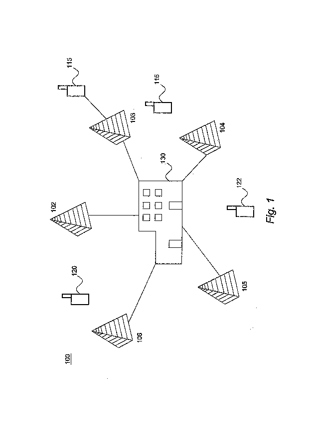
[0012] Figure 1 is an illustration of a wireless communications network.
[0013] Figure 2 is an algorithm according to one embodiment of the present
subject
matter.
[0014] Figure 3 is an algorithm according to a further embodiment of the
present
subject matter.
[0015] Figure 4 is an algorithm according to another embodiment of the present
subject matter.
Detailed Description
[0016] With reference to the figures where like elements have been given like
numerical designations to facilitate an understandirig of the present subject
matter, the
various embodiments of a system and method for location and network timing
recovery in
communications networks are described.
[0017] Embodiments of the present subject matter overcome the challenges
associated with implementing non Assisted Global Positioning System ("A-GPS")
based
location methods in unsynchronized Universal Mobile Telecommunications System
("UMTS") networks. Embodiments of the present subject matter also derive and
maintain
base station timing relationships from a mobile device, station or handset
measured
Observed Time Differences ("OTD"). The terms "device", "handset" and "station"
are
CA 02687072 2009-11-10
WO 2008/140880 PCT/US2008/060109
utilized interchangeably through the present disclosure and such use is not
intended to
limit the scope of the claims appended herewith. Handset OTDs may be derived
through
periodic measurement reporting needed to support on-going radio link
communications as
well as through explicit, event-driven measurement reporting requested by the
network.
For mobile unit location determination, however, handset OTDs are meaningless
without
knowledge of underlying base station timing relationships.
[0018] Embodiments of the present subject matter also provide alternate
methods to
derive base station timing information. Thus, once the base station timing
relationships
are known, the positions of either the same mobile device or other mobile
devices may be
calculated completely, or partly, from the OTDs at a later time. This aspect
of the present
subject matter provides that location capability may be available to non-A-GPS
handsets
in a network and that high volume mobile device location may be easily
computed through
existing network handset measurements without consuming the time, battery,
and/or
network capacity associated with A-GPS position estimation. The latter is a
sought after
requirement for enhanced network optimization utilizing geo-coded
measurements, as well
as. for security applications requiring frequent position updates for all
active users in a
network. Another aspect of the present subject matter provides an accurate
fallback
location method when other methods, such as A-GPS, fail. It is anticipated
that A-GPS
yield will be poor in areas where open-sky conditions do not exist, e.g.,
indoors and urban
environments. While A-GPS is designed to improve yield in such conditions,
many
scenarios exist in where A-GPS may not provide enough gain over conventional
GPS to
produce a successful A-GPS fix. Furthermore, base station time relationships
tend to drift
over time as a function of oscillator characteristics utilized in the
respective base stations.
This drift must also be accounted for when utilizing these methods, either
through periodic
updating of the estimated base station time relationships (base station timing
offsets or
"BSTO") or through known means to track and predict timing relationships via
prediction
methods based on past measurement timing trends. Exemplary means of prediction
are
well-known in the industry and are a manageable problem to those skilled in
the art, and
will thus not be the subject of further discussion herein.
6
CA 02687072 2009-11-10
WO 2008/140880 PCT/US2008/060109
[0019] OTDs generally define a set of handset based measurements known in the
3GPP standard such as System Frame Number "SFN-SFN" Type 1 and/or Type 2.
These
measurements are generally the observed time difference of two base station
cells or
sectors and differ primarily in the timing resolution of the measurements. For
example,
with Type 1, a mobile device measures the timing difference between the
Primary
Common Control Physical Channels ("P-CCPCH") of cell 1 and cell 2. Type 1 is
generally available on a CELL FACH connection. While a soft handover cannot be
performed while on a CELL FACH connection, the network may request the mobile
device to measure the timing difference between cell 1 and cell 2. While on a
CELL FACH connection, a Measurement Control Message may be sent to the mobile
device on the Forward Access Channel ("FACH"), and the mobile device's
measurement
results are returned on the Reverse Access Channel ("RACH"). With Type 2, the
mobile
device measures the timing difference between the Common Pilot Channels
("CPICH") of
cell 1 and ce112. Type 2 is applicable to both CELL DCH and CELL FACH
connections.
With either connection type, if there is power in cell 2, the mobile may
measure the timing
difference between the two cells. While on a CELL DCH connection, the mobile
device
may measure OTDs while in soft handover with cells 1 and 2: Another set of
handset
based measurements known in the 3GPP standard is SFN-Connection Frame Number
("CFN"). These measurements refer to the observed time difference between the
connection to a current serving base station cell and some set of handset-
measurable,
neighboring cells or sectors.
[0020] Providing that a given network employs A-GPS capability and that some
number of A-GPS capable mobile devices exist in the network, embodiments of
the
present subject matter may pair A-GPS derived handset locations and the
coincidental
OTD measurements made against various nearby base stations. Once the handset
location
is known, the base station timing relationships may be directly derived from
the OTDs.
Further embodiments may utilize other standardized network measurements. For
example,
Round Trip Time ("RTT") is a standardized network measurement that may be
determined
from one or more base stations in communication with a particular mobile
device. If the
mobile device is in soft handoff with at least three base stations, a position
may be
7
CA 02687072 2009-11-10
WO 2008/140880 PCT/US2008/060109
determined for that mobile device from the various RTTs. Given that the
handset OTDs
may be concurrently measured, this provides an opportunity to compute the base
station
time relationships given that the mobile location is now known. Thus, mobile
location
with a single ambiguity may be calculated with as few as two RTTs.
Furthermore, such an
embodiment may be improved if one of the ambiguous locations may be eliminated
based
upon other available information such as sector orientations and received
power levels
from those sectors.
[0021] In networks employing an Uplink Time Difference of Arrival ("U-TDOA")
location system, base station timing relationships may be derived from the
concurrently
measured handset OTDs from positions calculated by the U-TDOA system. An
alternative
method to derive base station timing relationships may be to deploy some
number of
mobiles into known locations throughout the network, where the positions
thereof are
unchanging and known. Provided that these mobiles are placed in positions
allowing them
to observe multiple OTDs, these mobiles may be utilized by the network to
determine the
base station timing relationships since the position from which the
measurements were
taken is known.
[0022] Additional embodiments of the present subject matter may determine base
station timing relationships by deploying some number of cooperative mobile
devices or
other measurement devices in either stationary or mobile environments. These
devices
may be equipped with GPS positioning or some other accurate location means,
make OTD
measurements, and provide these measurements to the network in conjunction
with their
kri.own positions to thereby allow the network to derive the applicable base
station timing
relationships. An exemplary device may be, but is not limited to, a UMTS
mobile
connected to a GPS receiver, where the coordinates of the GPS position may be
periodically relayed to the network along with the OTDs. Deployment of such
devices
may occur upon buses, taxis, or other vehicles or in stationary locations.
Further methods
to determine location of mobile devices by embodiments of the present subject
matter may
be through various pattern matching methods that pair sets of measurements
observed by a
mobile device in the network to geographical position. Exemplary handset
observed
8
CA 02687072 2009-11-10
WO 2008/140880 PCT/US2008/060109
measurements may be, but are not limited to, a set of received signal
strengths, transmit
power, calculated path losses, active, detected, and monitored pilot sets,
multi-path
propagation profiles, and the like. Once a mobile device's location is
determined through
pattern matching of measurements to location, concurrent OTDs measured by the
mobile
device may be utilized to determine the base station timing relationships.
Other
embodiments of the present subject matter may utilize hybrid methods to
recover base
station timing relationships, e.g., pattern matching may be combined with RTT
and/or
cooperative mobile devices, etc. Thus, as long as there are sufficient
measurements from
which locations could be computed, concurrently measured OTDs may be utilized
to
derive the base station timing relationships. Further, any of the
aforementioned
embodiments in conjunction with the deployment of some number of network
Location
Measurement Units ("LMU") may provide mobile location estimates, and hence
derive the
base station timing relationships from the handset OTDs. It is thus an aspect
of the present
subject matter that any location means or technology, when paired with handset
OTDs,
may be utilized to derive and maintain on an on-going basis network base
station timing
relationships.
[0023] Figure 1 is an illustration of a wireless communications network. With
reference to Figure 1, a wireless communications network 100 or system is
shown. The
network may be a Global System for Mobile Communication ("GSM") network, a
Time
Division Multiple Access ("TDMA") network, Code Division Multiple Access
("CDMA")
network, a UMTS network, a Worldwide Interoperability for Microwave Access
("WiMax") network, a WiFi network, networks utilizing Evolution-Data Optimized
("EDVO"), CDMA2000 network, 1 times Radio Transmission Technology ("1xRTT")
standards or another equivalent network.
. [0024] Location measurement units ("LMU") 115 may be dispersed throughout
the
system or subsystem reception area. These LMUs 115 may be integrated with a
base
station 102-106 or may be independent of a base station 102-106. The wireless
network
100 serves mobile stations or devices 120, 122 within reception range of at
least one of the
base stations 102-106. Mobile stations 120, 122 may include cellular
telephones, text
9
CA 02687072 2009-11-10
WO 2008/140880 PCT/US2008/060109
messaging devices, computers, portable computers, vehicle locating devices,
vehicle
security devices, communication devices, wireless transceivers or other
devices with a
wireless communications interface. Base station transceivers 102-106, also
commonly
referred to simply as base stations, are connected to a central entity or
central network unit
130. The central entity 130 may be a base station controller ("BSC") in a base
station
subsystem ("BSS"), a Radio Network Controller ("RNC") in a Radio Access
Network
("RAN"), or, for GSM, General Packet Radio Service ("GPRS") or UMTS system, a
serving mobile location center ("SMLC") or an equivalent. The connection from
each
base station to a BSC, SMLC or other central network entity may employ a
direct
transmission link, e.g., a wired connection, microwave link, Ethernet
connection, and the
like, or may be employed by one or more intermediate entities, e.g., an
intermediate BSC
in the case of a connection from a BTS to an SMLC for GSM.
[0025] Each mobile station 120, 122 may periodically measure the transmission
timing difference between pairs of base stations 102-106. For example, a
mobile station
120 may measure the difference in transmission timing for communication from
its
serving base station 102 and from one or more neighboring base stations, e.g.,
106 and/or
103. Either the mobile station or the base station may remove differences
attributed
primarily to propagation delays between the mobile station and base station
antennas to
produce a timing difference.
[0026] Figure 2 is an algorithm according to one embodiment of the present
subject
matter. With reference to Figure 2, a method for determining the network
timing of a
communications network from a mobile station receiving signals from a
plurality of base
stations is provided. Exemplary communications networks may be a UMTS network,
WiMax network, GSM network, WiFi network, CDMA network or a network utilizing
EDVO, CDMA2000, 1xRTT standards. However, the aforementioned examples are not
intended to limit the scope of the claims appended herewith. In step 210, an
estimated
location of a mobile station or device may be determined. An exemplary mobile
station
may be, but is not limited to a cellular telephone, text messaging device,
computer,
portable computer, vehicle locating device, vehicle security device,
communication
CA 02687072 2009-11-10
WO 2008/140880 PCT/US2008/060109
device, and wireless transceiver. The estimated location may be determined as
a function
of an OTDOA, RTT, signal strength and/or Cell-ID values. Appropriate values
may be
observed by the mobile device and/or the network. Additionally, the estimated
location
may be determined as a function of signals received from a positional
satellite system such
as GPS or may be determined as a function of signals received from one or more
LMUs
installed throughout the network. These LMUs may be co-located at a base
station or may
be provided locations separate from a base station. In alternative embodiments
the mobile
station may be a cooperative mobile station or other measurement device
positioned at a
known geographic location. Additional embodiments may determine mobile device
location as a function of a location system that locates rnobile devices
through a hybrid
combination of location technologies such as triangulation, trilateration,
time difference of
arrival, GPS, angle of arrival, Cell-ID, signal strength, assisted-GPS,
Enhanced Observed
Time Difference, Advanced Forward Link Trilateration.
[0027] A first set of network measurements such as OTD values may be utilized
at
the mobile station between a first signal received from a first base station
and a second
signal received from a second base station as represented in step 220. As
previously
described, these OTD values may be SFN-SFN Type 1, SFN-SFN Type 2, or SFN-CFN
and may be determined periodically or by a request transmitted from said
communication
network. Furthermore, the first and second base stations may or may not be
synchronized.
Additionally the first and second base stations are loosely synchronized,
i.e.,
synchronization between the base stations is not maintained to within
approximately one
hundred nanoseconds or less. The first base station may be, but is not limited
to, the
serving base station for the mobile. Further, the first and second base
stations may be
located in different or the same sectors or cells.
[0028] A second set of network measurements such as RTT values may be utilized
at the mobile station or base stations in the network in step 230. Network
timing
relationships may then be determined as a function of the estimated location
and the OTD
and RTT values in step 240. An alternative embodiment of the present subject
matter may
also update the network timing value as a function of a base statiori time
offset drift value
11
CA 02687072 2009-11-10
WO 2008/140880 PCT/US2008/060109
for a base station time offset between the first and second base stations. The
estimated
loaation and network measurements may also be transmitted to the
communications
network or to a system remote from the communications network where the
network
determines the network timing values in additional embodiments of the present
subject
matter.
[0029] Figure 3 is an algorithm according to a further embodiment of the
present
subject matter. With reference to Figure 3, a method for estimating the
location of a
mobile station that receives signals from a plurality of base stations is
provided. The base
stations may be operable in a communications network such as, but not limited
to, a
UMTS network, WiMax network, GSM network, WiFi network, CDMA network or a
network utilizing EDVO, CDMA2000, or 1xRTT standards. In step 310, an
estimated
location of a first mobile station is determined. An exemplary mobile station
may be, but
is not limited to a cellular telephone, text messaging device, computer,
portable computer,
vehicle locating device, vehicle security device, communication device, and
wireless
transceiver. The estimated location may be determined as a function of an
OTDOA, RTT,
signal strength and/or Cell-ID values. Appropriate values may be observed by
the mobile
device and/or the network. Additionally, the estimated location may be
determined as a
function of signals received from a positional satellite system such as GPS or
may be
determined as a function of signals received from one or more LMUs installed
throughout
the network. These LMUs may be co-located at a base station or may be provided
locations separate from a base station. In alternative embodiments the mobile
station may
be a cooperative mobile station or other measurement device positioned at a
known
geographic location. Additional embodiments may determine mobile device
location as a
function of a location system that locates mobile devices through a hybrid
combination of
location technologies such as triangulation, trilateration, time difference of
arrival, GPS,
angle of arrival, Cell-ID, signal strength, assisted-GPS, Enhanced Observed
Time
Difference, Advanced Forward Link Trilateration.
[0030] Network measurements such as OTD values may be utilized at the first
mobile station between a first signal received from a first base station and a
second signal
12
CA 02687072 2009-11-10
WO 2008/140880 PCT/US2008/060109
received from a second base station as represented in step 320. As previously
described,
these OTD values may be SFN-SFN Type 1, SFN-SFN Type 2, or SFN-CFN and may be
determined periodically or by a request transmitted from said communication
network.
Furthermore, the first and second base stations may or may not be
synchronized.
Additionally the first and second base stations are loosely synchronized. The
first base
station may be, but is not limited to, the serving base station for the
mobile. Further, the
first and second base stations may be located in different or the same sectors
or cells.
[0031] Network timing relationships may be determined as a function of the
estimated location and the OTD in step 330. In step 340, an estimated location
of a second
mobile station may then be determined as a function of the network timing
relationships.
An alternative embodiment of the present subject matter may also update
network timing
relationships as a function of a base station time offset drift value for a
base station time
offset between the first and second base stations. The estimated location and
network
measurements may also be transmitted to the communications network or to a
system
remote from the communications network where the network determines the
network
timing values in additional embodiments of the present subject matter.
[0032] Figure 4 is an algorithm according to another embodiment of the present
subject matter. With reference to Figure 4, a method for estimating the
location of a
mobile station that receives signals from a plurality of base stations is
provided. The base
stations may be operable in a communications network such as, but not limited
to, a
UMTS network, WiMax network, GSM network, WiFi network, CDMA network or a
network utilizing EDVO, CDMA2000, or lxRTT standards. In step 410, an
estimated
location of a first mobile station is determined. An exemplary mobile station
may be, but
is not limited to a cellular telephone, text messaging device, computer,
portable computer,
vehicle locating device, vehicle security device, communication device, and
wireless
transceiver. The estimated location may be determined as a function of an
OTDOA, RTT,
signal strength and/or Cell-ID values. Appropriate values may be observed by
the mobile
device and/or the network. Additionally, the estimated location may be
determined as a
function of signals received from a positional satellite system such as GPS or
may be
13
CA 02687072 2009-11-10
WO 2008/140880 PCT/US2008/060109
determined as a function of signals received from one or more L1VIUs installed
throughout
the network. These L1VIUs may be co-located at a base station or may be
provided
locations separate from a base station. In alternative embodiments the mobile
station may
be a cooperative mobile station or other measurement device positioned at a
known
geographic location. Additional embodiments may determine mobile device
location as a
function of a location system that locates mobile devices through a hybrid
combination of
location techriologies such as triangulation, trilateration, triangulation,
time difference of
arrival, GPS, angle of arrival, Cell-ID, signal strength, assisted-GPS,
Enhanced Observed
Time Difference, Advanced Forward Link Trilateration.
[0033] A first set of network measurements such as OTD values may be utilized
at
the first mobile station between a first signal received from a first base
station and a
second signal received from a second base station as represented in step 420.
As
previously described, these OTD values may be SFN-SFN Type 1, SFN-SFN Type 2,
or
SFN-CFN and may be determined periodically or by a request transmitted from
said
communication network. Furthermore, the first and second base stations may or
may not
be synchronized. Additionally the first and second base stations are loosely
synchronized.
The first base station may be, but is not limited to, the serving base station
for the mobile.
Further, the first and second base stations may be located in different or the
same sectors
or cells. A second set of network measurements such as RTT values may be
utilized at the
first mobile station or base stations in the network in step 430. Network
timing
relationships may then be determined as a function of the estimated location
and the first
and second set of network measurements as represented in step 440.
[0034] In step 450, an estimated location of a second mobile station may then
be
determined as a function of the network timing relationships. An alternative
embodiment
of the present subject matter may also update network timing relationships as
a function of
a base station time offset drift value for a base station time offset between
the first and
second base stations. The estimated location and network measurements may also
be
transmitted to the communications network or to a system remote from the
14
CA 02687072 2009-11-10
WO 2008/140880 PCT/US2008/060109
communications network where the network determines the network timing values
in
additional embodiments of the present subject matter.
[0035] As shown by the various configurations and embodiments illustrated in
Figures 1-4, a system and method for location and network timing recovery in
communications networks have been described.
[0036] While preferred embodiments of the present subject matter have been
described, it is to be understood that the embodiments described are
illustrative only and
that the scope of the invention is to be defined solely by the appended claims
when
accorded a full range of equivalence, many variations and modifications
naturally
occurring to those of skill in the art from a perusal hereof.