Note : Les descriptions sont présentées dans la langue officielle dans laquelle elles ont été soumises.
CA 02687250 2009-11-10
WO 2008/122896 PCT/IB2008/001751
Furnace
TECHNICAL FIELD
This invention relates to an apparatus for and method of processing
organically coated
waste and organic materials including biomass, industrial waste, municipal
solid waste
and sludge.
BACKGROUND OF THE INVENTION
A one-open end tilting rotary furnace is used in the metal industry to melt
dirty metal (see
for example US Patents 6,572,675 Yerushalmi, 6,676,888 Mansell) such as
aluminium,
from scrap that contains impurities, including organic material. More
specifically, these
furnace are used for aluminium dross processing. Typically these furnaces
operate at a
high temperature, for example in the range of 1400 F to 2000 F. generally,
after
processing the metal scrap is in a molten state (fluid condition). These
furnaces use
either air fuel burners or oxy-fuel burners to heat and melt the metal scrap
in the furnace.
Typically these furnaces use burners that operate with an oxygen to fuel ratio
in the
range of 1.8 to 1,21 as stated in US patent no. 6,572.675 Yerushalmi. This
range
ensures that almost full oxidation takes place of the fuel injected in the
furnace inner
atmosphere. This high oxygen/fuel ratio ensures the high fuel efficiency (BTU
of fuel
used per Lb of aluminium melted) in these tilting rotary furnaces.
Furthermore, with all of these types of furnaces the exhaust gas is collected
in an open
hood system as presented in US patents nos. 6,572.675 Yerushalmi and 6,676,888
Mansell, The open hood system is designed to engulf and collect the exhaust
gases
exhausted from the rotary furnace. The open hood system collects along with
the hot
exhaust gases a wide range of impurities (unburned organics, particulates, and
other
impurities). These impurities are entrained in the hot gases and carried with
it. The
open hood system also entrains, in addition to the hot exhaust gases, a
considerable
amount of ambient air (from outside the furnace) into the hood, leading to a
full mixture
of the air and the polluted exhaust gases.
US patent application no. 2005/0077658 Zdolshek discusses an open hood system
that
receives the polluted gases, along with the entrained air and passes it
through a fume
treatment system where the particulates are largely removed by a cyclone and
the
CA 02687250 2009-11-10
WO 2008/122896 PCT/IB2008/001751
2
hydrocarbons are incinerated in a separate standalone incinerator. The gases
exiting
the incinerator are exhausted toward a baghouse. This arrangement is designed
so as
to treat the gases prior to exhausting it,
An example of using the exhausted gases to recover some heat from the flue is
disclosed in US patent no. 4,697,792 Fink. In this patent the hot gases travel
inside a
recuperator which uses these gases to preheat the combustion air which is then
blown
through a blower into the burner. Hence, it is an open circuit system, with
exhaust gases
used only for preheating the combustion air,
Typically in these furnaces, at the end of the melting cycle, the furnaces
tilt forward, and
empty the molten metal first into metal skull containers. Then the residue
which could be
a combination of iron, and other residual impurities including salts used in
the process,
and aluminium oxides, are skimmed from the furnace internals through protruded
skimming devices.
The advantages of the tilting rotary furnace (a single operational entry point
furnace)
mentioned in US patents nos. 4,697,792 Fink, 6,572.675 Yerushalmi and
6,676,888
Mansell] over a conventional fixed rotary furnace (two opposed operational
entry points),
are:
Rapid pouring of the molten metal (controlled via gravity)
Rapid pouring of the molten metal residue (salts, aluminium oxides, etc) that
results post processing the scrap metal.
Larger heat transfer surface area with the furnace wall which permits higher
heat
?5 transfer between the furnace internal refractory walls and the metal scrap,
hence
accelerate the melting process, with reduced fuel usage.
Larger gases resident time - two passes for the hot combustion gases along the
longitudinal path of the rotary furnace (two flights), ensure higher heat
transfer, which
also translates into higher melting capacity.
An example of using sub-stoichiometric hot gases to gasify waste from a rotary
furnace
is listed in US patent no. 5,553,554 Urich which describes using a
continuously operated
furnace with two opposed entry points (and not a single entry point tilting
rotary furnace)
to gasify the waste. In the aforementioned patent, the organic waste is fed
via a hopper
with ram feeding into the rotary furnace in a continuous manner. Furthermore,
in this
system a burner is installed in the rotating furnace with induce air to
provide direct flame
CA 02687250 2009-11-10
WO 2008/122896 PCT/IB2008/001751
3
heating into the furnace. The system process control does not have a mechanism
to
predict when the organics have been fully gasified. Hence, the system operates
on a
fixed processing time for the waste, irrespective of the amount of organics in
the waste.
This naturally lead to either overcooked waste material (wasting of energy),
or
undercooked material (organics are not fully burned, and the waste still
smothering at the
exit of the furnace with the ash material (which creates both environmental
issues and
loss of potential energy in the form of unburned hydrocarbon). SUMMARY OF THE
INVENTION
The present invention seeks to provide a method and apparatus for processing
organic
material and organic coated metals.
Accordingly, the present invention provides an apparatus for processing
material such as
organically coated waste and organic materials including biomass, industrial
waste,
municipal solid waste and sludge, comprising: a rotatable and tiltable furnace
having a
body portion, a single material entry point and a tapered portion between said
entry
point and said body portion of the furnace; means for rotating the furnace
about its
longitudinal axis; means for tilting the furnace; oxidising means for at least
partially
oxidising volatile organic compounds in gases released by processing of said
material;
and passage means for conducting said gases from said furnace to said
oxidising
means; wherein said passage means is sealed to said furnace and said burner
thereby
to prevent the ingress of external air.
The present invention also provides a method of processing material such as
organically
coated waste and organic materials including biomass, industrial waste,
municipal solid
waste and sludge, comprising: providing a a rotatable and tiltable furnace
having a body
portion, a single material entry point and a tapered portion between said
entry point and
said body portion of the furnace; rotating the furnace about its longitudinal
axis;
introducing the material to the furnace; heating the material to a temperature
which burns
off the organic material to produce gases including volatile organic
compounds;
maintaining the oxygen level in the furnace below the stoichiometric
equivalent level
during the process; passing the gases through a passage means to an oxidising
means
to incinerate the volatile organic compounds, said passage means being a
sealed circuit
to exclude external air from said gases exhausted from the furnace until the
thermal
CA 02687250 2009-11-10
WO 2008/122896 PCT/IB2008/001751
4
oxidizer; and maintaining the respective temperatures inside the furnace and
the
oxidising means to selected levels for efficient operation.
The method of de-coating organic materials or waste materials, such as
biomass,
municipal solid waste, sludge, etc from metal scrap material utilizes a
process generally
known as gasification.
A preferred method utilizes a rotary tilting furnace with a single operational
entry point,
the furnace having a bottle shape, and being lined with refractory material
that can
withstand heavy loads and high temperatures which furnace can be rotated about
its
central longitudinal axis. The furnace has a single operational entry and
includes a
burner for heating the material being treated and an air tight door with
provision for flue
ducting to carry away the exhaust gases.
There is also provided a thermal oxidizer that incinerates the volatile
organic compounds
(VOC) gases released from the scrap or waste inside the rotary furnaces.
The thermal oxidizer may comprise a multi fuel burner that can use both virgin
fuel (like
natural gas or oil) and/or the VOC gases. An atmospheric conditioning system
is
provided to control the temperature inside the furnace. and a second
atmospheric
conditioning system that control the temperature going to the baghouse is also
provided
A process control system is provided to maintain the furnace system combustion
oxygen
level below stoichiometry during the gasification process (< 2% - 12%).
Furthermore, the
control system maintains the correct gasification temperature inside the
rotary tilting
furnace (10000 F - 1380 F), and inside the thermal oxidizer (about 2400 F).
Furthermore, the control system ensures that the system pressures are
maintained
stable throughout the cycle. The control system utilizes a combination of
oxygen and
carbon monoxide sensors, thermal sensors, gas analyzers and pressure sensors
to
receive the signals from inside the system.
The rotary furnace is preferably designed to operate at a temperature that is
below the
melting temperature of the metal scrap. The furnace heating is achieved via a
burner or
a high velocity lance which injects hot gases which are starved of oxygen in a
so called
sub-stoichiometric burn. Since the burn is depleted of oxygen (sub-
stoichiometric), only
partial oxidation of the scrap organics is achieved inside the rotary furnace
atmosphere.
This partial oxidation also provides part of the heat required for gasifying
the organics
CA 02687250 2009-11-10
WO 2008/122896 PCT/IB2008/001751
from the scrap metal. The exhausted gases leave the rotary furnace atmosphere
via
ducting and include the volatile organic compounds (VOC). These gases are then
incinerated to substantially full oxidation in the thermal oxidiser before
being vented to
the atmosphere,
The vertical thermal oxidizer fully incinerates the tars, and provides the 2
second
residence time required for the full oxidation of the volatile organic
compounds liberated
from the metal scrap inside the rotary furnace. To achieve this, the thermal
oxidizer
operates at a high temperature reaching [2400 F] with oxygen levels in the
range of 2%
- 12%, and through mixing between the volatile organic compounds and the
oxygen.
The thermal oxidizer uses a multi-fuel burner to heat the thermal oxidizer
atmosphere.
This multi-fuel burner is designed to burn both virgin fuel (natural gas, oil
diesel, and
volatile organic compound gases received from the rotary furnace.
Subsequently the gases are vented to the atmosphere possibly after downstream
treatments to remove particulates or noxious gases.
In one embodiment the hot gases pass from the oxidiser through an atmospheric
conditioning system, where both the gas temperature and oxygen level are
adjusted
according to the loaded scrap type, and requirements for the rotary furnace
operation.
Typically for de-coating purposes, the gas temperature is maintained below
1000 F, and
the oxygen level is maintained in the range 2% - 12% , depend on the material,
and the
de-coating phase. For waste (including biomass, municipal solid waste,
industrial waste,
and sludge) gasification, the gas temperature may be as high as 1380 F, and
the
oxygen level maintained below 4%.
These gases then travel back to the rotary furnace with the conditioned
temperature
(lower than metal melting temperature) and oxygen level (sub-stoichiometric)
and are
introduced into the rotary furnace inner atmosphere via a high velocity
nozzle. . These
gases travel inside the rotary furnace at high velocities which impinge on the
metal
scrap. Part of the rotary furnace operation is the continuous rotation, while
the nozzle or
lance injects the sub-stoichiometric gases from the oxidiser. . The rotation
of the furnace
aids the mixing of the scrap, and also the exposure of the metal scrap to the
heat stream
of impinged gases, thereby renewing the scrap. The speed of the furnace
rotation and
the degree of the burner burn or speed of the lance gas injection are
dependent on the
material to be processed. These parameters are defined by the control system
logic,
CA 02687250 2009-11-10
WO 2008/122896 PCT/IB2008/001751
(i
and rely on the production requirements and type of material to be processed.
The
rotary furnace atmosphere during the metal scrap de-coating process is
predominately
maintained at the following conditions (Temperature < 1000 F, and the oxygen
level <
2% - 12%). These two conditions insure that the aluminum metal scrap does not
get
oxidized.
Several sensors are installed inside the rotary furnace so as to send a
continuous stream
of data while the furnace in operation. These sensors include thermocouples
that
measure the atmospheric temperature as well as pressure sensors, oxygen
sensors, and
CO sensors, This data is continuously logged and the signals sent to the
process control
system. The process control system uses this data to adjust the various
parameters
including the lance (return gas) temperature, oxygen level, lance velocity,
and the rotary
furnace rotational speed. To control the de-coating finishing time, both the
gases
entering the rotary furnace and the gases exiting the rotary furnace are
monitored in a
closed circuit by a detailed gas analyzer. The gas analyzer records both the
oxygen
level and the CO level.
During the de-coating operation, the oxygen level exiting the rotary furnace
is lower than
the levels entering the rotary furnace and exactly the opposite for the CO
levels, Toward
the completion of the de-coating process, the organics inside the furnace are
predominately gasified, and both the CO level, and the Oxygen level move
closer and
finally become equal. This leveling of the two signals from the gas analysers
in the
ducting signals the exhausting of all the organics in the gases and the
completion of the
de-coating/gasification process.
The use of a tilting, rotary de-coating furnace with gases recirculated from
the oxidiser
provides a very efficient thermal delivery operation. In addition, one of the
requirements
for the furnace de-coating operation is the tight seal where the gases leave
the furnace
for the oxidiser and the prevention of any air entrainment into the rotary
tilting de-coating
furnace. This requirement ensures no extra cooling of the furnace occurs
during
operation and also prevents accidental rapid ignition of the VOC gases inside
the rotary
furnace or the ducting from the furnace, and even the possibility of
explosion,
BRIEF DESCRIPTION OF THE DRAWINGS
CA 02687250 2009-11-10
WO 2008/122896 PCT/IB2008/001751
7
The present invention is further described hereinafter, by way of example,
with reference
to the accompanying drawings, in which:
FIG 1 is a side view, partially in section, of a preferred form of apparatus
according to the
present invention, showing a tilting rotary furnace, a thermal oxidizer, and a
bag house;
FIG 2a is a sectional view of the tilting rotary furnace, showing the furnace
internals;
FIG 2b is a cross section through the furnace of FIG 2a;
FIG 3 is a front view of a door of the furnace, showing the door details;
FIG 4 is a diagrammatic view of the furnace door showing the flue ducting and
fuel lance
connections;
FIG 5 shows the metal scrap or waste feeding mechanism for the rotary furnace;
FIG 6 shows the metal scrap discharge mechanism for the rotary furnace;
FIG 7 is a graph showing the oxygen percentage in the gases in the lance and
at the flue
exit ducting for a full operational cycle;
FIG 8 is a view, similar to that of Figure 1 showing a second embodiment of
apparatus
according to the present invention; and
FIG 9 is a view, similar to that of Figure 4 for the embodiment of Figure 8.
DESCRIPTION OF THE INVENTION
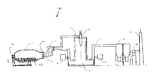
Figures 1-6 show a preferred form of apparatus 100 for decoating organics in
metal
scrap and/or gasifying organic material to generate synthetic gas (syngas),
The
apparatus has a single entry tilting rotary furnace 1 which feeds gases
through passage
means in the form of an exhaust ducting 2 to an oxidising means in the form of
a thermal
oxidizer 31 and then to a separator 9, fan or blower 26 and exhaust means
(chimney) 10.
CA 02687250 2009-11-10
WO 2008/122896 PCT/IB2008/001751
8
The separator 9 is commonly known as a baghouse and is used to separate dust
and
particulates from the gas stream. Hot gases from the thermal oxidizer 31 are
fed back to
the furnace drum 15 by way of passage means in the form of a return ducting 3.
The furnace comprises a refractory lined drum 15 a door 11 and a drive
mechanism 25
that is used to rotate the furnace about its longitudinal axis 104. The
furnace drum has a
tapered portion 13 near the furnace door 11 to permit better gas flow
circulation around
metal and/or organics scrap 14 in the furnace and better control over the
loaded scrap
14 during discharge.
The furnace 1 is mounted for tilting forwards and backwards about a generally
horizontal
pivot axis 102. A hydraulic system 32 is used to tilt the rotary furnace 1
forward, about
the axis 102, during discharge, and slightly backward during charging and
processing of
the material 14 (as shown in Figure 1) to improve the operational
characteristics of the
furnace. .
The furnace door 11 is refractory lined and equipped with an elaborate door
seal
mechanism 12 which allows rotation of the furnace drum 15 relative to the door
11 and
ensures tight closure and complete separation between the rotary furnace
internal
atmosphere 16, and the external atmosphere 30. The furnace door 11 has two
apertures or hole 28, 29. One aperture 28 is sealingly connected to the
exhaust ducting
2 and the second aperture 29 is sealingly connected to the return conduit 3.
Both of
these apertures are designed so as to maintain a robust seal that prevents
atmospheric
air from leaking into the rotary furnace atmosphere 16 during operation.
During the operation the rotary furnace drum 15 is tilted slightly backward as
shown in
Figure 1 and the furnace door 11 is tightly closed. The furnace is rotated by
the drive
mechanism 25. The hot sub-stoichiometry gases are introduced into the furnace
from
the conduit 3 via a high velocity nozzle 18 which protrudes inside the furnace
through the
aperture 29. The nozzle is sealed to the aperture 29. Similarly, the exhaust
ducting 2 is
coupled to the interior of the furnace through the aperture 28 by way of an
inlet 17. Both
the exhaust and return ductings 2, 3 have respective rotating airtight flanges
22, 23
(Figure 4) that permit the door 11 to be opened without stressing the sealing
of the
ducting 2, 3 to the door 11.
CA 02687250 2009-11-10
WO 2008/122896 PCT/IB2008/001751
9
The ducting 2 connects the exhaust gases from the furnace to a thermal
oxidiser 31
where it is burnt in the heat stream from a burner 6 before those burnt gases
are passed
to the baghouse 9.
The thermal oxidizer 31 is a vertical cylindrical shape structure made of
steel and is lined
with a refractory material 5 that can withstand high temperatures of typically
around
24000 F. The hot gases from the furnace 1 contain volatile organic compounds
(VOCs)
and the thermal oxidizer volume is designed so as to ensure that the VOC-
filled gases
are retained in the oxidiser for a minimum of 2 seconds residence time. The
thermal
oxidizer is heated by a multi-fuel burner 6 capable of burning both virgin
fuel (such as
natural gas or diesel) and the VOC from the furnace 1. The ducting 2 for the
VOC gases
is connected directly to the burner 6 and directly supplies the VOC as an
alternative or
additional fuel to the burner.
The gases in the thermal oxidizer 31 have two exit paths. One exit path is
through the
return ducting 3 to provide heating or additional heating to the rotary
furnace 1. The
second exit path is through a further passage means in the form of an exit
ducting 7
towards the baghouse 9.
A gas-conditioning unit 4 is connected in the return ducting 3 and is used to
condition the
gas prior to its reaching the furnace. The conditioning unit 4 adjusts the gas
temperature
via indirect cooling and cleans both the particulates and acids from the gas.
A second
gas-conditioning unit is also provided in the exit ducting 7 and adjusts the
gas
temperature via indirect cooling and cleans both the particulates and acids
from the gas
in a first phase of gas. The exit gases travel from the gas-conditioning unit
8 through the
baghouse 9 and then through an ID fan 26 which assists movement of the gases
along
the ducting 7 and through the baghouse 9. The gases then exhaust via a chimney
10 to
atmosphere.
The return gases passing along the ducting 3 towards the rotary furnace 1 are
sampled
prior to entering the rotary furnace by a sampling means 20 whilst the outlet
gases from
the furnace are sampled by a second sampling means 21 in the outlet ducting 2,
The
two sampling means are sampling systems which generate signals representative
of
various parameters of the gases such as temperature, oxygen content and carbon
monoxide content. These signals are applied to a gas analyzer 19, The gas
analyzer 19
analyses the signals and sends the results to a process control system 106.
CA 02687250 2009-11-10
WO 2008/122896 PCT/IB2008/001751
111
Several sensors 108 are installed inside the rotary furnace 15 and send a
continuous
stream of data to the process control system 106 while the furnace in
operation. These
sensors are conveniently thermocouples that measure parameters such as the
atmospheric temperature, pressure, oxygen content and CO content in the
furnace and
generate signals representative of the parameters. This data is continuously
logged and
the signals sent to the process control system 106 which also receives data
representing
the rotational speed of the furnace and the speed of the gases injected from
the nozzle
18. The process control system can also be programmed with the type of
material to be
processed and adjusts the various operating parameters including the
temperature of the
return gases, oxygen level, return gas velocity and the rotary furnace
rotational speed in
dependence on the programmed values and/or the received signals. To control
the de-
coating finishing time both the return gases entering the rotary furnace and
the gases
exiting the rotary furnace are monitored in a closed circuit by the gas
analyzer 19 which
records both the oxygen level and the CO level. In addition, the control
system 106 can
also control the burner 6 to control the temperature in the oxidiser 31.
The process control system controls the processing cycle the end of the de-
coating cycle
based on the received signals .
The rotary tilting de-coating furnace uses a standard charging machine 24, for
charging
the metal scrap and/or organics into the furnace. During this operation,
rotation of the
furnace 1 is stopped, the door 11 is opened and the furnace is tilted backward
to permit
the scrap to be loaded and pushed toward the far end of the furnace and toward
the
furnace back wall 27. The same procedure is effected during a discharging
operation
except that the furnace is tilted forward to empty the de-coated scrap into
the charging
bin or a separate collection system.
Referring now to Figures 8 and 9, these show a modification to the apparatus
of Figures
1 to 7 with like parts being given like reference numbers.
As can be seen from Figures 8 and 9, the main difference between this
embodiment and
that of Figures 1 to 7 is that the return ducting 3 is omitted.
In all other respects, the apparatus of Figures 8 and 9 operates in a similar
manner to
that of Figures 1 to 7.
CA 02687250 2009-11-10
WO 2008/122896 PCT/IB2008/001751
11
The above described apparatus does not use a burner in the tilting, rotary
furnace, does
not melt the metal scrap and only operates below the melting temperature of
the scrap
metal, typically < 1400 F. The embodiment of Figure 1 uses recycled gases
with the
oxygen content below the stoichiometric level (more specifically < 12% by wt
of oxygen)
to partially combust the organics in the tilting rotary furnace. The gasified
organics
depart the furnace from the flue, in a complete closed circuit where no air is
allowed to
entrain into the flue gases. These organic filled gases (synthetic gases) are
either fully
incinerated in a separate thermal oxidizer, where a stoichiometric burner uses
either
natural gas or liquid fuel to ignite the synthetic gas, or it is partially
oxidised via a burner
and other portions of the synthetic gas are collected and stored for further
use. The
system identifies when the organics are fully gasified, and the metal scrap is
fully clean.
It will be appreciated that any feature of any embodiment may be used in any
other
embodiment.