Note : Les descriptions sont présentées dans la langue officielle dans laquelle elles ont été soumises.
CA 02688081 2009-12-10
EMC-1001
Title: VENT APPARATUS
BACKGROUND
[0001] A "two-way" hingeless vent is typically used in vehicles such as trucks
to
provide additional ventilation and cooling when a door to the vent is open.
Also, when
the door of the vent is closed, the door may seal the vent and prevent a flow
of air and
water into the vehicle through the vent. However, the compression forces used
to
maintain the door in a closed position as the vehicle moves, often makes such
vents
difficult to open. Thus, there exists a need for an improved "two-way"
hingeless vent
that is relatively easier to open and includes other features as will be
apparent from the
following description.
SUMMARY
[0002] The following is a brief summary of the subject matter that is
described in
greater detail herein. This summary is not intended to be limiting as to the
scope of the
claims.
[0003] An example embodiment of a vent apparatus (referred to herein as a
"vent") may include a door that is operative to open in two different
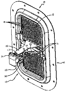
directions, so as to
provide either an inflow of air into a moving vehicle or an outflow of air out
of the
moving vehicle. The vent may include a handle which is connected to a guide
via a lever
assembly. Movement of the handle to a first side of the guide, causes the door
of the vent
to open in a first direction (e.g., providing an inflow of air). Movement of
the handle to a
second opposite side of the guide, causes the door of the vent to open in a
second
1
CA 02688081 2009-12-10
EMC-1001
direction (e.g., providing an outflow of air). Movement of the handle to a
center position
of the guide causes the door of the vent to close and prevent the inflow and
outflow of air
through the vent.
[0004] In an example embodiment, the guide may include a plurality of recesses
(also referred to herein as "detents"). Also the handle may include a movable
bolt that
slides between a retracted and extended position with respect to the handle
into and out of
the detents. In addition, the vent may include a lever assembly. The lever
assembly is
adapted to maintain the handle sufficiently close to the guide (as the handle
moves
relative to the guide to open and close the door) such that the bolt is
operative to slide
along the guide into and out of the detents and move relative to the handle
responsive to
changes in distance between the guide and the handle.
[0005] Other aspects will be appreciated upon reading and understanding the
attached figures and description.
BRIEF DESCRIPTION OF THE DRAWINGS
[0006] Figure 1 is a perspective view of an example embodiment of a vent.
[0007] Figure 2 is a front view showing a door of the vent.
[0008] Figure 3 is a cross-sectional view of the door.
[0009] Figure 4 is a bottom view of the vent with the door closed.
[0010] Figure 5 is a bottom view of the vent with the door open in a first
direction.
[0011] Figure 6 is a bottom view of the vent with the door open in a second
direction.
2
CA 02688081 2009-12-10
EMC-1001
[0012] Figure 7 is a side view showing features of a guide of the vent.
[0013] Figure 8 is a side view showing features of a support bracket of the
guide.
[0014] Figure 9 is a back view showing a handle of the vent.
[0015] Figure 10 is a cross-sectional view showing features of a detent cover
of
the guide.
[0016] Figure 11 is a side view of the handle with the bolt in a retracted
position.
[0017] Figure 12 is a side view of the handle with the bolt in an extended
position.
[0018] Figure 13 is a cross-sectional view of the handle and bolt.
[0019] Figure 14 is a further cross-sectional view of the handle and bolt.
[0020] Figure 15 is a plan view of the handle and lever assembly.
10021] Figure 16 is a perspective view of a vent mounted in a vehicle.
[0022] Figure 17 is a back side view of a vent mounted in combination with a
fan.
[0023] Figure 18 is a back side view of an alternative configuration of a vent
mounted in combination with a fan.
[0024] Figure 19 is a perspective view showing features of an alternative
configuration of a detent cover of the guide.
[0025] Figure 20 is a side view showing features of the alternative detent
cover of
the guide.
[0026] Figure 21 is a side view showing features of an alternative
configuration
of a bolt.
3
CA 02688081 2009-12-10
EMC-1001
DETAILED DESCRIPTION
[0027] Various technologies pertaining to a vent apparatus will now be
described
with reference to the drawings, where like reference numerals represent like
elements
throughout.
[0028] With reference to Figure 1, a back or rear view of an example
embodiment
of a vent apparatus (or "vent") 10 is illustrated. The vent 10 may include a
perforated
screen 12 having an interior face 13 and a corresponding exterior face (not
shown in
Figure 1, but generally indicated as a face 14 located on the opposite side of
the screen
12).
[0029] The screen 12 may correspond to a plate or other structure that
includes a
plurality of perforations 15 (i.e., holes) therethrough. Such perforations may
correspond
to small circular, hexagonal or other shaped holes created in the plate.
However, in
alternative embodiments other forms of screens with perforations therethrough
may be
used. For example, an alternative screen may include a wire mesh, a set of
spaced apart
parallel bars, or any other configuration of a perforated structure that is
operative to
permit airflow through the structure, while preventing the passing of unwanted
objects
(e.g. large bugs, road debris, etc.).
[0030] Figure 2 illustrates a front side view of the vent. Here the vent may
include a door 18 adjacent the exterior face of the screen. Figure 2 shows the
door in a
4
CA 02688081 2009-12-10
EMC-1001
closed position in which the door is located in contact with the screen (or a
frame 70
around the screen) and covers the perforations through the screen.
[00311 As illustrated in Figure 3 (showing the door 18 apart from the vent),
the
door 18 may include a seal 96 such as a foam sheet (or other compressible
material) that
is adhesively mounted to an inside surface of the door. When the door is in
the closed
position (as shown in Figure 2), the door may compress the seal 96 against the
exterior
face of the screen in order to prevent (or at least substantially prevent) the
inflow of air or
water through the screen, and/or to reduce the transmission of road noises,
and other
sounds through the vent.
[0032] In addition, as shown in Figure 3, the door 18 may include two or more
spaced apart arms 20, 22 that extend from the door. Referring back to Figure
1, the two
spaced apart arms 20, 22 extend through at least one slot 16 in the screen.
For example,
the screen may include separate slots 16 (e.g., two) as shown in Figure 1
which
respectively receive the two arms of the door. However, in an alternative
embodiment,
rather than having two spaced apart slots 16 to receive the two arms of the
door, the
screen may include one relatively wider slot that is sized to receive both
arms of the door
therethrough.
[0033] As illustrated in Figure 1, an example embodiment of the vent 10 may
include a handle 26 that is in pivoting connection with the two spaced apart
arms 20, 22.
In addition, an example embodiment of the vent 10 may include a guide 24
mounted
adjacent the interior face of the screen such that at least a portion of the
guide is
positioned between the spaced apart arms 20, 22 of the door that extend
through the at
least one slot 16 in the screen.
CA 02688081 2009-12-10
EMC-1001
[0034] As illustrated in the bottom views of the vent in Figures 4-6, the
handle 26
is operative to move relative to the guide 24 to cause the door 18 to move
between a
closed position 62 (shown in Figure 4) adjacent the screen to one of a
plurality of open
positions 64, 65 (shown in Figures 5 and 6) extending at an acute angle with
respect to
the screen. In example embodiments, the guide 24 has a configuration such that
the door
18 will open in different directions (as depicted in Figures 5 and 6)
depending on which
side of the guide the handle is moved.
[0035] Figure 7 illustrates an example configuration for the guide 24. Here
the
guide 24 may include generally centrally located apex 46. Also, the guide 24
may
include a base 48 adjacent the screen of the vent. In addition, the guide may
include two
opposed first and second sides 50, 52 that extend from the apex to the base.
In this
example embodiment of the guide, the apex has a length 54 that is narrower
than a length
56 of the base. As a result, the overall appearance of the guide may resemble
a triangular
shape.
[0036] In order to mount the guide to the vent adjacent the screen (as
illustrated in
Figure 8), the guide may include a support bracket 74. The support bracket may
have a
sufficient length that it is operative to be mounted to portions of the vent
on either side of
the screen. For example, as shown in Figure 9, the vent may include a frame 70
with an
interior area 72 that includes the screen 12. Here the support bracket 74 of
the guide is
mounted to opposite sides of 76, 77 of the frame in a location that extends
over and
between the slots 16 in the screen.
[0037] As illustrated in Figure 10, the example guide may include a detent
cover
78 that is mounted so as to extend in surrounding relation of portions of the
support
6
CA 02688081 2009-12-10
EMC-1001
bracket 74 (shown in Figure 8). Such a detent cover 78 may correspond to a
plastic
sleeve that slides over top of the support bracket to provide a guide with an
outer guide
surface 34 with a configuration that includes the apex and sides of the guide
described
previously. For example, as shown in Figure 7, the guide surface provided by
the detent
cover may include a plurality of spaced apart recesses (i.e., detents) 36 on
each of the
sides 50, 52 of the guide. The detent cover may also provide a detent on the
apex 46 of
the guide.
[0038] Although in this example embodiment, the guide is shown as being
described as being formed from a support bracket 74 and a detent cover 78, it
is to be
understood that in alternative embodiments the guide may be comprised of a
single part
(e.g. a metal support bracket with an outer surface that corresponds to the
described guide
surface of the detent cover). Also in alternative embodiments, rather than
having a detent
cover in the form of a sleeve that slides over and encases portions of the
support bracket,
the detent may have other configurations that mount to the support bracket.
For example,
as illustrated in Figure 19, a detent cover 350 may be configured as a side
mounted
component with a single side wall 354 that includes projections 352. In this
embodiment,
the guide may be assembled by snapping the detent cover adjacent a side of the
support
bracket, such that the projections 352 extend through corresponding apertures
(not
shown) in the support bracket to hold the guide together.
[0039] Figure 20 shows a side view of the alternative embodiment of the detent
cover 350 shown in Figure 19. Figure 20 also illustrates an alternative
configuration for
the guide surface 356 provided by the detent cover 350. Here the guide surface
includes
a relatively wider upper portion 358 of the guide surface below the apex 360,
compared
7
CA 02688081 2009-12-10
EMC-1001
to the narrower upper portion of the guide surface below the apex 46 of the
detent cover
78 shown in Figure 10.
[0040] In addition, although the support bracket 74 of the guide is described
as
being mounted to a frame that surrounds the screen, it is to be understood
that alternative
embodiments may have other configurations. For example, the support bracket
may be
mounted directly to portions of the screen intermittent of the two slots 16
through the
sleeve. In addition, although the vent has been described as having a frame
surrounding
the screen, it is to be understood that the frame and screen may correspond to
one
common piece of metal (such as steel) that has been stamped to include the
frame portion
surrounding an interior perforated screen portion. Furthermore, in alternative
embodiments the frame and screen may be separate components and/or may be made
of
separate materials which are mounted together using suitable fasteners (e.g.,
via welding,
screws, rivets, or any other mechanism suitable to fasten such parts
together).
[0041] In example embodiments of the vent, the handle may include a movable
portion that moves relative to the handle and is operative to extend into the
previously
described detents in the guide as the handle is moved along the guide. Figure
11
illustrates an example embodiment of the handle 26, in which the movable
portion
corresponds to a movable bolt 28 that is operative to project from the handle.
The bolt is
operative to move relative to the handle in a first direction 74, from a
retracted position
70 (shown in Figure 11) to an extended position 72 (shown in Figure 12). The
bolt is
also operative to move in an opposite second direction 76 from the extended
position to
the retracted position. Figure 13 shows a cross-sectional view of the handle
26 and bolt
28. As shown in this view, the handle may include a biasing member 32 that is
operative
8
CA 02688081 2009-12-10
EMC-1001
to urge the bolt to move in the first direction 74 relative to the handle.
Such a biasing
member may correspond to a coil spring positioned inside the handle between an
interior
wall 42 of the handle and a portion 44 of the bolt.
[0042] Figure 14 illustrates another cross-sectional view of the handle 26
(rotated
90 degrees compared to Figure 13). As shown in this view, the bolt 28 may
include an
aperture 38 therethrough. This aperture of the bolt is elongated in the first
and second
directions to enable the bolt to move in the first and second directions
relative a pin 40
that extends through the handle. Referring back to Figure 1, this pin 40
extends through
the arms 20, 22 of the door as well to place the handle in pivoting connection
with the
arms of the door. The elongated aperture in the bolt enables the bolt to slide
relative to
the handle and the pin 40.
[0043] In addition, it should be appreciated that embodiments of the bolt 28
may
have alternative configurations which may vary for example depending on the
desired
configurations for the handle and the guide surfaces. For example, Figure 21
illustrates
an alternative configuration 400 for the bolt, in which the end of the bolt
includes
concaved sides 402, 404 and a relatively more blunted tip 406 compared to the
bolt 28
shown in Figure 14.
[0044] Referring back to Figure 1, in example embodiments, the handle 26 may
be in operative connection with a lever assembly 30 that extends from the
handle to the
guide and is in pivoting connection with the guide. In this example
embodiment, as the
handle moves relative to the guide to move the door between the closed
position 62
(shown in Figure 4) and the plurality of open positions 66, 68 (shown in
Figures 5 and 6),
the lever assembly 30 is adapted to maintain the handle 26 sufficiently close
to the guide
9
CA 02688081 2009-12-10
EMC-1001
24 such that the bolt is operative to slide against the guide, and move
relative to the
handle responsive to changes in distance between the guide and handle. Thus,
the bolt
will slide into and out of the recesses 36 (e.g., detents) in the guide
surface 34 as the
handle moves in a path along and spaced apart from the guide surface 34.
[0045] As discussed previously, the direction of the opening of the door 18 of
the
vent depends on which side of the guide 24 that the handle is moved. When the
bolt is
positioned to extend in the detent in the apex of the guide (shown in Figure
7), the door is
in the closed position (as shown in Figure 4). In addition, as shown in Figure
5, the
exterior face 14 of the screen includes a first side 58 and an opposed second
side 60.
When the bolt is positioned to extend in a detent on the first side 50 of the
guide, the door
is in one of the plurality of open positions and extends outwardly from the
second side 60
of the screen at an acute angle 66 with respect to the screen. Correspondingly
as shown
in Figure 6, when the bolt is positioned to extend in a detent of the second
side 52 of the
guide, the door is in one of the plurality of open positions and extends
outwardly from the
first side 58 of the screen at an acute angle 68 with respect to the screen
12. In these
example embodiment, when the door is in an open position, an edge of the door
or
interior surface adjacent an edge of the door (e.g. surface 100 shown in
Figure 3) may be
in contact with a portion of the screen and/or frame.
[0046] In addition, it should be noted that the angles 66 and 68 at which the
door
18 opens with respect to the screen, depends on which detent the bolt extends
into along
the sides 50, 52 of the guide. Also, it is to be understood that the
configuration of the
guide surface and other geometries of the vent described herein is only an
example, and
that alterative embodiments may have alternative configurations (e.g.,
different
CA 02688081 2009-12-10
EMC-1001
arrangement of the detents, handle, bolt, screen, door, lever assembly, etc.)
that result in
different angles 66 and 68 for the door with respect to the screen.
[0047] Referring back to Figure 5, an example configuration of the lever
assembly 30 is illustrated. In this example, the lever assembly includes a
first lever 80
and a second lever 82. The first lever may be in rigid connection with the
handle 26 and
extends outwardly from the handle in the first direction 74. The second lever
82 is in
pivoting connection with first lever 80 at a first pivot position 84 on the
first lever that is
spaced apart from the handle 26. In addition, the second lever 82 is in
pivoting
connection with the guide 24 at a second pivot position 86 on the guide that
is spaced
apart from the first pivot position 84 on the second lever 82.
[0048] Figure 15 shows a side view of the level assembly 30. As shown in
Figure
15, the level assembly 30 may include a biasing member such as a spring 88
extending
between the first pivot position 84 and a third pivot position 90 on the guide
34 that is
spaced apart from the second pivot position 86 on the guide. As shown in
Figure 7, the
second pivot position 86 is located on the guide 24 adjacent the apex 46 and
centered
between the first and second sides 50, 52. Also the third pivot position 90
(to which the
spring is mounted) is located between the second pivot position 86 and the
base 48
centered between the first and second sides 50, 52.
[0049] In these example embodiments, a described pivot location corresponds to
the position of the axis at which the described elements pivot with respect to
each other.
Pins, rivets, shafts, screws, bolts, or any other device operative to enable
the elements to
pivot with respect to each other may be used to connect the elements. In
addition, such
devices may be adapted to accommodate the attachment of other elements at the
pivot
11
CA 02688081 2009-12-10
EMC-1001
location. For example, as shown in Figure 15, a shoulder rivet 98 may be used
to provide
a pivoting connection between the first lever 80 and the second lever 82 as
well as
provide a shoulder for an end of the spring 88 to be mounted.
[0050] In example embodiments, the configuration of the lever assembly is
operative to require a sufficient amount of force to initially move the bolt
from the apex
of the guide to a side of the guide (to open the vent door) in order to
provide a default
resistance to movement of the door that enables a tight weather resistant seal
between the
door and screen. However, once the door is opened and the bolt is positioned
along the
sides of the guide, the amount of force necessary to move the door at
different angles (by
sliding between different adjacent detents) is relatively less than the
initial force to open
the door. For example, the lever assembly is adapted to require use of a
greater amount
of force on the handle to move the bolt from (as shown in Figure 7) the recess
on the
apex 46 to the first recess 92 than to move the bolt from the first recess 92
to an adjacent
second recess 94.
[0051] As described herein, the movable portion of the handle has been
referred
to as a bolt. However it is to be understood that the use of the term bolt
does not imply
that this movable portion is a fastener type bolt (e.g., having threads).
Rather, as used
herein the term bolt encompasses any movable element that provides locking
features
with respect to the guide. Such locking features for example, include the
ability of the
bolt (in combination with the spring in the handle) to provide sufficient
resistance to
being moved out of a detent on the guide, so as to prevent wind forces acting
on the door
from moving the door to a different angular position with respect to the
screen. In
12
CA 02688081 2009-12-10
EMC-1001
alternative embodiments other types of combinations of bolts and/or biasing
members
may be used to provide such locking features in the handle.
[0052] As discussed previously, embodiments of the described vent may be
adapted to be mounted in a vehicle. Figure 16 illustrates an example of a
vehicle 200 that
may include the described vent. Here the vehicle may include an exterior wall
202 (such
as wall of the cab of the vehicle). Such a wall may be manufactured and/or
modified to
include an opening 204 in the wall through which the vent 10 may be mounted
with the
door 18 facing an area outside the vehicle. However, it is to be understood
that the
described vent may be used in other types of applications, such as a vent for
a room of a
building, or any other application that requires a vent.
[0053] In addition, alternative embodiments of the described vent may be
combined with other types of cooling elements. For example, as schematically
shown in
Figure 17, an example vent apparatus 300 may include a frame 302 that is
adapted to
have an electric fan 304 mounted adjacent the manually operated vent 10
described
previously. Also for example, as shown in Figure 18, an example vent apparatus
320 may
include a frame 322 that is adapted to have an electric fan 324 mounted to
traverse (i.e.
overlap) portions of the interior face of the screen 12 of the manually
operated vent 10
described previously.
[0054] In the foregoing description, certain terms have been described in
example
embodiments for purposes of brevity, clarity and understanding. However no
unnecessary limitations are to be implied therefrom because such terms are
used for
descriptive purposes and are intended to be broadly construed. Moreover the
descriptions
13
CA 02688081 2009-12-10
EMC-1001
and illustrations herein are by way of examples and the embodiment is not
limited to the
features shown or described.
[0055] Further, in the following claims any feature described as a means for
performing a function shall be construed as encompassing any means known to
those
skilled in the art as being capable of carrying out the recited function, and
shall not be
deemed limited to the particular means shown or described for performing the
recited
function. in the foregoing description, or mere equivalents thereof.
[0056] Additionally, it may be recognized that the examples provided herein
may
be permutated while still falling under the scope of the claims.
14