Note : Les descriptions sont présentées dans la langue officielle dans laquelle elles ont été soumises.
CA 02690149 2009-12-07
WO 2009/123646 PCT/US2008/059471
CANDLE BURNING DEVICE
FIELD OF THE INVENTION
[001] The present specification describes a candle burning device, for
example, a candle
follower. The candle follower is particularly useful for candles having a
wider diameter which
tend to burn unevenly and/or incompletely. Also described is a removable
candle follower that,
due to its relatively slim profile, allows for the use of nearly the entire
candle, and
simultaneously functions as an aesthetically pleasing decoration.
BACKGROUND
[002] The problems associated with dripping candles, complete burning and
even
burning are well recognized. In particular, the problems associated with
burning wider candles,
for example, candles having a relatively large diameter (i.e., greater than
about an inch (about 2.5
cm)) are readily apparent. For example, these types of candles typically burn
unevenly or core
burns deeply leaving the walls intact or a combination thereof The end result
is that much of the
candle goes unused and the aesthetic appeal of the candle is ruined.
[003] There have been numerous attempts to design candle burning devices,
for
example, candle followers that sought to provide practical and aesthetically
attractive solutions.
However, currently available candle followers suffer from a variety of
shortcomings. For
example, candle holders currently on the market are bulky and/or of relatively
heavy
construction, and are designed to sit only on the shoulders or outer edges of
the candle. These
designs can tend to cause the candle to burn unevenly. Other undesirable
features include the
tendency to fit like a skirt or sleeve over the outside of the candle, which
not only conceals the
candle but also prevents complete burning. Such followers are also undesirable
because they are
constructed from expensive glass, solid metals or ceramics. Besides being
costly to manufacture
and buy, these materials can be become too hot and cause tilting or cocking as
the candle burns
unevenly. Even less desirable is that many currently available candle
followers cause wax
pooling along the top and outside of the candle, which inevitably leads to
considerable dripping
and mess.
CA 02690149 2012-08-14
12016-9
[004] Thus, there exists a need in the market for a candle burning device,
for example,
a candle follower, that is simple, light, reusable, inexpensive to manufacture
and sell, and that
allows for the substantially even burning of the candle, and at the same time
reduces dripping
and waste. Moreover, there is a need for such a device that is aesthetically
pleasing and which
does not conceal a significant portion of the candle. Furthermore, there is a
need for a device
which provides all these advantages and, in addition, allows the user to bum
nearly the entire
candle.
SUMMARY
[005] Described herein is a device for the improved burning of a candle. In
particular,
the invention relates to a candle follower that addresses one or more of the
well known
shortcomings in the art. In certain aspects the invention encompasses a candle
burning device
comprising a substantially planar body defining an outer rim, a plurality of
vent openings, and an
approximately centralized depressed recess, the recess having an aperture for
receiving a wick
from a candle; and wherein the device is formed of a heat conducting material.
[005a] According to another aspect, the present invention provides a
candle burning
device comprising: a substantially planar body having a top and bottom
surface, wherein the
body defines an outer rim, an approximately centralized depressed recess with
respect to the top
surface defining, an aperture for receiving a wick from a candle, a plurality
of upwardly biased
fins near the wick aperture, wherein the device is formed of a unitary piece
of heat conducting
material to conduct heat from the device to a top surface of a candle, and
wherein all the fins are
upwardly biased.
[005b] According to yet another aspect, the present invention provides a
candle burning
device comprising: a substantially planar body having a top and bottom
surface, wherein the
body defines an outer rim, an approximately centralized depressed recess with
respect to the top
surface defining, an aperture for receiving a wick from a candle, a plurality
of upwardly biased
fins near the wick aperture, wherein the device is formed of a unitary piece
of heat conducting
material to conduct heat from the device to a top surface of a candle, and
wherein all the fins are
upwardly biased; and a flange extending approximately perpendicularly from the
outer rim,
wherein the flange is adapted to fit over the outer edge of a candle, and the
planar body also
defines a plurality of vent openings.
2
CA 02690149 2012-08-14
12016-9
[005c] According to still another aspect, the present invention provides a
candle burning
device comprising a substantially planar body defining an outer rim, an
approximately
centralized depressed recess having an aperture for receiving a wick from a
candle, and a
plurality of upwardly biased fins near the wick aperture. The device is formed
of a heat
conducting material.
[006] Other aspects and advantages of the present invention will become
readily
apparent in view of the following Detailed Description and the accompanying
Drawings.
BRIEF DESCRIPTION OF THE DRAWINGS
[007] The accompanying drawings, which are incorporated into and form a
part of the
specification, illustrate several embodiments of the present invention and,
together with the
description, serve to explain the principles of the invention. The drawings
are only for the
purpose of illustrating a preferred embodiment of the invention and are not to
be construed as
limiting the invention.
[008] FIG. 1 illustrates a top perspective view of an embodiment of the
present
invention;
[009] FIG. 2 illustrates the functioning of a device encompassed by the
claims.
(A) illustrates the common problem of uneven/incomplete candle burning
observed with candles
of larger diameter or width (e.g. greater than approximately one inch (about
2.5 cm));
(B) illustrates the results observed with burning an identical candle with the
device of the
invention.
2a
CA 02690149 2009-12-07
WO 2009/123646 PCT/US2008/059471
The candle follower of the invention allows for approximately even and
complete burning of the
candle.
[0010] FIG. 3 illustrates the functioning of another device encompassed
by the claims.
In this embodiment the candle follower of the invention comprises multiple
apertures to
accommodate candles having more than one wick.
[0011] FIG. 4 illustrates a top perspective view of another embodiment of
the present
invention. This embodiment further comprises at least one upwardly biased fin
portion disposed
proximally to the wick aperture to substantially shield the candle flame from
being extinguished
by air currents. In addition, the fin portions allow for more efficient heat
capture and
conductance.
[0012] FIG. 5 illustrates a top perspective view of another embodiment of
the present
invention.
[0013] FIG. 6 illustrates a top perspective view of another embodiment of
the present
invention.
[0014] As indicated above, the drawings are provided for exemplary
purposes only and
are not to be construed as limiting. For example, as would be understood by
those of skill in the
art, any of the features depicted in the drawings can be combined with any
other embodiment or
embodiments in any conceivable combination, all of which are contemplated by
the inventors
and encompassed by the present claims.
DETAILED DESCRIPTION
[0015] Described herein is a candle burning device, for example, a candle
follower,
which addresses many of the well known shortcomings of the art. The candle
follower described
and claimed herein is particularly useful for candles having a wider diameter,
which tend to burn
unevenly and/or incompletely. In certain embodiments, the candle follower
described herein is
formed of a relatively light, heat-conducting material, is simple and
economical to manufacture
and sell but is also durable and reusable. In additional embodiments, the
candle burning device
of the invention is relatively slim in its profile, and designed to fit over
the apical or top portion
or surface of a candle, which allows for the use of nearly the entire candle,
and simultaneously
functions as an aesthetically pleasing decoration.
3
CA 02690149 2009-12-07
WO 2009/123646 PCT/US2008/059471
[0016] As used herein, "relatively slim" means about 3 inches or less in
height with
reference to the vertical plane (See Figure 1, "c"). In certain preferred
embodiments the device
of the invention is equal to or less than about 3, 2, 1, 0.5, or 0.25 inches
in height. In a preferred
embodiment, the device is from about 1116th of an inch to about 1 inch in
height (for conversion
and reference purposes, an 1 inch is approximately 2.5 cm).
[0017] In certain aspects, the candle burning device comprises a
substantially planar
body defining an outer rim, a plurality of vent openings, and an approximately
centralized
depressed recess, the recess defining an aperture for receiving a candle wick;
and a flange
extending downward from the outer rim of the body portion, wherein the device
is formed of a
material capable of conducting heat.
[0018] It is expressly contemplated that the device can be manufactured
from any
material capable of conducting heat known to those of skill in the art and the
invention is not
limited in this regard. Exemplary materials suitable for use in the invention
include a metal, for
example, tin, aluminum, steel, nickel, pewter, bronze, copper, gold, silver,
platinum, titanium,
and combinations thereof; alloys; glass; ceramic; and cermet. However, it is
also contemplated
that the heat conducting material used to manufacture the device be in the
form of a sheet or thin
layer; the thin construction reducing the overall weight of the device. The
particular thickness of
which will vary upon a number of considerations such as desired durability,
rigidity, cost, and
ease of manufacture. These factors are readily determined by those of skill in
the art using
routine procedures and methods, and does not require undue experimentation.
[0019] Exemplary embodiments of the instant invention are described in
additional detail
below (with reference to Figs. 1-6), like numbers being used to refer to like
features.
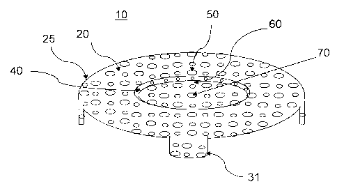
[0020] Figures 1-6 show exemplary candle burning devices 10 of the
invention. The
device 10 comprises a substantially planar body 20 defining an outer rim 25.
The diameter of the
outer rim is depicted by reference arrow, a. It is important to note that the
device may be of any
suitable size, and therefore, a, can be any value measured using any standard
unit or metric, for
example, inches or centimeters. It should also be noted that while the
embodiments depicted in
the Figures are approximately disc-shaped, the invention is not limited
thereto. It is expressly
contemplated that the device of the invention can be of any suitable geometric
configuration
known in the art subject only to the caveat that the particular shape of the
device of the invention
4
CA 02690149 2009-12-07
WO 2009/123646 PCT/US2008/059471
substantially match the cross-sectional geometry of the candle on which it is
to be placed.
However, most candles have a substantially circular cross-section, and
therefore, in certain
exemplary embodiments, the planar body 20 of the device is approximately disc-
shaped.
[0021] The device 10 further comprises an approximately centralized
depressed recess
60. With reference to the exemplary embodiment in Figure 1, the recess defines
a diameter
indicated by reference arrow, "b." Similar to "a" the recess can be of any
size or shape.
However, it is recognized that is the usual situation a flame will burn the
wax in a circular
pattern radiating outward in all directions from the wick, and therefore, in a
preferred
embodiment the recess is circular in shape will be approximately the same size
as the average
size of the pool of molten wax formed by the particular candle. The
determination of the average
size of the pool of molten wax for any particular candle size is readily and
easily determined by
those of skill in the art and does not require undue experimentation. In
addition, the recess 60 of
the device 10 depicted in the Figures also shows a flange 40 extending axially
downward,
substantially perpendicularly from the inner rim of the planar body 20.
However, the invention
is not limited thereto. For example, it is also contemplated that the device
have a recess 60
formed as a gradual or curved depression, for example, a bowl shape, versus
the substantially
vertical wall or flange 40 as depicted in the Figures.
[0022] The recess 60 of the device 10 in the Figures further comprises
and aperture 70
for receiving the candle wick. In certain embodiments, the aperture for
receiving a candle wick
is disposed in approximately the center of the recess. However, the device of
the invention is not
so limited. For example, it is expressly contemplated that the candle burning
device of the
invention can be modified to fit a candle having a plurality of candle wicks,
disposed in any
configuration. Therefore, the candle burning device of the invention may
similarly have a
plurality of apertures for receiving a plurality of candle wicks; the
apertures being arranged in
any suitable configuration.
[0023] Without being bound by any particular theory it is believed that
the recess is
important for the functioning of the device because it allows air to feed the
flame, helps to
regulate the temperature of the device, serves as a seat on the molten wax
allowing the device to
remain balanced, and/or promotes the flow of wax from the periphery to the
molten center.
CA 02690149 2009-12-07
WO 2009/123646 PCT/US2008/059471
[0024] In any of the embodiments described herein, the device may also
comprise one or
more fins 80 (See Figure 4). The fins 80 may be of any suitable size or shape
and provide the
additional advantages of protecting the flame from strong air currents as well
as providing for
more efficient heat conduction.
[0025] In certain embodiments, the candle burning device 10 further
comprises a flange
30 extending downward from the outer rim 25 of the substantially planar body
20. In the
preferred working mode, the flange 30 forms an overhang that is on or near the
side of the candle
body. The flange 30 helps balance the device, promotes even burning of the
candle, and keeps
the device is position atop the burning candle. Also, in certain embodiments,
the length of the
flange 30 is approximately equal to the height of the device 10, as depicted
by reference arrow, c,
described above (See Figure 1). However, the invention is not so limited. For
example,
additional embodiments are contemplated in which the flange 30 has a length
which is larger or
smaller than the height, c, of the device. In addition, the flange 30 can
completely surround the
outer rim 25 as in Figures 1, 4-5 or the flange 30 can be discontinuous, for
example, such as the
tabs 31 of Figure 6.
[0026] In addition, the candle burning device 10 depicted in the Figures
comprises a
plurality of vents 50. The vents may be of any desirable size, shape or
number, and
combinations thereof In addition, in certain embodiments the plurality of
vents 50 are located
only on the planar body 20. In additional embodiments, the vents are disposed
on at least one of
the planar body, the recess portion, the flange or a combination thereof.
[0027] Figures 2 and 3 illustrate the operation and advantages of the
candle burning
device encompassed by the claims. As described above, candles having a
relatively wide
diameter tend to burn unevenly and incompletely (Fig. 2, A). This is a problem
well known in
the art and is recognized as reducing the aesthetic appearance of the candle
as well as resulting in
a significant amount unused or wasted candle. This, of course, means that
consumers do not
usually get their money's worth in terms of enjoyment time, out of the candle.
The present
invention addresses this problem because it provides a simple, durable,
relatively light weight,
and inexpensive candle burning device. As depicted in Figures 2, B; and Figure
3, the present
invention sits atop the candle, and covers substantially the entire apical
surface of the candle. In
normal operating mode, the device of the invention allows the candle to burn
and promotes the
6
CA 02690149 2009-12-07
WO 2009/123646 PCT/US2008/059471
formation of a substantially uniform pool of molten wax in the center. Because
the device is
formed of a thin, heat conducting material, heat is captured from the candle
flame and warms
approximately the entire surface of the device. The device descends by gravity
as the candle
burns. While not being bound by any particular theory, the inventors believe
that the vents help
regulate the temperature of the device surfaces and allow for the formation of
a semi-solid wax
seal between the candle and the device, which promotes the controlled flow of
wax from the
outer portions of the candle into the molten center where it is burned. It is
believed that
overheating of the follower increases the melting rate of the wax, which tends
to result in tilting
of candle follower and uneven burning of the candle.
[0028] Again, while not being limited by any particular theory, the
inventor hypothesizes
that because of the light construction and slim profile, the device of the
invention is able to rest
gently on the molten and semi-solid wax and remain balanced. As such, the
device allows for
the even burning of the candle and resists the tendency to tilt or cock as it
burns (See, Figure 2,
B; and Figure 3). In addition, in contrast to currently available followers
the device of the
invention rests upon the apical or top portion of the candle, and therefore,
the device of the
invention does not conceal the candle or diminish its aesthetic appearance.
Moreover, because
the device sits upon the top surface of the candle it allows the user to burn
nearly the entire
candle. Another advantage of the present invention is that the design promotes
the flow of wax
into the molten center versus prior devices that sit mainly on the outside of
the candle which
tends to promote wax dripping down the sides of the candle body.
[0029] As may be recognized by those of ordinary skill in the pertinent
art based on the
teachings herein, numerous changes and modifications may be made to the above-
described and
other embodiments of the present invention without departing from the scope of
the invention as
defined in the appended claims. For example, the candle follower may take on
any of numerous
different configurations, sizes, colors, or may be formed of any of numerous
different heat-
conducting materials that are currently known or that later become known; any
of a variety of the
disclosed components may be eliminated, or additional components or features
may be added.
For example, the number, shape, and location of vents on the device can be
changed in an almost
innumerable number of ways which are contemplated by the inventors and
encompassed by the
claims. Accordingly, this detailed description of the currently-preferred
embodiments is to be
taken in an illustrative, as opposed to a limiting sense.
7