Sélection de la langue

Search

Sommaire du brevet 2690728 

Énoncé de désistement de responsabilité concernant l'information provenant de tiers

Une partie des informations de ce site Web a été fournie par des sources externes. Le gouvernement du Canada n'assume aucune responsabilité concernant la précision, l'actualité ou la fiabilité des informations fournies par les sources externes. Les utilisateurs qui désirent employer cette information devraient consulter directement la source des informations. Le contenu fourni par les sources externes n'est pas assujetti aux exigences sur les langues officielles, la protection des renseignements personnels et l'accessibilité.

Disponibilité de l'Abrégé et des Revendications

L'apparition de différences dans le texte et l'image des Revendications et de l'Abrégé dépend du moment auquel le document est publié. Les textes des Revendications et de l'Abrégé sont affichés :

  • lorsque la demande peut être examinée par le public;
  • lorsque le brevet est émis (délivrance).
(12) Brevet: (11) CA 2690728
(54) Titre français: EPISSURE MECANIQUE
(54) Titre anglais: MECHANICAL SPLICE
Statut: Accordé et délivré
Données bibliographiques
(51) Classification internationale des brevets (CIB):
  • G02B 6/255 (2006.01)
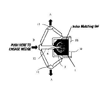
(72) Inventeurs :
  • DOBBINS, PATRICK E. (Etats-Unis d'Amérique)
(73) Titulaires :
  • AFL TELECOMMUNICATIONS LLC
(71) Demandeurs :
  • AFL TELECOMMUNICATIONS LLC (Etats-Unis d'Amérique)
(74) Agent: SMART & BIGGAR LP
(74) Co-agent:
(45) Délivré: 2018-01-02
(86) Date de dépôt PCT: 2008-10-06
(87) Mise à la disponibilité du public: 2009-04-09
Requête d'examen: 2013-09-27
Licence disponible: S.O.
Cédé au domaine public: S.O.
(25) Langue des documents déposés: Anglais

Traité de coopération en matière de brevets (PCT): Oui
(86) Numéro de la demande PCT: PCT/US2008/078898
(87) Numéro de publication internationale PCT: WO 2009046402
(85) Entrée nationale: 2009-12-11

(30) Données de priorité de la demande:
Numéro de la demande Pays / territoire Date
60/977,983 (Etats-Unis d'Amérique) 2007-10-05

Abrégés

Abrégé français

La présente invention concerne un appareil d'épissure mécanique qui comprend une épissure mécanique dotée d'une rainure et d'un composant d'alignement avec un coin. Lorsque le coin est mis en prise dans la rainure de l'épissure mécanique, une ouverture est formée dans l'épissure mécanique et lorsque le coin est retiré de la rainure, l'ouverture se ferme.


Abrégé anglais


A mechanical splice apparatus including a mechanical splice with a groove and
an aligning component with a wedge.
When the wedge is engaged in the groove of the mechanical splice an opening is
formed in the mechanical splice and when the wedge
is disengaged from the groove, the opening closes.

Revendications

Note : Les revendications sont présentées dans la langue officielle dans laquelle elles ont été soumises.


WHAT IS CLAIMED IS:
1. A mechanical splice apparatus, comprising:
a mechanical splice with a plurality of grooves, wherein the mechanical splice
receives a first optical fiber through a first end of the mechanical splice,
where the first
optical fiber resides in a first portion of the mechanical splice, and the
mechanical splice
receives a second optical fiber through a second end of the mechanical splice,
where the
second optical fiber resides in a second portion of the mechanical splice;
a first aligning component with a first wedge, wherein, when the first wedge
is
engaged in a first groove of the plurality of grooves of the mechanical
splice, a first opening
is formed in the first portion of the mechanical splice, and, when the first
wedge is
disengaged from the first groove, the first opening closes; and
a second aligning component with a second wedge, wherein, when the second
wedge
is engaged in a second groove of the plurality of grooves of the mechanical
splice, a second
opening is formed in the second portion of the mechanical splice, and, when
the second
wedge is disengaged from the second groove, the second opening closes.
2. The mechanical splice apparatus according to claim 1,
wherein the first aligning component further comprises at least one additional
first
wedge, and
wherein, when the plurality of first wedges are engaged in the grooves of the
mechanical splice, first openings are formed in the first portion of the
mechanical splice; and,
when the plurality of first wedges are disengaged from the grooves, the first
openings close,
wherein the second aligning component further comprises at least one
additional
second wedge, and
wherein, when the plurality of second wedges are engaged in the grooves of the
mechanical splice, second openings are formed in the second portion of the
mechanical
-7-

splice; and, when the plurality of second wedges are disengaged from the
grooves, the second
openings close.
3. The mechanical splice apparatus according to claim 1, wherein the first
aligning
component comprises a plurality of structures that, when forces are asserted
on the structures,
the first wedge disengages from the first groove, and
wherein the second aligning component comprises a plurality of structures
that, when
forces are asserted on the structures, the second wedge disengages from the
second groove.
4. The mechanical splice apparatus according to claim 1, wherein the first
aligning
component comprises a structure that, when a force is asserted on the
structure, the first
wedge engages in the first groove, and
wherein the second aligning component comprises a structure that, when a force
is
asserted on the structure, the second wedge engages in the second groove.
5. The mechanical splice apparatus according to claim 1, wherein end faces
of the first
and the second optical fibers meet at a middle portion of the mechanical
splice, and the first
portion extends from the first end to the middle portion and the second
portion extends from
the second end to the middle portion.
6. The mechanical splice apparatus according to claim 5, wherein the first
aligning
component opens and closes the entire first portion, and the second aligning
component
opens and closes the entire second portion.
-8-

Description

Note : Les descriptions sont présentées dans la langue officielle dans laquelle elles ont été soumises.

CA 02690728 2015-10-16
MECHANICAL SPLICE
BACKGROUND OF THE INVENTION
1. Field of the Invention
[02] Apparatuses consistent with the present invention relate to mechanical
splices. More
particularly, the present invention relates to mechanical splicing optical
fibers that includes a
component for aligning and the fibers that are being spliced.
2. Description of the Related Art
[03] In order to join fibers from multiple cable reels, the optical fiber
must be either fusion
spliced or mechanically spliced to align the fiber cores prior to joining the
ends to allow
optical energy to past from one fiber to the next. Depending on the quality of
the alignment
there is loss associated with such fiber joints.
[04] In using fusion splicing there is a high cost of the equipment,
special skill levels of the
technician and precision equipment required to prepare the fiber to make this
joint. In
mechanical splicing of optical fibers, there are high losses and special
apparatuses or tools
required to precisely align the optical cores of the fiber. All existing fiber
optic mechanical
splices use some type of special tool or apparatus to assemble the mechanical
splice and
precisely align the optical core of the fiber. These special tools are an
additional cost and add
an element of additional complexity in order to facilitate making a low loss
mechanical splice
joint between optical fibers.
-1-

CA 02690728 2009-12-11
WO 2009/046402 PCT/US2008/078898
[05] The fibers are first prepared by having their protective coating
removed, the fiber
cleaned in pure alcohol and the end faced cleaved to provide a flat endface.
This is the same
process for all splicing, either fusion or mechanical. The special tools
required for mechanical
splicing are to open the elastomer that precisely aligns the fiber cores by a
precision V-groove in
the elastomer. Once both fibers are aligned the tool closes the V-groove and
the fibers are held
in place and in alignment by the closed elastomer. The problem that need to be
addressed is that
these special tools are costly, cumbersome, and need to be replaced and
repaired.
[06] It is an object of this invention to provide a mechanical splice that
is pre-equipped
with a component that can open and close the elastomer, thus eliminating the
need for a special
tool to complete the splice.
SUMMARY OF THE INVENTION
[07] Exemplary embodiments of the present invention address at least the
above
problems and/or disadvantages and other disadvantages not described above.
Also, the present
invention is not required to overcome the disadvantages described above, and
an exemplary
embodiment of the present invention may not overcome any of the problems
described above.
[08] According to an aspect of the present invention, there is provided a
mechanical
splice apparatus, including a mechanical splice with a groove; and an aligning
component with a
wedge; wherein when the wedge is engaged in the groove of the mechanical
splice an opening is
formed in the mechanical splice and when the wedge is disengaged from the
groove, the opening
closes.
[09] According to another aspect of the present invention, there is
provided a
mechanical splice apparatus wherein the mechanical splice includes a plurality
of grooves;
wherein the aligning component includes a plurality of wedges and wherein when
the wedges are
-2-

CA 02690728 2009-12-11
WO 2009/046402 PCT/US2008/078898
engaged in the grooves of the mechanical splice openings are formed in the
mechanical splice
and when the wedge is disengaged from the grooves, the openings close.
[10] According to another aspect of the present invention, there is
provided a
mechanical splice apparatus that also includes a second aligning component.
[11] According to another aspect of the present invention, there is
provided a
mechanical splice apparatus wherein the aligning component includes a
plurality of structures
that, when forces are asserted on the structures, the wedge disengages from
the groove.
[12] According to another aspect of the present invention, there is
provided a
mechanical splice apparatus wherein the aligning component includes a
structure that, when a
forces is asserted on the structure, the wedge engages in the groove.
BRIEF DESCRIPTION OF THE DRAWINGS
[13] These and/or other aspects of the present invention will become
apparent and
more readily appreciated from the following description of the exemplary
embodiments, taken in
conjunction with the accompanying drawings, in which:
[14] Fig. 1 is a perspective view illustrating an exemplary embodiment of
an
unassembled mechanical splice;
[15] Fig. 2 is a perspective view illustrating an exemplary embodiment of
an
assembled mechanical splice;
[16] Fig. 3 is a cross sectional view illustrating an exemplary embodiment
of the
mechanical splice;
[17] Figs. 4 and 5 are cross sectional views illustrating the operation of
an exemplary
embodiment of the mechanical splice.
-3-

CA 02690728 2009-12-11
WO 2009/046402 PCT/US2008/078898
DETAILED DESCRIPTION OF THE INVENTION
[18] In the following description, same drawing reference numerals are used
for the
same elements even in different drawings. The matters defined in the
description, such as
detailed construction and element descriptions, are provided to assist in a
comprehensive
understanding of the invention. Also, well-known functions or constructions
are not described in
detail since they would obscure the invention in unnecessary detail.
[19] Fig. 1 is a perspective view illustrating an exemplary embodiment of
an
unassembled mechanical splice. As illustrated in Fig. 1, the apparatus
includes a mechanical
splice 1 and two aligning components 2, 3 that are used in the splicing
process. The mechanical
splice 1 contains two holes 10, on either end (the second hole is not shown),
where the fibers to
be spliced are inserted. Four grooves 6, 7, 8, 9, are on the top of the
mechanical splice 1. The
grooves extend past the center point 30 of the elastomer when the fiber will
reside (see figure 4).
Although this embodiment has four grooves. The mechanical splice could have
fewer (at least
two) or more grooves.
[20] The aligning components 2, 3 include a portion 5 that holds the
mechanical splice
1. The mechanical splice 1 can be held for example, by a clip 5A, a piece that
5B that covers the
entire bottom of the mechanical splice 1 (as shown in Fig. 4), or by other
suitable means. The
aligning components 2, 3 also include wedges 4, that can be inserted into the
grooves 6, 7, 8, 9.
The wedges do not need to be shaped like a wedge. Any other suitable shape
that can be inserted
into the grooves and force open a channel or hole for the fiber to be inserted
would be
acceptable. The wedges 4 are attached to the aligning splices 2, 3, by
supports 12. The supports
12 can be integrally formed with the wedges 4.
[21] The aligning splices 2, 3, also include structures or "wings" 11,
which are used to
remove the wedges 4 from the grooves 6, 7, 8, 9.
-4-

CA 02690728 2009-12-11
WO 2009/046402 PCT/US2008/078898
[22] Next, the assembly of the mechanical splice will be described. The
aligning
components 2, 3 are either pushed over the mechanical splice 1 and held
together by the clips 5A
(see Figs. 1 and 2), or the mechanical splice 1 is slid through the aligning
components 2, 3 (see
Fig. 5). At this point, the wedges 4 are not inserted into the grooves 6, 7,
8, 9. Next, after
aligning the wedges 4 over the grooves 6, 7, 8, 9, the wedges 4 are inserted
into the grooves by
using a force B (see Fig. 4). The "wings" 11 move out in direction A. The
wedges 4 remain
engaged in the grooves by for example, friction force, or by clips or other
means (not shown).
When the wedges are engaged, the elastomer is forced open to create an opening
such that an
optical fiber can be inserted into the opening in the mechanical splice. For
example, Fig. 4
shows slight opening around the center point 30, where the fiber will reside.
The mechanical
splice 20 can now be used to splice two fibers.
[23] Next, the slicing operation will be described. The fibers are first
prepared by
having their protective coating removed, the fiber cleaned in pure alcohol and
the end faced
cleaved to provide a flat endface. The fibers are inserted into holes 10 of
the mechanical splice 1
until the two endfaces meet at approximately the middle of the mechanical
splice 1. Next, the
wedges of one of the aligning components 2 or 3 are removed from the grooves.
This is done by
applying a force C on the "wings" 11 (see Fig. 5). This causes the support 12,
along with the
wedges 4 to move in direction D. After the wedges 4 are removed from the
grooves, the opening
in the elastomer closes and the elastomer firmly holds the optical fiber in
place. Next, care is
take to make sure that the other fiber is still in contact with the firmly
held fiber, and the wedges
of the second aligning component are removed in the same matter. Finally, both
aligning
components 2, 3 are removed from the mechanical splice 1 and can be discarded.
-5-

CA 02690728 2015-10-16
[24] One advantage of this invention is that the mechanical splice comes
pre-equipped
with the tool required to open and close the elastomer and these are
disposable after the splice
is completed. A great advantage is that the cost of the new technology is
considerably lower
and a special tool is no longer required to assemble the splice.
[25] The scope of the claims should not be limited by the preferred
embodiments set forth
in the examples, but should be given the broadest interpretation consistent
with the
description as a whole.
-6-

Dessin représentatif
Une figure unique qui représente un dessin illustrant l'invention.
États administratifs

2024-08-01 : Dans le cadre de la transition vers les Brevets de nouvelle génération (BNG), la base de données sur les brevets canadiens (BDBC) contient désormais un Historique d'événement plus détaillé, qui reproduit le Journal des événements de notre nouvelle solution interne.

Veuillez noter que les événements débutant par « Inactive : » se réfèrent à des événements qui ne sont plus utilisés dans notre nouvelle solution interne.

Pour une meilleure compréhension de l'état de la demande ou brevet qui figure sur cette page, la rubrique Mise en garde , et les descriptions de Brevet , Historique d'événement , Taxes périodiques et Historique des paiements devraient être consultées.

Historique d'événement

Description Date
Paiement d'une taxe pour le maintien en état jugé conforme 2024-09-27
Requête visant le maintien en état reçue 2024-09-27
Représentant commun nommé 2019-10-30
Requête pour le changement d'adresse ou de mode de correspondance reçue 2018-01-12
Accordé par délivrance 2018-01-02
Inactive : Page couverture publiée 2018-01-01
Inactive : Taxe finale reçue 2017-11-14
Préoctroi 2017-11-14
Lettre envoyée 2017-06-01
Un avis d'acceptation est envoyé 2017-06-01
Inactive : Approuvée aux fins d'acceptation (AFA) 2017-05-24
Inactive : Q2 réussi 2017-05-24
Modification reçue - modification volontaire 2016-12-01
Inactive : Dem. de l'examinateur par.30(2) Règles 2016-06-01
Inactive : Rapport - Aucun CQ 2016-06-01
Modification reçue - modification volontaire 2015-10-16
Inactive : Dem. de l'examinateur par.30(2) Règles 2015-04-16
Inactive : Rapport - Aucun CQ 2015-04-15
Lettre envoyée 2013-10-07
Requête d'examen reçue 2013-09-27
Toutes les exigences pour l'examen - jugée conforme 2013-09-27
Exigences pour une requête d'examen - jugée conforme 2013-09-27
Inactive : Déclaration des droits - PCT 2010-03-11
Inactive : CIB en 1re position 2010-03-10
Inactive : CIB enlevée 2010-03-10
Inactive : CIB attribuée 2010-03-10
Inactive : Page couverture publiée 2010-02-24
Demande reçue - PCT 2010-02-22
Inactive : CIB en 1re position 2010-02-22
Inactive : CIB attribuée 2010-02-22
Inactive : Notice - Entrée phase nat. - Pas de RE 2010-02-22
Inactive : Lettre de courtoisie - PCT 2010-02-22
Exigences pour l'entrée dans la phase nationale - jugée conforme 2009-12-11
Demande publiée (accessible au public) 2009-04-09

Historique d'abandonnement

Il n'y a pas d'historique d'abandonnement

Taxes périodiques

Le dernier paiement a été reçu le 2017-09-20

Avis : Si le paiement en totalité n'a pas été reçu au plus tard à la date indiquée, une taxe supplémentaire peut être imposée, soit une des taxes suivantes :

  • taxe de rétablissement ;
  • taxe pour paiement en souffrance ; ou
  • taxe additionnelle pour le renversement d'une péremption réputée.

Veuillez vous référer à la page web des taxes sur les brevets de l'OPIC pour voir tous les montants actuels des taxes.

Titulaires au dossier

Les titulaires actuels et antérieures au dossier sont affichés en ordre alphabétique.

Titulaires actuels au dossier
AFL TELECOMMUNICATIONS LLC
Titulaires antérieures au dossier
PATRICK E. DOBBINS
Les propriétaires antérieurs qui ne figurent pas dans la liste des « Propriétaires au dossier » apparaîtront dans d'autres documents au dossier.
Documents

Pour visionner les fichiers sélectionnés, entrer le code reCAPTCHA :


Pour visualiser une image, cliquer sur un lien dans la colonne description du document. Pour télécharger l'image (les images), cliquer l'une ou plusieurs cases à cocher dans la première colonne et ensuite cliquer sur le bouton "Télécharger sélection en format PDF (archive Zip)" ou le bouton "Télécharger sélection (en un fichier PDF fusionné)".

Liste des documents de brevet publiés et non publiés sur la BDBC .

Si vous avez des difficultés à accéder au contenu, veuillez communiquer avec le Centre de services à la clientèle au 1-866-997-1936, ou envoyer un courriel au Centre de service à la clientèle de l'OPIC.


Description du
Document 
Date
(aaaa-mm-jj) 
Nombre de pages   Taille de l'image (Ko) 
Page couverture 2017-12-13 1 41
Description 2009-12-11 6 250
Dessin représentatif 2009-12-11 1 20
Dessins 2009-12-11 4 117
Abrégé 2009-12-11 2 66
Revendications 2009-12-11 1 34
Page couverture 2010-02-24 1 46
Revendications 2015-10-16 2 66
Description 2015-10-16 6 229
Revendications 2016-12-01 2 68
Dessin représentatif 2017-12-13 1 13
Confirmation de soumission électronique 2024-09-27 2 69
Avis d'entree dans la phase nationale 2010-02-22 1 195
Rappel de taxe de maintien due 2010-06-08 1 116
Rappel - requête d'examen 2013-06-10 1 118
Accusé de réception de la requête d'examen 2013-10-07 1 189
Avis du commissaire - Demande jugée acceptable 2017-06-01 1 163
PCT 2009-12-11 1 46
Correspondance 2010-02-22 1 18
Correspondance 2010-03-11 2 48
Taxes 2010-09-20 1 38
Modification / réponse à un rapport 2015-10-16 10 303
Demande de l'examinateur 2016-06-01 3 206
Modification / réponse à un rapport 2016-12-01 6 184
Taxe finale 2017-11-14 1 45