Note : Les descriptions sont présentées dans la langue officielle dans laquelle elles ont été soumises.
CA 02691464 2010-02-01
TURBINE CLEANING SYSTEM
TECHNICAL FIELD
[00011 The present disclosure relates to systems and methods for cleaning
turbines, in
particular auxiliary power units (APU) in aircrafts. The cleaning may occur on-
site and/or on-
line (i.e. when the APU is running at full power).
BACKGROUND
[00021 Gas turbines in general, and perhaps aircraft engines in particular,
are exposed to many
kinds of fouling during operation. The fouling is caused by material that is
sucked into the
turbine via its air inlet. The material can be of many kinds such as particles
from exhaust gases,
insects, larger animals such as birds, atmospheric pollution such as soot,
etc. All these materials
adhere to turbine blades and form fouling coatings that adversely affects the
operation of the
turbine, by decreasing the air flow of the turbine's compressor, thereby
decreasing the overall
performance of the gas turbine.
100031 Compressor cleanliness can be maintained using a routine program of
water washing.
Two such water wash maneuvers performed on gas turbines are referred to as off-
line and on-
line, respectively. An off-line maneuver is conducted with the gas turbine in
a cooled state using
cranking speed, while an on-line maneuver is conducted with the gas turbine at
operating
temperature. This on-line maneuver typically uses water only. Both washing
maneuvers use
highly atomized water spray patterns designed to completely enter a turbine's
compressor core.
The off-line cleans the entire core and recovers lost performance, while the
on-line cleans the
early stages of the core and maximizes the time period between needed off-line
washings.
[00041 Known systems for washing turbines are directed to cleaning engine
turbines on
aircrafts, or stationary industrial turbines. Cleaning APUs, however, which
are provided for
1
CA 02691464 2010-02-01
generating electricity to aircrafts during stops at airports, has not been
addressed by the known
systems.
[00051 Instead, it is common practice to dismantle an APU from the aircraft
and either replace
it, or to clean it separately and re-mount it into place.
100061 As can be appreciated by those in the art, such a procedure is fairly
tedious, and as a
result, there is a tendency to allow large time intervals lapse between
cleaning/replacement of
APU's. As a consequence, an APU can lose some of its power generating ability,
thereby
requiring more fuel which adds to the cost of operation of the aircraft.
SUMMARY
[00071 In view of the problems with current washing methods and systems, there
exists a need
to improve the washing of APUs in aircrafts, and in particular, to reduce down-
time and to
improve the performance of APUs to have higher efficiency over an extended
period of time as
compared to today.
[00081 Thus, one aspect of the present disclosure is to provide a cleaning
apparatus, system,
and method for efficiently cleaning one or more APUs on-site (without removing
it from the
aircraft) and/or on-line (while the APU is running at full power).
[00091 In one example, a spray cleaning device is provided for cleaning APUs
on-site and on-
line. In another example, there is provided a system for cleaning APUs on-site
and on-line,
which system includes a spray cleaning device. In yet another example, a
method of cleaning
APUs is provided.
[00101 Further scope of applicability of the present disclosure will become
apparent from the
detailed description given hereinafter and the accompanying drawings which are
given by way of
illustration only, and thus not to be considered limiting.
2
CA 02691464 2010-02-01
BRIEF DESCRIPTION OF THE DRAWINGS
[00111 Fig. 1 shows the tail of an exemplary aircraft with an air inlet to one
APU shown and
an operator using a spray device according to an embodiment;
[00121 Fig. 2 shows an exemplary first embodiment of a spray device;
[00131 Fig. 3 shows the exemplary spray device of Fig. 2, mounted to an
exemplary APU air
inlet;
[00141 Fig. 4 shows a second exemplary embodiment of a spray device;
100151 Fig. 5a shows the exemplary embodiment of Fig. 4, in a mounted state;
[00161 Fig. 5b shows the exemplary embodiment of Fig. 4, in a pre-mounted
state during
insertion; and
100171 Fig. 6 shows an embodiment of a mechanism for remotely controlling a
spray device.
[00181 Fig. 7 shows an embodiment of a method for cleaning one or more APUs.
DETAILED DESCRIPTION
[00191 The present disclosure is based on the idea that by providing a high
pressure water
spray having suitable properties that can be injected through the air inlet
for an APU, it will be
possible to clean the APU both on-line and off-line without having to
dismantle the APU from an
aircraft.
[00201 A spray cleaning device, according to an embodiment, in its most
general form,
comprises at least one nozzle capable of generating a controlled spray of
atomized water at a
desired pressure and at a desired volume flow. Suitably, the spray parameters
are variable such
that the pressure may be set to between 20 and 200 Bar, the droplet size, in
the atomized spray,
may be set to between 40 and 250 m, and the volume flow may be set to between
1 and 20
1/minute (depending on engine maintenance manual allowed flow rate).
3
CA 02691464 2010-02-01
[0021] The actual parameter values to be used will vary with the type of APU
to be cleaned,
the amount of fouling present in the APU, whether the APU is to be cleaned on-
line or off-line,
and/or various other factors. One skilled in the art will be able to adapt the
parameters to the
APU in question.
[0022] A spray cleaning device according to the embodiment also comprises a
rigid tube
portion which carries the nozzle(s). In case of a single nozzle, one piece of
rigid tube may be
used to hold the nozzle in place. If the cleaning device comprises several
nozzles, the tube may
be branched in various directions such that the position of each nozzle will
be as desired with
respect to the APU being cleaned. Alternatively, multiple rigid tubes may be
used to house the
several nozzles.
[0023] In an alternate embodiment, the nozzle(s) and/or rigid tube portion may
be integrated
into an elongated supply tube for supplying the required high pressure liquid
to the APU. This
elongated tube may also be used to form a handle for an operator.
[0024] In order to place the nozzle(s) in a correct position with respect to
the interior of an
APU, there is provided a positioning means on the cleaning device. This
positioning means, in
its simplest design, comprises a member that is designed to conform and mate
with a portion of
an aircraft's APU air inlet. In this manner, the remainder of the cleaning
device can simply be
rested in position against the aircraft body, thereby providing support for
keeping the nozzle(s) in
a fixed position. For added stability, an operator may apply additional
pressure to the cleaning
device to counterbalance reaction forces of the spray when the cleaning device
is in operation.
[0025] Alternatively, the positioning means can be designed as a clamp. As a
result, the
cleaning device may temporarily be fixated to the aircraft body in a very
secure manner without
4
CA 02691464 2010-02-01
added pressure from an operator, thereby freeing the operator to monitor the
washing operation
instead.
[00261 The clamp may be designed in numerous ways, and may be adapted to
conform to the
body of each specific aircraft model, particularly since APUs are built into
different aircrafts at
different positions.
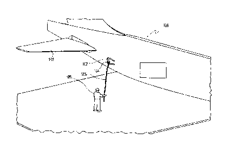
[00271 Turning now to Fig. 1, a tail portion of an exemplary aircraft 100
(e.g., Boeing 737) is
shown. In this aircraft 100, the APUs, one on each side, are located inside
the aircraft body (not
shown). The air inlets 102 to the APUs are provided on either side of the
aircraft 100 just in
front of the rear wings 103. Also shown in Fig. 1 is a cleaning operator 105
using a spray
cleaning device 104 according to an embodiment (the water supply system for
providing high
pressure water is not shown). As shown in Fig. 1, the spray cleaning device
104 is operated from
the ground while the operator 105 holds the cleaning device 104 with his
hands. Due to the
elongated water supply pipe 106, the air inlet 102 for the APU can be used to
access the turbine
for cleaning purposes without the need of ladders or lift devices.
[00281 Fig. 2 illustrates an exemplary embodiment of a spray cleaning device
230. The device
230 comprises a spray nozzle 232, the design of which will be discussed in
more detail below.
The nozzle 232 is attached to a nozzle tube 234 (i.e. a tube carrying the
nozzle), which is shown
bent at a bending angle of about 90 , although other angles may be appropriate
for specific
applications, mainly depending on the design of the APU, and/or its position
in an aircraft body.
The bending radius of the tube 234 is not critical, but should of course be
such that liquid flow
there through is not restricted.
[00291 Attached to the tube 234 is an adjustable positioning means 236. In
this embodiment,
the positioning means 236 is shown as a generally "U"-shaped member, wherein
the inner
CA 02691464 2010-02-01
"walls" of the member are configured to conform with the air inlet wall
structure of an aircraft. It
should be understood, however, that this positioning means 236 may be
configured according to
any desired shape, and to confirm to any mounting location.
10030] The spray nozzle carrying tube 234 is attached to (or integral with) a
water supply tube
238 at the distal end thereof. Washing fluid (e.g., water or other washing
fluid, such as
detergents) from a fluid source (not shown) may be injected through the water
supply tube 238,
up through the nozzle tube 234, and out through the nozzle(s) 232. As is
shown, the positioning
means 236 is rigidly connected to the nozzle tube-water supply tube assembly
234-238 with an
angled orientation. In this manner, upon mounting the spray device 230 to an
aircraft inlet, the
spray nozzle(s) 232 will already be aimed in the desired direction. In another
embodiment, the
positioning means 236 may be loosely connected to the nozzle tube-water supply
tube assembly
234-238, in which case the nozzle(s) 232 may be positioned after the spray
device 230 has been
mounted. In such an embodiment, once the nozzle(s) 232 are aimed in a desired
direction, the
positioning means 236 may be tightened and/or locked in place.
100311 Turning now to Fig. 3, the exemplary spray device 230 according to Fig.
2 is shown in
a mounted position at an air inlet 301. As shown, the spray device 230 has
been mounted
directly onto an edge of the air inlet 301. The positioning means 236 is shown
accommodating an
edge of the air inlet 301 to form a firm, temporary connection between the air
inlet 301 and the
spray device 230. Also shown are two bolts 303 on a back side of the
positioning means 236.
These bolts 303 are used to fixedly connect the positioning means 236 to the
nozzle tube-water
supply tube assembly 234-238. As noted above, this enables the spray nozzle(s)
232 to be in a
proper orientation once the spray device 230 has been mounted. It should be
noted, however, that
any known means for fixedly attaching the positioning means 236 to the nozzle
tube-water
6
CA 02691464 2010-02-01
supply tube assembly 234-238 may be utilized without departing from the scope
of the
embodiment. Once the spray device 230 is securely mounted to the air inlet
301, wash fluid 305
from a fluid source (not shown) is injected into the water supply tube 238 and
forced through the
nozzle tube 234, out of the nozzle(s) 232, and into the APU.
[0032] Fig. 4 illustrates an exemplary embodiment of a spray device 440. This
exemplary
embodiment is designed to be rigidly fixed at an air inlet. As a result, it
will be possible to use
flexible hoses for water supply.
[0033] The exemplary spray device 440 comprises one or more nozzles 442, which
are
attached to a nozzle tube 444, which is bent at a bending angle of about 90 .
The tube 444 is
coupled to a further tube section 454 having a hose connection 445 for
coupling a flexible hose
or other water supply tube to the device 440.
[0034] There is also provided a support member 446 comprising a main body
portion 446a
having two wing portions 446b at respective ends thereof. The support member
446 is suitably
made of sheet metal, although any other rigid material may be used. In one
embodiment, the
support member 446 may be constructed from tubes.
[0035] The nozzle tube 444 is rigidly attached, e.g. via welding, to the main
body portion
446a of the support member 446, so as to provide a fixed position of the
nozzle(s) 442 with
respect to an APU when mounted.
[0036] On each wing portion 446b of the support member 446 there is attached a
positioning
bracket 448. These brackets 448 may be essentially "U"-shaped, as shown, or
any other
appropriate shape for conforming to the contour of an edge of an APU air
inlet, and for holding
the spray device 440 in a fixed position in both lateral and vertical
directions.
7
CA 02691464 2010-02-01
[00371 In order to prevent spray forces from forcing the spray device 440 away
from its
desired mounting position, there is provided a fixation means 449. This
fixation means 449
ensures that no uncontrolled movement occurs by abutting to parts of the air
inlet structure (not
shown) with a sufficient force to prevent any unwanted movement. This can be
achieved either
purely by friction forces on the aircraft body at the air inlet, or by a part
of the fixation means 449
actually abutting some part of the aircraft body to hinder backwards movement
of the spray
device 440.
[00381 In the particular embodiment shown in Fig. 4, the fixation means 449
comprises two
spring-loaded arms 450 arranged in a "V" configuration. The arms 450 are
connected via a
torsion spring 451 which provides a torsion force that urges the arms 450 to
move apart so as to
widen the "V". Optionally, end stops are provided to prevent the arms 450 from
widening too
much. Suitably, the maximum deflection could be set to correspond to a
slightly larger span than
the width of the space in which they are to be clamped. The ends of each arm
450 are preferably
provided with a rubber cap 452 to provide friction when abutting the aircraft
body.
[00391 In an alternative embodiment, one of the arms 450 may be rigid, while
the other arm
450 may be spring-loaded by the torsion spring 451.
[00401 Fig. 5a shows the exemplary device 440 described with respect to Fig.
4, mounted at
an air inlet 501 to an APU of an aircraft. As can be seen, the torsion spring
(not shown) forces
the arms 450 against a part of the structure of the air inlet 501. The
friction between the rubber
caps 452 and the air inlet 501 together with the torsion spring force create a
reaction force that is
large enough to withstand the force from water spray as it travels through the
wash fluid and
nozzle tubes 454, 444. In Fig. 5a, the air inlet 501 comprises surfaces that
have a slight
inclination which helps in creating the reaction force. However, even in a
case where there is
8
CA 02691464 2010-02-01
only an essentially horizontal air inlet surface for the arms 450 to rest
against, the friction from
the rubber caps 452 and the force from the torsion spring may suffice to keep
the spray device
440 in place during operation. In order to mount the spray device 440, or to
reposition the spray
device 440, the arms 450 may be forced towards each other and when the spray
device 440 is in
position, the arms 450 may be released to exert a force against the surface of
the air inlet 501.
[0041] When the spray device 440 is in a mounted position, as in Fig. 5a, the
arms 450 press
against the air inlet 501 and hold the spray device 440 in place. To remove
the spray device 440,
the arms 450 may be forced towards each other against the spring force, as
indicated in Fig. 5b,
thereby removing the friction force from the air inlet 501.
[0042] In an alternate embodiment, a spray device may comprise a remote
control means for
enabling an operator to remotely mount, dismount, and/or position the spray
device. An
exemplary remote control means 600 is shown in Fig. 6. As shown, the remote
control means
600 comprises a wire 660 coupled to arms 662a, 662b of an exemplary spray
device 640 in such
a way that by pulling the wire 660, the arms 662a, 662b are forced towards
each other. The wire
660 may be attached to the lower arm 662b at attachment point 670, and looped
around a pulley
wheel 664 on the upper arm 662a, or through a loop or a hole in the upper arm
662a (not shown).
The wire 660 may then be pulled along the tube 665 in suitable guide
members/structures, which
in one embodiment could be implemented in the form of short tube segment(s)
668 attached to
the tube 665. When the wire 660 is pulled, the wire 660 will cause the lower
arm 662b to move
upwards and the upper arm 662a to move downwards (as shown by the arrows in
the figure),
thereby reducing the gap between the arms 662a, 662b. Once the wire 660 is
released, the arms
662a, 662b will move apart from one another, creating tension against an air
inlet structure.
9
CA 02691464 2010-02-01
[0043] In an alternative embodiment, a motor and a gear mechanism (not shown)
may be
provided for mechanically opening and closing the arms 662a, 662b. This
motor/gear
mechanism could then be controlled by a remote operator. The motor, similar to
the wire 660
could be used to drive the arms 662a, 662b in opposite directions either
inwards to release them
from a mounted position, or outwards to lock them in position.
[0044] With reference to the flowchart of Fig. 7, a method for cleaning one or
more APUs is
provided. As an initial step 710, a novel spray cleaning device, as disclosed
herein, is provided.
The cleaning device may comprise one or more nozzles for spraying washing
fluid onto one or
more APUs, a water tube for supplying washing fluid to said nozzles, and a
positioning means
for positioning the one or more nozzles in a desired orientation. The
positioning means may
optionally further comprise a clamping member adapted to engage an air inlet
structure of an
aircraft. Optionally, the positioning means may also include a support member,
for use in holding
the spray cleaning device against a portion of the aircraft body. Connected to
an end of the water
tube may be a rigid elongated tube made of any suitable rigid material, or a
flexible hose made of
any suitable flexible tubing. Optionally, the rigid elongated tube may be
telescopically
extendable, thereby enabling an operator to raise and lower the spray cleaning
device.
[0045] Once the spray cleaning device is provided, at 720, it may be engaged
onto an air inlet
structure of the aircraft via the clamping member. Optionally, if the
positioning means includes a
support member, an operator may hold the support member against a portion of
the aircraft body.
As will be appreciated by those in the art, utilizing the support member in
this manner will
provide further stability and support to the cleaning device while in
operation. Indeed, depending
on the implementation, the support member may be utilized without having to
engage the
clamping member at all.
CA 02691464 2010-02-01
[0046] At 730, after the spray cleaning device has been properly engaged,
washing fluid from
a fluid source may be provided through the nozzles via the water tube at a
desired spray pressure,
spray temperature, and spray droplet size.
[0047] Optionally, as noted above, the spray cleaning device may include two
arms in a V-
configuration. In such an embodiment, the method may further comprise urging
the two arms
together, positioning the spray cleaning device, and then releasing the two
arms. If the arms are
spring loaded, the force generated as a result of the spring loading will
cause the two arms to
move apart and against portions of the aircraft. Preferably, the spring
loading is selected to
provide sufficient force to maintain the spray cleaning device stable and in
position during a
washing operation. In embodiments where a remote control mechanism is used to
operate the
arms, the method may further comprise manually or mechanically urging the two
arms apart prior
to position the spray cleaning device, and then releasing the two arms to
engage portions of the
aircraft.
[0048] Upon completing the washing operation, the spray cleaning device may be
removed
from the air inlet structure via unclamping the clamping member, releasing the
support member,
and/or urging the two arms together, depending on which form of spray cleaning
device is
implemented.
[0049] The foregoing examples are provided merely for the purpose of
explanation and are in
no way to be construed as limiting. While reference to various embodiments are
shown, the
words used herein are words of description and illustration, rather than words
of limitation.
Further, although reference to particular means, materials, and embodiments
are shown, there is
no limitation to the particulars disclosed herein. Rather, the embodiments
extend to all
11
CA 02691464 2010-02-01
functionally equivalent structures, methods, and uses, such as are within the
scope of the
appended claims.
12