Note : Les descriptions sont présentées dans la langue officielle dans laquelle elles ont été soumises.
CA 02692935 2010-02-15
-1-
Bone screw and method of manufacturing same
Technical Field
The disclosure relates to a self-tapping bone screw, in particular for use as
a com-
pression screw or a locking screw for an implant. The disclosure further
relates to a
manufacturing method for such a bone screw.
Technical Background
Bone screws are screws which are screwed into bones. Basically, bone screws
are
used in two different ways: In a first application bone screws serve to fix
bones or
bone fragments in a desired position relative to one another. In this case,
the bone
screw is used alone. In a second application the bone screw is used as a
compres-
sion screw or a locking screw in order to position additional elements as
fixation
elements in or on the bone. Here, bone screws are used, for example, together
with
marrow nails. Another area of application is osteosynthesis, in which a
biocompatible
element substitutes for a bone or a bone fragment. For example, a plate made
of
titanium can be anchored by bone screws to the skull, as a replacement for a
skull
fragment.
Bone screws are available in a large number of variations for special
applications.
Thus, for example, US 6,030,162 discloses a bone screw for generating an axial
compression, so that bone fragments are pressed together by the screwed-in
screw.
The compression is generated, inter alia, by providing a plurality of threaded
portions
having different thread pitches.
In many cases, the screw shank of a bone screw is cylindrically shaped. From
EP 0
491 211 Al there is known a bone screw which has a head-side, cylindrical
first
shank portion and a tip-side second and likewise cylindrical shank portion
adjoining
the first shank portion, the first shank portion having a greater root (or
core) diame-
ter than the second shank portion. In yet other cases, bone screws have a
conically
shaped screw shank widening from the tip towards the head.
From WO 2007/048267 Al there is known a bone screw in which a root diameter in
a pre-forming region located at the tip of the screw is greater than the root
diameter
in an intermediate region adjoining the pre-forming region. An outside
diameter of
CA 02692935 2010-02-15
-2-
the screw in the pre-forming region is likewise greater than an outside
diameter in
the intermediate region.
Self-tapping screws have the advantage that a thread does not have to be pre-
cut in
the bone. Such screws have a screw shank with at least one threaded portion.
The
thread is suitably configured with respect to properties such as thread
profile, flank
angle, etc., so that the screw cuts its thread itself when the surgeon screws
it into
the bone material.
io A fundamental problem with self-tapping bone screws are the, in some cases,
con-
siderable screwing-in forces which arise when screwing the screw into the
bone. The
material of a bone behaves to a certain extent elastically when being cut
through;
that is to say the bone material strives to return to its initial position
after being cut
through. This increases the force to be applied by the surgeon, and to a
considerable
extent as the penetration depth increases. The problem is further aggravated
when
the surgeon operates in a small area, for example in the face or skull region.
Brief outline
zo The object on which the invention is based is to propose a self-tapping
bone screw in
which the screwing-in forces are reduced without the secure and exact-fitting
seating
of the screw and hence its function being adversely affected.
In order to achieve this object, according to a first aspect a self-tapping
bone screw
is proposed. The bone screw has a screw shank, which has a front tip, a
cutting
region, an intermediate region and a rear head region. A thread extends, in a
threaded portion of the screw shank, over a transition region comprising
mutually
adjoining parts of at least the cutting region and the intermediate region. An
outside
diameter and a root diameter of the screw shank are defined by the thread in
the
threaded region. In the transition region the root diameter of the screw shank
in the
cutting region is greater than the root diameter of the screw shank in the
intermedi-
ate region. Furthermore, in the transition region the outside diameter of the
screw
shank is constant.
The root diameter at the transition from the cutting region to the
intermediate region
may be stepped, for example in the shape of a single step or a plurality of
steps. In
some variants of the proposed bone screw, the root of the cutting region has a
con-
CA 02692935 2010-02-15
-3-
vex shape. In other variants, the root of the cutting region is stepped.
Mixtures of a
convex and stepped contour are also conceivable. Regardless of that, the root
diame-
ter of the screw shank in the intermediate region may be constant or else
vary. The
outside diameter of the screw shank in the threaded portion may be constant in
the
intermediate region. In some realizations of the bone screw, the thread
extends
continuously over the cutting region and the intermediate region (and possibly
also
into the head region). The thread may have a constant thread pitch.
The thread may be designed in the cutting region as a trapezoidal thread, at
least in
regions. In the intermediate region, the thread may be constituted as a
triangular
thread. In certain realizations of the bone screw, the thread runs out at the
tip. Re-
gardless of this, the tip may be designed as a centring tip. For example, the
tip may
be designed in a stepped or rounded manner.
According to one variant of the bone screw, the latter has a groove, extending
over
at least the tip and the cutting region, for removing cut material. Two, three
or more
such grooves may also be provided.
The head region of the bone screw may have a thread. In other realisations,
the
head region is thread-free. The outside diameter of the head region may be
greater
than the outside diameter of the intermediate region. The root diameter of the
head
region may also be greater than the root diameter of the intermediate region.
According to one alternative, the bone screw has a thread extending
continuously
from the tip up to the head region. In a variant of this realization, the head
region
has a root diameter or outside diameter which is enlarged in each case in
relation to
the intermediate region. In another variant, the root diameter and outside
diameter
in the head region and intermediate region are constant.
In one variant, the bone screw has a tip-side threaded portion and a head-side
threaded portion. The threaded portions are separated from one another by a
thread-free part of the intermediate region. The threads in the two threaded
portions
may run synchronously with one another. The head region with the head-side
threaded portion may have a greater root diameter and outside diameter than
the
intermediate region.
CA 02692935 2010-02-15
-4-
One realization of the bone screw discussed here is intended for use as a
locking
screw for an implant such as a bone plate. The bone screw may also be used as
a
compression screw either together with an implant (such as a bone plate) or
without
an implant. The compression screw may, for example, be utilized for
compressing the
bone to the implant, in which case the bone screw may be realized with a
thread-free
head. Realizations of the bone screw with a threaded head may be utilized in
locking
scenarios to lock the screw head to the plate. To this end, a plate hole
receiving the
bone screw may comprise a thread that is complementary to the thread on the
head
of the bone screw.
Furthermore, according to a further aspect a method for manufacturing a self-
tapping bone screw is proposed. The bone screw has a screw shank, which has a
front tip, a cutting region, an intermediate region and a rear head region. A
thread
extends, in a threaded portion of the screw shank, over a transition region
compris-
ing mutually adjoining parts of at least the cutting region and the
intermediate re-
gion. An outside diameter and a root diameter of the screw shank are defined
by the
thread in the threaded region. The method comprises the step of guiding a
milling
tool for producing the thread in the threaded portion in such a way that the
thread
teeth are cut less deeply in the cutting region than in the intermediate
region. In this
way, in the transition region the root diameter of the screw shank in the
cutting
region is greater than the root diameter of the screw shank in the
intermediate re-
gion. In addition, the outside diameter of the screw shank is constant.
Brief Description of the Drawings
Further aspects and advantages of the invention will become apparent from the
following description of preferred embodiments and from the figures, in which:
Fig. 1 shows a side view of a first embodiment of a bone screw;
Fig. 2 shows a side view of the bone screw from Fig. 1 rotated by 900;
Fig. 3 shows an enlarged side view of a front portion of the bone screw from
Fig. 1;
Fig. 4 shows an enlarged side view of a front portion of the bone screw from
Fig. 2;
Fig. 5 shows a top view of the tip of the bone screw from Fig. 1;
CA 02692935 2010-02-15
-5-
Fig. 6 shows a side view of a front portion of a screw blank;
Fig. 7 shows a section through a front portion of the bone screw from Fig. 1;
Fig. 8 shows a second embodiment of a bone screw having a head region
which is altered in relation to the screw from Fig. 1;
Fig. 9 shows a third embodiment of a bone screw having a head region which
is altered in relation to the screws from Figures 1 and 8;
Fig. 10 shows a fourth embodiment of a bone screw having a head region
which is again altered in relation to the previous examples;
Fig. 11 shows a top view of the tip of the bone screw from Fig. 10;
Fig. 12 shows a section through the cutting region of the bone screw from Fig.
10;
Fig. 13 shows a sectional view of a rear part of the bone screw from Fig. 10;
and
Fig. 14 shows a top view of the head region of the bone screw from Fig. 10.
Detailed Description
Several embodiments of a bone screw are explained below. In different views of
one
and the same embodiment, the same reference symbols are used for identical ele-
ments.
Firstly, with reference to Figures 1-7, a first embodiment of a bone screw 100
which
can be provided for example as a locking screw for use in osteosynthesis in
the
face/skull region is explained. Fig. 1 shows a side view of the bone screw
100, which
is designed as a self-tapping screw. The bone screw 100 has a screw shank 102
with
a front tip 104, a cutting region 106, an intermediate region 108 and a head
region
110. A thread extends over a threaded portion 112 which extends, in this
embodi-
ment, continuously from the tip 104 right up into the head region 110. In the
front
CA 02692935 2010-02-15
-6-
region of the screw shank 102, two helically wound grooves 116 and 118 for
remov-
ing cut material are provided.
Fig. 2 shows the bone screw 100 in a view rotated by a quarter turn about the
longi-
tudinal axis. A detail of the side views of the screw 100 from Figs. 1 and 2
(see in
Fig. 2 the detail denoted by the circle 120) is illustrated in enlarged manner
in Figs. 3
and 4, respectively. It can be seen, for example, from Fig. 4 that the groove
116
extends over the tip 104 and the cutting region 106 into the intermediate
region 108
and runs out.there. Instead of two grooves, it is also possible for only one
groove or
several grooves, for example 3 or 4 grooves, to be provided. Fig. 5 shows a
view,
from the front, of the tip 104 of the screw 100. The grooves 116 and 118 and
also
the head part 122 (cf. Fig. 1) of the head region 110 can be seen.
The cutting region of the self-tapping screw 100 comprises that tip-side and
threaded
region 106 of the screw 100 which cuts the mating thread into the bone
material.
This is the region in which the thread reaches and maintains its greatest
outside
diameter, disregarding the fact that the outside diameter and/or root diameter
are
optionally further increased in the head region 110. At the head side, the
cutting
region 106 ends at the location at which both the greatest outside diameter
and the
greatest root diameter are reached and the root diameter (or the outside
diameter,
or both diameters) decreases in the direction of the intermediate region 108.
In the case of the screw 100, the root diameter of the cutting region 106 is
increased
in relation to that of the intermediate region 108. Generally, it is the case
that, if only
the root diameter is considered, the tip-side portion of the screw 100 can
have, for
example, a crowned shape. For this purpose, the root diameter in the cutting
region
106 can vary, for example, in the shape of a convex curve, while in the
adjoining
part of the intermediate region (and possibly also the tip) it is constant. In
the exam-
ple of the bone screw 100, the root diameter in the region of the cutting
region 106
is less crowned, but rather constant. Intermediate shapes between a crowned
shape
and a constant, enlarged root diameter are possible, for example a root
diameter
with a plurality of steps in the cutting region.
A transition region 114 is defined between the cutting region 106 and the
intermedi-
ate region 108 as a result of the root diameter of the cutting region 106
merging into
the root diameter of the intermediate region 108 here. As is evident from the
figures,
the intermediate region 108 has itself a constant root diameter. The outside
diameter
CA 02692935 2010-02-15
-7-
of the screw shank 102, when seen from the tip, reaches its greatest value in
the
cutting region 106 and is constant in the further course in the cutting region
106 and
the intermediate region 108.
A screw blank 200, from which the screw 100 is machined, is shown
schematically in
Fig. 6. The centring tip 104 is produced from a region 202, the cutting region
106
from a region 204 and the intermediate region 108 from a region 206. The
region
202 comprises the rounded segment 208 and the two trapezoidal segments or
spherical caps 210 and 212, each having different opening angles, from which
the
stepped shape of the subsequent centring tip 104 results. The segment 210
remains
thread-free, and the threaded portion 112 begins at the segment 212. Further
seg-
ments 214 and 216 are cylindrically shaped. The root diameter which is
thickened in
the cutting region 106 in relation to the intermediate region 108 is formed
only in the
course of the thread milling.
In other embodiments, instead of the stepped tip shown in Fig. 6, continuous
shapes
may also be used. Generally, the tip is advantageously provided as a centring
tip with
the thread running out.
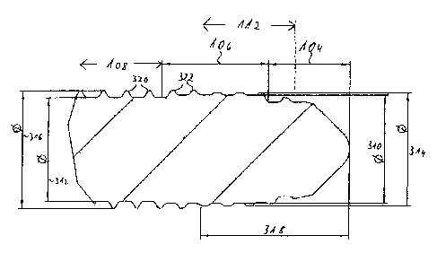
Fig. 7 is a cross-section through the part of the bone screw 100 shown in Fig.
4, with
the tip 104 which opens at a right angle, the cutting region 106 and the tip-
side part
of the intermediate region 108.
The greatest root diameter 310 of the threaded region 112 is reached in the
cutting
region 106. Over the cutting region 106, the root diameter is constant. In the
transi-
tion region 114 between the cutting region 106 and the intermediate region
108, the
root diameter decreases to a smaller value 312, which is maintained over the
inter-
mediate region 108. The outside diameter increases from the tip 104 via a
value 314
at the transition to the cutting region 106 and reaches its maximum value 316
in the
cutting region 106. The outside diameter is constant with the value 316 in the
transi-
tion region 114 and in the intermediate region 108.
As can be seen from Fig. 7, in the case of the bone screw 100 described by way
of
example here, the transition from the enlarged root diameter 310 in the
cutting re-
gion 106 to the smaller root diameter 312 in the intermediate region 108 takes
place
in a stepped manner, that is to say the transition takes place in the region
114 in the
shape of a single step. In other embodiments of the bone screw, the stepping
can
CA 02692935 2010-02-15
-8-
instead be carried out in the form of a plurality of steps, or the root
diameter is re-
duced in the transition region, for example, in the shape of a convex curve.
Mixtures
of stepped and continuous reduction of the root diameter are also possible.
In the case of the single-step transition, shown in Fig. 7, from the constant
root
diameter 310 in the cutting region 106 to the constant root diameter 312 in
the in-
termediate region 108, the transition region 114 is identical to the boundary
between
the cutting region 106 and the intermediate region 108. In other embodiments,
in
which the root diameter between the cutting and intermediate regions decreases
in a
plurality of steps and/or continuously, the transition region is accordingly
more ex-
tensive.
In the example of the bone screw 100, the root diameter 312 in the
intermediate
region is constant. Generally, it is not absolutely necessary for the root
diameter in
the intermediate region to be constant. However, the root diameter in the
intermedi-
ate region should be less than the root diameter in the cutting region.
Furthermore,
in the embodiment of the bone screw 100 shown in Figs. 1-7, the root diameter
310
in the cutting region 106 is constant. In other embodiments, the root diameter
in the
cutting region may vary, and may describe, for example, a convex curve as a
whole
or piece by piece, for example at the transition from the tip to the cutting
region (in
Fig. 7 the transition of the root diameter from the tip 104 to the cutting
region 106
takes place in a stepped manner).
Since the root diameter 310 in the cutting region 106 is greater than the root
diame-
ter in the intermediate region 108, a larger hole is cut by the cutting region
106 than
that which corresponds to the root diameter 312 in the intermediate region
108. As a
result, with respect to the bone which has been cut through, the bearing
surface of
the screw 100 and the penetration depth of the thread teeth 320 are reduced in
the
intermediate region 108. This leads to a reduction of the screwing-in forces
of the
screw 100 into the bone. In order that the screw 100 after being screwed in
does not
lie loosely, in the intermediate region 108, in the mating thread cut by the
cutting
region 106, the cut geometry should correspond. That is to say the thread in
the
cutting region 106 and the intermediate region 108 should be designed
continuously
and with a constant thread pitch. If, alternatively, a plurality of threaded
portions
(separated by thread-free portions) are provided in the cutting region and in
the
intermediate region, these should correspond to one another, i.e. the threads
should
be synchronous with one another.
CA 02692935 2010-02-15
-9-
As can be seen in particular in Figs. 3, 4 and 7, the thread profile changes
at the
transition from the intermediate region 108 to the cutting region 106. While
in the
cutting region 106 (and in the threaded part running out in the tip 104) the
thread is
shaped trapezoidally with a comparatively large surface of the teeth (outer
surface of
the screw), cf. the thread teeth 322 in Fig. 7, the thread shape in the
intermediate
region 108 corresponds to a trapezoidal thread with a comparatively smaller
surface
of the teeth (more acute thread teeth), cf. the thread teeth 320. In other
embodi-
ments, a triangular thread may be present in the intermediate region.
Regardless of
io this, the edges of the screw 100 are generally cut off, so that the thread
teeth 320
are also rounded to a certain extent.
The trapezoidal cross-section of the thread turns in the cutting region 106
serves in
particular for cutting through the bone material on screwing in, while the
cutting
function of the triangular thread in the intermediate region 108 is less
important. In
the intermediate region 108, the thread is intended in particular to fit into
the thread
turns which have already been cut, without the screwing-in resistance
significantly
increasing as a result.
In the case of a method for producing the screw 100 from the screw blank 200,
a
milling tool can be used to produce the thread. In this method, the milling
tool can
be guided, for example, over a convex curve or a stepping with one or more
steps.
The thread teeth are thereby cut less deeply in the cutting region 106 than in
the
intermediate region 108, thus resulting in the enlarged root diameter 310 in
the
cutting region 106 in relation to the root diameter 312 of the intermediate
region
316.
Examples of specific dimensions of the bone screw 100 are given below.
Frequently,
valid ranges of values are specified with a lower and upper value in each
case; from
the combination of the lower values, a concrete embodiment of a smaller screw
results, while the combination of the upper values results in a concrete
embodiment
of a larger screw. However, examples which lie outside the specified ranges of
values
are also readily conceivable; the general dimensions of bone screws, in
particular
locking screws, are known to a person skilled in the art. What is important in
the
case of the numerical values specified here are not only the absolute values
but also
the relationship of the values of the various dimensions to one another.
CA 02692935 2010-02-15
-10-
In general, it is the case that a typical effective diameter of the bone screw
100 may
lie, for example, between 2 millimetres (mm) and 8.0 mm, preferably between
2.7
mm and 5.0 mm; smaller or larger effective diameters are likewise possible,
but the
following ranges of values relate to screws having the specified effective
diameters.
The tolerance of the dimensions specified by way of example lies typically in
the
region of 0.1 mm.
Owing to the lack of thread, the circumstances for the screw tip 104 are
explained
with the aid of the screw blank 200 shown in Fig. 6 for greater clarity. The
segment
210 adjoining the rounded tip segment 208 may form a truncated cone with an
opening angle of 900, that is to say the surface lines of the truncated cone
form an
angle of 45 with respect to the screw (blank) axis 218. More acute or more
obtuse
opening angles are likewise possible; however, the self-centring properties of
the
screw should preferably be retained. The truncated cone formed by the
adjoining
segment 212 may have, for example, an opening angle of 24 , i.e. the surface
lines
form an angle of 12 with respect to the screw axis 218.
The cylindrical segment 214 may have a diameter 220, for example, in the range
of
4.9 mm to 2.8 mm. The adjoining blank shank 216 may have, for example, a diame-
ter 222 of 5.1 mm to 3.0 mm. A length of the segments 208, 210, 212 and 214
along
the screw axis 218 may lie, for example, in the range of 6.7 mm to 4.5 mm. A
length
only of the segments 208, 210 and 212 of, for example, 3.76 mm to 2.59 mm
could
then result, and a length only of the segments 208 and 210 of 1.6 mm to 0.55
mm
could result.
Referring to Fig. 7, the nominal diameter 314 at the tip-side part of the
cutting region
106 is, for example, 4.9 mm to 2.8 mm, while the nominal diameter 316 at the
head-
side part of the cutting region 106 is, for example, 5.1 mm to 3.0 mm. The
root
diameter 310 in the cutting region 106 may assume, for example, a value in the
range from 4.7 mm to 2.7 mm. The root diameter 312 in the intermediate region
108
has, in contrast, a smaller value in the range from 4.5 mm to 2.5 mm.
A length of the cutting region 106 along the screw axis 218 (Fig. 6) may lie,
for ex-
ample, between 4.7 mm and 2.0 mm. Accordingly, a length of the tip 104 may lie
between 3.5 mm and 2.7 mm. The length 318 in Fig. 7 indicates the distance
from
the tip of the screw up to the point from which the maximum nominal or outside
CA 02692935 2010-02-15
- 11 -
diameter of the screw 100 is reached. The length 318 may have, for example, a
value between 6.7 mm to 4.5 mm.
The flank angle of the trapezoidal thread in the cutting region 106 may be,
for ex-
ample, 45 .
The groove 116 shown in particular in Fig. 4 may be formed in a manner running
out
to an outside diameter of 4.7 mm to 2.0 mm. The groove pitch of the grooves
116
and 118 may be typically 40 mm. The length 124 of the groove along the screw
axis
126 (cf. Figures 2 and 4) may be between 20 mm to 2 mm and preferably between
12.5 mm to 6.0 mm. However, the length 124 of the groove 116 may be chosen to
be substantially constant at 12.5 mm, almost regardless of the overall length
of the
screw. Only in the case of particularly short screws, for example with a
length of less
than 20 mm, can a shorter length 124 of the groove along the screw axis, for
exam-
pie with a value of 6.2 mm, be provided.
The edges of the grooves 116 and 118 are designed sharp but burr-free. The
grooves 116 and 118 are offset by 180 with a tolerance of, for example, 1 .
Refer-
ring to Fig. 5, the grooves 116 and 118 have at the tip 104 a spacing 128 of 2
mm,
but at least 0.8 mm.
Fig. 8 shows a further embodiment of a bone screw 400. The latter differs from
the
bone screw 100 of the previous figures in the design of the head region. While
in the
case of the head region 110 of the screw 100 (cf. Fig. 1) both the root
diameter and
the outside diameter are enlarged in comparison with the corresponding
diameters of
the intermediate region 108, the head region 402 of the screw 400 has both the
same root diameter and the same outside diameter as the intermediate region
404.
Since the threaded portion 406 usable for screwing in and optionally locking
extends
right up to the head part 408 in the case of the screw 400, the screw shank
410 of
the screw 400 can be designed shorter overall than the screw shank 102 of the
screw 100.
Fig. 9 shows a further embodiment 500 of a bone screw, in which the head
region
502 is designed differently again than in the screws 100 and 400. The head
region
502 is designed in particular thread-free. The diameter of the head region 502
corre-
sponds to the root diameter of the intermediate region 504.
CA 02692935 2010-02-15
-12-
Fig. 10 shows a further embodiment of a bone screw 600. As the preceding
embodi-
ments, the screw 600 also has in the cutting region 602 an enlarged root
diameter in
comparison with the intermediate region 604. The outside diameter of the screw
is
constant in the cutting region and in the intermediate region. The obtuse
screw tip
606 has an opening angle of 900. A head region 608 has an enlarged head part
610
with its own thread.
Fig. 11 shows the screw 600 from the front and Fig. 12 shows a section through
the
screw 600 along the line D-D in the cutting region 602. There can be seen two
taper-
ing grooves 612, 614 which can be configured in the same way as for the
grooves
116, 118 of the screw 100. The grooves 612 and 614 are offset by 180 . Further-
more, the thread of the head part 610 can be seen.
Fig. 13 is a sectional view of the rear part of the screw 600. As can be seen
from the
two Figures 10 and 13, the front threaded portion 616 in the intermediate
region 604
ends at the head region 608, which thus has a thread-free portion 618. The
head
part 610 has a diameter significantly enlarged in relation to the intermediate
region
604, that is to say both the root diameter and the outside diameter of the
threaded
head part 610 are greater than the corresponding diameter of the intermediate
re-
gion 604. The threads in the threaded portion 616 and in the head part 610 run
synchronously with one another. The thread in the head part 610 may be a two-
start
thread.
As with the design for the example of the bone screw 100, the thread teeth 620
in
the case of the screw 600 too (cf. Fig. 13) may be configured as narrow
trapeziums
(in particular in comparison with the thread teeth in the cutting region),
thus result-
ing in an acute trapezoidal thread. Alternatively, the thread in the
intermediate re-
gion may also be designed as a triangular thread, it being possible for the
thread
teeth to be cut off.
The head region 608 is configured with a recess 622 for receiving a wrench,
for
example as a hexalobular internal driving feature. Fig. 14 is a top view of
the rear
end of the screw 600 with the head region 608 and recess 622.
An overall length of the screw 600 may lie, for example, between 8 mm and 150
mm, preferably between 14 mm and 120 mm. The length of the head part 612 along
the screw axis 624 may be, for example, 3.2 mm. The thread-free portion 618
may
CA 02692935 2010-02-15
- 13-
have a length of 1.3 mm. With an effective diameter of the screw 600 of 4.7 mm
in
the intermediate region 604, the root diameter may be 4.5 mm in the
intermediate
region 604 (4.7 mm in the cutting region 602) and the outside diameter may be
5.1
mm in the intermediate region 604 and the cutting region 602. The thickened
head
part 610 may in this case have a root diameter of 5.8 mm and an outside
diameter of
6.5 mm.
The thread teeth 620 may have a spacing of 1 mm between the teeth and have an
upper trapezium surface of 0.1 mm. The spacing between the bases of two thread
teeth on the screw shank may be approximately 0.323 mm.
The outer diameter 626 of the hexalobular internal driving feature 622 may be,
for
example, 3.95 mm and the innermost diameter 628 of the hexalobular internal
driv-
ing feature 622 may be 2.85 mm, in each case with a tolerance of a few
hundredths
of a millimetre.
All of the bone screws described here may be used as compression screws or
locking
screws for an implant. While the front part in the case of the bone screws
100, 400,
500 and 600 is configured in each case in the same way, in particular with
respect to
the enlarged root diameter in the cutting region, the screws are adapted by
means of
their head region to respectively different applications, for example to
different fixa-
tion elements. The material used for the bone screws illustrated by way of
example
here may be special steel or titanium.
The bone screws discussed above can be screwed into bones or bone fragments
with
a reduced screwing-in force in relation to conventional screws. The enlarged
root
diameter in the cutting region of the bone screw (in comparison with the root
diame-
ter of the intermediate region) has the effect that the bearing surface of the
screw in
the intermediate region is reduced, and at the same time the penetration depth
of
the thread teeth can be reduced. A threaded portion (or a plurality of
separate, syn-
chronous threaded portions) extending continuously from the cutting region up
to
the intermediate region and optionally to the head region ensure that the cut
geome-
try corresponds. Thus, the intermediate region of the screw situated behind
the
cutting region fits exactly, on screwing in, into the cut mating thread in the
bone. A
constant thread pitch is advantageously provided here.
CA 02692935 2010-02-15
-14-
In order to ensure a secure seating of the screw also in the intermediate
region, the
thread shape may vary between the cutting region and the intermediate region,
for
example from a trapezoidal to a triangular thread, or from a more obtuse
trapezoidal
thread to a more acute trapezoidal thread. Other thread shapes are likewise
conceiv-
able, insofar as they ensure the functionality of a self-tapping screw. The
constant
outside diameter in the transition region, and preferably also along at least
a sub-
stantial part of the intermediate region ensures the optimal seating of the
screw
here. A thread extending continuously from the cutting region over the entire
inter-
mediate region further improves the exact-fitting seating here, without the
screwing-
in forces substantially increasing. One or more groove may be provided in
order to
remove cut material without thereby impairing the functionality of the screw
with
respect to the reduction of the screwing-in forces with a secure seating.
Depending on the specific application, it may be expedient to provide in the
head
region a head part which is enlarged with respect to the root diameter and/or
outside
diameter in order to ensure a secure seating of the bone screw in the bone
material
and/or a further implant element. The correspondingly thickened head part may
have
its own, optionally synchronous thread, or a continuous threaded portion
extends
from the intermediate region into the head region.
The embodiments illustrated here represent only a few expedient embodiments of
the invention. Within the scope of the invention specified by the following
claims,
many other embodiments besides will be conceivable by those skilled in the
art.