Note : Les descriptions sont présentées dans la langue officielle dans laquelle elles ont été soumises.
CA 02694432 2010-02-23
r -
-1-
METHODS OF FORMING EROSION-RESISTANT COMPOSITES,
METHODS OF USING THE SAME, AND EARTH-BORING TOOLS
UTILIZING THE SAME IN INTERNAL PASSAGEWAYS
PRIORITY CLAIM
This application claims the benefit of the filing date of United States Patent
Application Serial No. 12/398,066, filed March 4, 2009, for "Methods of
Forming
Erosion-Resistant Composites, Methods of Using the Same, and Earth-Boring
Tools
Utilizing the Same in Internal Passageways."
TECHNICAL FIELD
The present invention relates generally to methods of forming wear-resistant
materials, methods of using wear-resistant materials to form earth-boring
tools having
increased wear-resistance and earth-boring tools including wear-resistant
material.
More particularly, the present invention relates to earth-boring tools and
components
thereof that are relatively resistant to erosion caused by the flow of fluid
through fluid
passageways extending therethrough, to methods of forming such earth-boring
tools,
and methods of forming erosion-resistant materials for use in such tools.
BACKGROUND
Earth-boring tools are commonly used for forming (e.g., drilling and
reaming) well bore holes (hereinafter "wellbores") in earth formations. Earth-
boring
tools include, for example, rotary drill bits, core bits, eccentric bits,
bicenter bits,
reamers, underreamers, and mills.
Earth-boring rotary drill bits have several configurations. One configuration
is the fixed-cutter drill bit, which typically includes a plurality of wings
or blades
each having multiple cutting elements fixed thereon. Another configuration is
the
roller cone bit, which typically includes three cones mounted on supporting
bit legs
that extend from a bit body, which may be formed from, for example, three bit
head
sections that are welded together to form the bit body. Each bit leg may
depend
from one bit head section. Each roller cone is configured to rotate on a
bearing shaft
that extends from a bit leg in a radially inward and downward direction from
the bit
leg. The cones are typically formed from steel, but they also may be formed
from a
CA 02694432 2010-02-23
-2-
particle-matrix composite material (e.g., a cermet composite such as cemented
tungsten carbide). Cutting teeth for cutting rock and other earth formations
may be
machined or otherwise formed in or on the outer surfaces of each cone.
Alternatively, receptacles are formed in outer surfaces of each cone, and
inserts
formed of hard, wear-resistant material, in some instances coated with a
superabrasive material such as polycrystalline diamond, are secured within the
receptacles to form the cutting elements of the cones.
A rotary drill bit may be placed in a bore hole such that the cutting
structures
thereof are adjacent and in contact with the earth formation to be drilled. As
the drill
bit is rotated under longitudinal force applied to a drill string to which the
rotary drill
bit is secured, the cutting structures remove the adjacent formation material.
It is known in the art to apply wear-resistant materials, such as so-called
"hardfacing" materials, to the formation-engaging surfaces of rotary drill
bits to
minimize wear of those surfaces of the drill bits caused by abrasion. For
example,
abrasion occurs at the formation-engaging surfaces of an earth-boring tool
when
those surfaces are engaged with and sliding relative to the surfaces of a
subterranean
formation in the presence of the solid particulate material (e.g., formation
cuttings
and detritus) carried by conventional drilling fluid. For example, hardfacing
may be
applied to cutting teeth on the cones of roller cone bits, as well as to the
gage
surfaces of the cones. Hardfacing also may be applied to the exterior surfaces
of the
curved lower end or "shirttail" of each bit leg, and other exterior surfaces
of the drill
bit that are likely to engage a formation surface during drilling. Hardfacing
also
may be applied to formation-engaging surfaces of fixed-cutter drill bits.
During drilling, drilling fluid is pumped down the wellbore through the drill
string to the drill bit. The drilling fluid passes through an internal
longitudinal bore
within the drill bit and through other fluid conduits or passageways within
the drill
bit to nozzles that direct the drilling fluid out from the drill bit at
relatively high
velocity. The nozzles may be directed toward the cutting structures to clean
debris
and detritus from the cutting structures and prevent "balling" of the drill
bit. The
nozzles also may be directed past the cutting structures and toward the bottom
of the
wellbore to flush debris and detritus off from the bottom of the wellbore and
up the
annulus between the drill string and the casing (or exposed surfaces of the
CA 02694432 2011-12-20
-3-
formation) within the wellbore, which may improve the mechanical efficiency of
the
drill bit and the rate of penetration (ROP) of the drill bit into the
formation.
It is known in the art to use flow tubes to direct drilling fluid to a nozzle
and
out from the interior of a drill bit, particularly when it is desired to
direct drilling
fluid past the cones of a roller cone drill bit and toward the bottom of the
wellbore.
Such flow tubes may be separately formed from the bit body, and may be
attached to
the bit body (e.g., bit head section or bit leg) by, for example, welding the
flow tubes
to the bit body. A fluid course or passageway is formed through the bit body
to
provide fluid communication between the interior longitudinal bore of the
drill bit
and the fluid passageway within the flow tube.
As drilling fluid is caused to flow through the flow tubes and/or fluid
passageways within a drill bit, the drilling fluid erodes away the interior
surfaces of
the flow tube and bit body. Such erosion may be relatively more severe at
locations
at which the direction of fluid flow changes, since the drilling fluid
impinges on the
interior surfaces of the flow tube or bit body at relatively higher angles at
such
locations. This erosion can eventually result in the formation of holes that
extend
completely through the walls of the flow tube or bit body, thereby allowing
drilling
fluid to exit the flow tube or bit body before passing through the nozzle,
which
eventually leads to failure of the designed hydraulic system of the drill bit.
When
the hydraulic system of the drill bit fails, the rate of penetration decreases
and the
drill bit becomes more susceptible to "balling." Ultimately, the drill bit may
fail and
need to be replaced.
DISCLOSURE OF THE INVENTION
Embodiments of the present invention include multi-layer films for use in
forming a layer of hardfacing on a surface of a tool. The films include a
first layer that
includes a first polymer material and a first plurality of particles dispersed
throughout
the first polymer material. A second layer covers at least a portion of a
surface of the
first layer and includes a second polymer material and a second plurality of
particles
dispersed throughout the second polymer material. Additional embodiments of
the
present invention include intermediate structures formed during fabrication of
an
earth-boring tool.
CA 02694432 2011-12-20
-4-
Accordingly, in one aspect of the present invention there is provided an
intermediate structure formed during fabrication of an earth-boring tool,
comprising:
a body of an earth-boring tool having a fluid passageway extending at least
partially through the body of the earth-boring tool; and
a multi-layer film disposed over at least a portion of a surface of the body
of the
earth-boring tool within the fluid passageway, the multi-layer film
comprising:
a first layer comprising a paste including a first polymer material and a
first plurality of particles dispersed throughout the first polymer material,
the first
plurality of particles comprised of hard particles, the first layer disposed
on the at least
a portion of a surface of the body of the earth-boring tool within the fluid
passageway;
and
a second layer comprising a film of solid material covering at least a
portion of a surface of the first layer on a side thereof opposite the at
least a portion of a
surface of the body of the earth-boring tool within the fluid passageway, the
second
layer comprising a second polymer material and a second plurality of particles
dispersed throughout the second polymer material, the second plurality of
particles
comprised of metal or metal alloy particles.
According to another aspect of the present invention there is provided a
method
of applying hardfacing to a surface of an earth-boring tool, comprising:
providing a first material layer comprising a paste including a plurality of
hard
particles and a first polymer material on a surface of a body of an earth-
boring tool
within a fluid passageway extending at least partially through the body of the
earth-
boring tool;
providing a second material layer comprising a solid film including a
plurality
of metal matrix particles and a second polymer material adjacent the first
material layer
on a side thereof opposite the body of the earth-boring tool;
heating the body of the earth-boring tool to a first temperature while the
first
material layer and the second material layer are on the body of the earth-
boring tool
and removing the first polymer material and the second polymer material from
the
body of the earth-boring tool; and
heating the body of the earth-boring tool to a second temperature higher than
the first temperature and sintering at least the plurality of metal matrix
particles to form
a layer of hardfacing material on the surface of the body of the earth-boring
tool
CA 02694432 2011-12-20
-5-
comprising the plurality of hard particles dispersed throughout a metal matrix
phase
formed from the plurality of metal matrix particles.
BRIEF DESCRIPTION OF THE DRAWINGS
While the specification concludes with claims particularly pointing out and
distinctly claiming that which is regarded as the present invention, various
features
and advantages of this invention may be more readily ascertained from the
following
description of the invention when read in conjunction with the accompanying
drawings, in which:
FIG. 1 illustrates an embodiment of an earth-boring rotary drill bit according
to
the present invention;
FIG. 2 is a simplified cross-sectional view of an embodiment of a multi-layer
film that may be used to form a layer of hardfacing on surfaces of an earth-
boring tool,
such as the earth-boring rotary drill bit shown in FIG. 1;
FIG. 3 is a simplified cross-sectional view of an embodiment of a multi-layer
film that may be used to form a layer of hardfacing on surfaces of an earth-
boring tool;
FIG. 4 is a partial cross-sectional view of a body of an earth-boring tool
illustrating a multi-layer film like that shown in FIG. 2 on a surface within
a fluid
passageway extending through the body of the earth-boring tool;
FIG. 5 is a partial cross-sectional view of a portion of the body of the
earth-boring tool shown in FIG. 4 illustrating a layer of hardfacing material
formed
from the multi-layer film;
FIG. 6A is an isometric view of an embodiment of a flow tube according to the
present invention that may be used with earth-boring tools, such as the rotary
drill bit
shown in FIG. 1;
FIG. 6B is a side view of the flow tube shown in FIG. 6A;
FIG. 6C is a front view of the flow tube shown in FIGS. 6A and 6B;
FIG. 6D is a longitudinal cross-sectional view of the flow tube shown in
FIGS. 6A-6C taken along section line 6D-6D shown in FIG. 6C;
FIG. 6E is a transverse cross-sectional view of the flow tube shown in
FIGS. 6A-6D taken along section line 6E-6E shown in FIG. 6C;
CA 02694432 2010-02-23
-6-
FIG. 6F is a longitudinal cross-sectional view (like that of FIG. 6D) of the
flow
tube shown in FIGS. 6A-6E illustrating erosion of the interior walls of the
flow tube
that may occur during drilling due to the flow of drilling fluid through the
flow tube;
FIG. 7A is an isometric view of another embodiment of a flow tube according
to the present invention that may be used with earth-boring tools, such as the
rotary
drill bit shown in FIG. 1;
FIG. 7B is a front view of the flow tube shown in FIG. 7A;
FIG. 7C is a longitudinal cross-sectional view of the flow tube shown in
FIGS. 7A-7B taken along section line 7C-7C shown in FIG. 7B; and
FIG. 7D is a transverse cross-sectional view of the flow tube shown in
FIGS. 7A-7C taken along section line 7D-7D shown in FIG. 7B.
MODE(S) FOR CARRYING OUT THE INVENTION
As used herein, the term "abrasion" refers to a three body wear mechanism
that includes two surfaces of solid materials sliding past one another with
solid
particulate material therebetween.
As used herein, the term "erosion" refers to a two body wear mechanism that
occurs when solid particulate material, a fluid, or a fluid carrying solid
particulate
material impinges on a solid surface.
As used herein, the term "fluid" comprises substances consisting solely of
liquids as well as substances comprising solid particulate material suspended
within
a liquid, and includes conventional drilling fluid (or drilling mud), which
may
comprise solid particulate material such as additives, as well as formation
cuttings
and detritus suspended within a liquid.
As used herein, the term "hardfacing" means any material or mass of
material that is applied to a surface of a separately formed body and that is
more
resistant to wear (abrasive wear and/or erosive wear) relative to the material
of the
separately formed body at the surface.
The illustrations presented herein are, in some instances, not actual views of
any particular earth-boring tool, flow tube, or fluid passageway, but are
merely
idealized representations which are employed to describe the present
invention.
CA 02694432 2010-02-23
-7-
Additionally, elements common between figures may retain the same numerical
designation.
The present invention includes embodiments of methods of hardfacing internal
surfaces of earth-boring tools, such as the drill bit 10 shown in FIG. 1, to
intermediate
structures formed during such methods, and to earth-boring tools formed using
such
methods. Broadly, the methods involve mixing together a polymer material and
particles that will ultimately be used to form a hardfacing material, applying
the
mixture to a surface of an earth-boring tool, and heating the mixture on the
earth-boring
tool to remove the polymer material and sinter the particles previously mixed
therewith
to form a layer of hardfacing material on the surface of the tool.
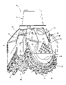
FIG. 1 is a perspective side view illustrating an example of an earth-boring
tool
to which hardfacing may be applied in accordance with embodiments of the
present
invention. The earth-boring tool of FIG. 1 is a rolling cutter type rotary
drill bit 10,
such bits also being known in the art as "roller cone" bits as noted above,
due to the
generally conical shape of the rolling cutters employed in many such bits. The
embodiment of the drill bit 10 shown in FIG. 1 includes three head sections 12
that are
welded together to form a bit body 14 of the drill bit 10, such an arrangement
being
well known to those of ordinary skill in the art. Only two of the head
sections 12 are
visible in FIG. 1. The bit body 14 may comprise a pin 22 or other means for
securing
the drill bit 10 to a drill string or bottom hole assembly (not shown). In
some
embodiments, the pin 22 may be configured to conform to industry standards for
threaded pin connections, such as those promulgated by the American Petroleum
Institute (API).
A bit leg 16 extends downwardly from each of the head sections 12 of the drill
bit 10. Each bit leg 16 may be integrally formed with the corresponding head
section 12 from which it depends. As shown in FIG. 1, at least one of
hardfacing
material 20 and inserts 21 may be used to protect the outer surfaces of the
bit legs 16
from wear. By way of example and not limitation, hardfacing material 20 may be
applied to the rotationally leading surfaces of the bit legs 16 and to the
lower surfaces
or "shirttails" at the lower end 18 of the bit legs 16, and inserts 21 may be
provided in
or on the radially outward most surfaces of the bit legs 16, as shown in FIG.
1. The
hardfacing material 20 and the inserts 21 may comprise materials that are
relatively
CA 02694432 2011-12-20
-8-
more wear-resistant relative to the material of the bit legs 16 at the
surfaces thereof. In
additional embodiments, the outer surfaces of the bit legs 16 may comprise
only inserts 21 and
no hardfacing material 20, or only hardfacing material 20 and no inserts 21.
In yet further
embodiments, the outer surfaces of the bit legs 16 may comprise neither
hardfacing material 20
nor inserts 21.
A rolling cutter in the form of a roller cone 40 may be rotatably mounted on a
bearing
shaft (not shown) that extends downwardly and radially inwardly from the lower
end 18 of each
bit leg 16 (relative to a longitudinal centerline (not shown) of the drill bit
10 and when the drill
bit 10 is oriented relative to the observer as shown in FIG. 1). The roller
cones 40 are rotatably
mounted on the bearing shafts such that, as the drill bit 10 is rotated at the
bottom of a wellbore
within an earth formation, the roller cones 40 roll and slide across the
underlying formation.
Each roller cone 40 includes a plurality of cutting elements 31, which may be
disposed
in rows extending circumferentially about the roller cone 40, for crushing and
scraping the
formation as the roller cones 40 roll and slide across the formation at the
bottom of the wellbore.
In the embodiment shown in FIG. 1, the cutting elements 31 comprise inserts
that are pressed
into complementary recesses formed in the body of the roller cones 40. The
inserts may
comprise a relatively hard and abrasive material such as, for example,
cemented tungsten
carbide. In additional embodiments, the cutting elements 31 may comprise
cutting teeth that are
machined on or in the surface of the roller cones 40. Such cutting teeth may
be coated with
hardfacing material (not shown), similar to the hardfacing material 20, which
may comprise, for
example, a composite material including hard particles (e.g., tungsten
carbide) dispersed within
a metal or metal alloy matrix material (e.g., an iron-based, cobalt-based, or
nickel-based alloy).
With continued reference to FIG. 1, the drill bit 10 includes three flow tubes
36 (only
two of which are visible in FIG. 1). In the embodiments shown in FIG. 1, the
flow tubes 36 are
discrete structures that are separately formed from the head sections 12 (and
integral bit legs 16)
of the drill bit 10. The flow tubes 36 are attached to the bit body 14 by, for
example, welding
the flow tubes 36 to the bit body 14 after welding the head sections 12
together to form the bit
body 14. In other embodiments, the flow tubes 36 may be welded to one or more
head sections
12 prior to welding the
CA 02694432 2010-02-23
-9-
head sections 12 together to form the bit body 14. In yet further embodiments,
the flow
tubes 36 may not be separately formed from the head sections 12 but, rather,
may be an
integral part of a head section 12.
The drill bit 10 includes internal fluid passageways (not shown in FIG. 1)
that
extend through the drill bit 10. The fluid passageways may each comprise, for
example, an internal longitudinal bore (not shown), which may also be termed a
plenum, that extends at least partially through the pin 22. The internal
longitudinal
bore may diverge into a plurality of relatively smaller passageways that lead
from the
longitudinal bore to the exterior of the drill bit 10. Some of these
passageways may
lead to, and extend through, the flow tubes 36.
As previously discussed, during drilling, drilling fluid is pumped from the
surface through the drill string (not shown) and the drill bit 10 to the
bottom of the
wellbore. The drilling fluid passes through the fluid passageways within the
drill bit 10
and out from the flow tubes 36 toward the cones and/or the exposed surfaces of
the
subterranean formation within the wellbore. Nozzles (not shown) may be
inserted
within each of the flow tubes 36. The nozzles may have internal geometries
designed,
sized and configured to at least partially define the velocity and the
direction of the
drilling fluid as the drilling fluid passes through the nozzles and exits the
flow tubes 36.
The present invention includes embodiments of methods of applying
hardfacing material to internal and external surfaces of earth-boring tools,
such as the
drill bit 10 shown in FIG. 1, to intermediate structures formed during such
methods,
and to earth-boring tools formed using such methods. Broadly, the methods
involve
mixing together a polymer material and particles that will ultimately be used
to form a
hardfacing material, applying the mixture to a surface of an earth-boring
tool, and
heating the mixture on the earth-boring tool to remove the polymer material
and sinter
the particles previously mixed therewith to form a layer of hardfacing
material on the
surface of the tool.
Referring to FIG. 2, a multi-layer film 30 may be formed and applied to
surfaces of an earth-boring tool such as, for example, to a bit body 14 of an
earth-boring rotary drill bit 10. For example, the multi-layer film 30 may be
applied to
inner surfaces of a bit body 14 within fluid passageways extending
therethrough to
fluid nozzles and, in particular, to regions of such inner surfaces that are
susceptible to
CA 02694432 2010-02-23
-10-
erosion caused by the flow of drilling fluid through the fluid passageways.
For
purposes of this application, regions "susceptible to erosion" caused by the
flow of
drilling fluid through the flow tube or fluid passageway may be considered as
those
regions of a flow tube, drill bit, or other earth-boring tool that will
eventually be eroded
away by drilling fluid when conventional drilling fluid is caused to flow
through the
flow tube or fluid passageway at conventional drilling flow rates and fluid
pressures for
a period of time of less than about five times the average lifetime, in terms
of operating
hours, for the respective design or model of the drill bit or other earth-
boring tool
carrying the flow tube or fluid passageway. In other words, if conventional
drilling
fluid is caused to flow through the flow tube or fluid passageway at
conventional flow
rates and fluid pressures for a period of time that is about five times the
average
lifetime of the respective design or model of the drill bit or other earth-
boring tool
carrying the flow tube or fluid passageway, and a region of the flow tube,
drill bit, or
other earth-boring tool has eroded away, that region may be considered to be a
region
"susceptible to erosion" caused by the flow of drilling fluid through the flow
tube or
fluid passageway for purposes of this application.
By way of example and not limitation, in some embodiments, the multi-layer
film 30 may comprise a flexible bilayered sheet as disclosed in U.S. Patent
No.
4,228,214 to Steigelman et al., which issued October 14, 1980.
As shown in FIG. 2, the multi-layer film 30 includes a first layer 32 and at
least
one additional second layer 34. The first layer 32 covers at least a portion
of a
surface 35 of the second layer 34. Each of the first layer 32 and the second
layer 34
includes a polymer material and a plurality of particles dispersed throughout
the
polymer material.
The polymer material of the first layer 32 may have a composition identical,
or
at least substantially similar to the polymer material of the second layer 34.
In
additional embodiments, the polymer material of the first layer 32 may have a
material
composition that is different from a material composition of the polymer
material of
the second layer 34. One or both of the polymer material of the first layer 32
and the
polymer material of the second layer 34 may comprise a thermoplastic and
elastomeric
material. As used herein, the term "thermoplastic material" means and includes
any
material that exhibits a hardness value that decreases as the temperature of
the material
CA 02694432 2010-02-23
-11-
is increased from about room temperature to about 93.3 C (200 F). As used
herein,
the term "elastic" means and includes a material that, when subjected to
tensile loading,
undergoes more non-permanent elongation deformation than permanent (i.e.,
plastic)
elongation deformation prior to rupture. By way of example and not limitation,
one or
both of the polymer of the first layer 32 and the polymer of the second layer
34 may
comprise at least one of styrene-butadiene-styrene, styrene-ethylene-butylene-
styrene,
styrene-divinylbenzene, styrene-isoprene-styrene, and styrene-ethylene-
styrene. The
thermoplastic elastomer may comprise a block co-polymer material having at
least one
end block having a molecular weight of between about 50,000 and about 150,000
grams per mole and at least one center block having a molecular weight of
between
about 5,000 and 25,000 grams per mole. Further, the block co-polymer material
may
exhibit a glass transition temperature between about 130 C and about 200 C. In
some
embodiments, at least one of the polymer material of the first layer 32 and
the polymer
material of the second layer 34 may be identical, or at least substantially
similar to,
those described in U.S. Patent 5,508,334, which issued April 16, 1996 to Chen.
With continued reference to FIG. 2, the particles within the first layer 32
may
be at least substantially comprised by hard particles. By way of example and
not
limitation, the particles within the first layer 32 may be at least
substantially comprised
of particles comprising a hard material such as diamond, cubic boron nitride
(the
foregoing two materials also being known in the art as "superhard" and
"superabrasive" materials), boron carbide, aluminum nitride, and carbides or
borides of
the group consisting of W, Ti, Mo, Nb, V, Hf, Zr, Si, Ta, and Cr.
The particles within the second layer 34 may be at least substantially
comprised
by particles comprising a metal or metal alloy for forming a matrix phase of
hardfacing
material. By way of example and not limitation, the particles within the
second
layer 34 may be at least substantially comprised of particles comprising
cobalt, a
cobalt-based alloy, iron, an iron-based alloy, nickel, a nickel-based alloy, a
cobalt- and
nickel-based alloy, an iron- and nickel-based alloy, an iron- and cobalt-based
alloy, an
aluminum-based alloy, a copper-based alloy, a magnesium-based alloy, or a
titanium-based alloy.
In additional embodiments, the particles within the first layer 32 may be at
least
substantially comprised of particles comprising a metal or metal alloy for
forming a
CA 02694432 2010-02-23
-12-
matrix phase of hardfacing material, and the particles within the second layer
34 may
be at least substantially comprised of hard particles. In yet further
embodiments, both
the first layer 32 and the second layer 34 may comprise hard particles and
particles
comprising a metal or metal alloy.
In some embodiments, one or both of the first layer 32 and the second layer 34
of the multi-layer film 30 may comprise a film of at least substantially solid
material.
For example, at least the second layer 34 may comprise a film of at least
substantially
solid material. Additionally, in some embodiments, one or both of the first
layer 32
and the second layer 34 of the multi-layer film 30 may comprise a paste. By
way of
example and not limitation, the second layer 34 may comprise a film of at
least
substantially solid material, and the first layer 32 may comprise a paste that
is disposed
on and at least substantially covers the surface 35 of the second layer 34, as
shown in
FIG. 2. FIG. 3 illustrates an additional embodiment of a multi-layer film 30'
of the
present invention that includes a first layer 32' and a second layer 34. The
multi-layer
film 30' is substantially similar to the multi-layer film 30 of FIG. 2, except
that the first
layer 32' of the multi-layer film 30' comprises a solid film, similar to that
of the second
layer 34.
FIG. 4 illustrates the multi-layer film 30 of FIG. 2 applied to a surface 15
of the
bit body 14 of the drill bit 10 to which it is desired to apply a hardfacing
material such
that the paste of the first layer 32 is disposed between the surface of the
earth-boring
tool and the second layer 34 of the multi-layer film 30. In other words, the
paste of the
first layer 32 may be disposed over at least a portion of a surface 15 of the
bit body 14
of the drill bit 10, and the second layer 34 may be disposed over at least a
portion of the
first layer 32 on a side thereof opposite the surface 15 of the body 14 of the
earth-boring rotary drill bit 10. The paste may be used to hold or adhere the
multi-layer
film 30 to the surface of the earth-boring tool until the earth-boring tool
and the
multi-layer film 30 are heated to form a hardfacing material from the multi-
layer
film 30, as described in further detail below. In some embodiments, the
surface 15 of
the body 14 of the earth-boring rotary drill bit 10 may comprise a surface 15
within a
fluid passageway 26 extending at least partly through the body 14 of the earth-
boring
rotary drill bit 10, as shown in FIG. 4.
CA 02694432 2010-02-23
-13-
FIG. 5 is a partial cross-sectional view of the portion of the bit body 14 of
the
earth-boring rotary drill bit 10 shown in FIG. 4, further illustrating a layer
of hardfacing
material 28 formed from a multi-layer film 30, 30' or paste, as previously
described
herein, on the surface 15 of the bit body 14 within a fluid passageway 26. By
way of
example and not limitation, the hardfacing material 28 may comprise a
composite
material having a relatively hard first phase distributed within a second,
continuous
metal or metal alloy matrix phase.
By way of example and not limitation, the first phase may comprise a hard
material such as diamond, boron carbide, cubic boron nitride, aluminum
nitride, and
carbides or borides of the group consisting of W, Ti, Mo, Nb, V, Hf, Zr, Si,
Ta, and Cr,
and the metal matrix phase may comprise cobalt, a cobalt-based alloy, iron, an
iron-based alloy, nickel, a nickel-based alloy, a cobalt- and nickel-based
alloy, an iron-
and nickel-based alloy, an iron- and cobalt-based alloy, an aluminum-based
alloy, a
copper-based alloy, a magnesium-based alloy, or a titanium-based alloy. In
some
embodiments, the first phase may comprise a plurality of discrete regions or
particles
dispersed within the metal or metal alloy matrix phase.
In some embodiments, the hardfacing material 28 may comprise a hardfacing
composition as described in U.S. Patent No. 6,248,149, which issued June 19,
2001
and is entitled "Hardfacing Composition for Earth-Boring Bits Using
Macrocrystalline
Tungsten Carbide and Spherical Cast Carbide," or in U.S. Patent No. 7,343,990,
which
issued March 18, 2008 and is entitled "Rotary Rock Bit With Hardfacing to
Reduce
Cone Erosion."
In some embodiments, the multi-layer films 30, 30' (FIGS. 2 and 3) used to
form the hardfacing material 28 may be formed in situ on the surface 15 (FIG.
4) of the
bit body 14 of the drill bit 10, while in other embodiments, the multi-layer
films 30, 30'
may be separately formed and subsequently applied to the surface 15. Methods
for
forming the multi-layer films 30 and 30' are described in further detail
below.
Particles that will be used to form hardfacing material 28 (FIG. 5) (i.e.,
hard
particles and/or particles comprising a metal or metal alloy matrix material)
may be
mixed with one or more polymer materials and one or more solvents to form a
paste or
slurry.
CA 02694432 2010-02-23
-14-
The one or more polymer materials may comprise a thermoplastic and
elastomeric polymer material, as previously mentioned. For example, at least
one of
styrene-butadiene-styrene, styrene-ethylene-butylene-styrene, styrene-
divinylbenzene,
styrene-isoprene-styrene, and styrene-ethylene-styrene may be mixed with the
particles
and the solvent to form the paste or slurry.
The slurry may comprise one or more plasticizers, in addition to the polymer
material, for selectively modifying the deformation behavior of the polymer
material.
The plasticizers may be, or include, light oils (such as paraffinic and
naphthenic
petroleum oils), polybutene, cyclobutene, polyethylene (e.g., polyethylene
glycol),
polypropene, an ester of a fatty acid or an amide of a fatty acid.
The solvent may comprise any substance in which the polymer material can at
least partially dissolve. For example, the solvent may comprise methyl ethyl
ketone,
alcohols, toluene, hexane, heptane, propyl acetate, and trichloroethylene, or
any other
conventional solvent.
The slurry also may comprise one or more stabilizers for aiding suspension of
the one or more polymer materials in the solvent. Suitable stabilizers for
various
combinations of polymers and solvents are known to those of ordinary skill in
the art.
After forming the paste or slurry, the paste or slurry may be applied as a
relatively thin layer on a surface of a substrate using, for example, a tape
casting
process. The solvent then may be allowed to evaporate from the paste or slurry
to form
a relatively solid layer of polymer material in which the hard particles
and/or particles
comprising a metal or metal alloy matrix material are embedded. For example,
the
paste or slurry may be heated on a substantially planar surface of a drying
substrate
after tape casting to a temperature sufficient to evaporate the solvent from
the paste or
slurry. The paste or slurry may be dried under a vacuum to decrease drying
time and to
eliminate any vapors produced during the drying process.
To form the multi-layer film 30 shown in FIG. 2, a slurry may be formed by
mixing particles comprising a metal or metal alloy matrix material with one or
more
polymer materials and one or more solvents, and the slurry may be tape cast
and dried
to form the second layer 34 of the multi-layer film 30. After forming the
second
layer 34, a paste may be formed by mixing hard particles with one or more
polymer
materials and one or more solvents, and the paste may be applied to a major
surface of
CA 02694432 2010-02-23
- 15-
the second layer 34 such that the major surface of the second layer 34 is at
least
substantially coated with the paste to form the first layer 32 of the multi-
layer film 30.
To form the multi-layer film 30' shown in FIG. 3, a first slurry may be formed
by mixing particles comprising a metal or metal alloy matrix material with one
or more
polymer materials and one or more solvents, and the first slurry may be tape
cast and
dried to form the second layer 34 of the multi-layer film 30', as previously
discussed.
After forming the second layer 34, a second slurry may be formed by mixing
hard
particles with one or more polymer materials and one or more solvents, and the
second
slurry may be tape casted and dried over a major surface of the second layer
34 to form
the first layer 32 of the multi-layer film 30'. In other embodiments, the
first layer 32'
and the second layer 34 may be separately formed in separate tape casting and
drying
processes and subsequently laminated together to form the multi-layer film 30'
by, for
example, placing the first layer 32' and the second layer 34 adjacent one
another and
passing them together between pressure rollers.
In additional embodiments, a paste formed by mixing hard particles and
particles comprising a metal or metal alloy matrix material with one or more
polymer
materials and one or more solvents (and, optionally, plasticizers, etc.) may
be applied
directly to the surface 15 of the bit body 14 of the drill bit 10 to which
hardfacing
material 28 (FIG. 5) is to be applied, and hardfacing material 28 may be
formed from
the paste as subsequently described herein.
After forming the multi-layer film 30, 30', the multi-layer film 30, 30' may
be
applied to the surface 15 of the bit body 14 of the drill bit 10 to which
hardfacing
material 28 is to be applied (if the multi-layer film 30, 30' was not formed
in situ on the
surface 15 of the body 14). If the multi-layer film 30, 30' will not stick to
the
surface 15 of the body 14 by itself, an adhesive may be provided between the
multi-layer film 30, 30' and the surface 15 of the body 14 to adhere the multi-
layer
film 30, 30' to the surface 15 of the body 14. The multi-layer film 30, 30'
may be cut
or otherwise formed to have a desired shape complementary to a surface 15 to
which it
is to be applied. For example, the multi-layer film 30, 30' may be cut or
otherwise
formed to have a shape complementary to an inner surface of an earth-boring
tool
within a fluid passageway extending therethrough.
CA 02694432 2010-02-23
-16-
The body 14 of the earth-boring rotary drill bit 10, together with the multi-
layer
film 30, 30' or paste on one or more surfaces 15 thereof, then may be heated
in a
furnace to form a hardfacing material 28 on the surface 15 of the body 14 from
the
multi-layer film 30, 30' or paste. Upon heating the multi-layer film 30, 30'
or paste to
temperatures of between about 150 C and about 500 C, organic materials within
the
multi-layer film 30, 30' or paste may volatize and/or decompose, leaving
behind the
inorganic components of the multi-layer film 30, 30' or paste on the surface
15 of the
body 14. For example, the multi-layer film 30, 30' or paste may be heated at a
rate of
about 2 C per minute to a temperature of about 450 C to cause organic
materials
(including polymer materials) within the multi-layer film 30, 30' or paste to
volatilize
and/or decompose.
After heating the multi-layer film 30, 30' or paste to volatilize and/or
decompose organic materials therein, the remaining inorganic materials of the
multi-layer film 30, 30' or paste may be further heated to a relatively higher
sintering
temperature to sinter the inorganic components and form a hardfacing material
28
therefrom. For example, the remaining inorganic materials of the multi-layer
film 30,
30' or paste may be further heated at a rate of about 15 C per minute to a
sintering
temperature of about 1150 C. The sintering temperature may be proximate a
melting
temperature of the metal or metal alloy matrix material of the matrix
particles in the
multi-layer film 30, 30' or paste. For example, the sintering temperature may
be
slightly below, slightly above, or equal to a melting temperature of the metal
or metal
alloy matrix material.
The volatilization and/or decomposition process, as well as the sintering
process, may be carried out under vacuum (i. e., in a vacuum furnace), in an
inert
atmosphere (e.g., nitrogen, argon, helium, or another at least substantially
inert gas), or
in a reducing atmosphere (e.g., hydrogen).
During the sintering process, at least the particles comprising a metal or
metal
alloy may condense and coalesce to form an at least substantially continuous
metal or
metal alloy matrix phase in which a discontinuous hard phase formed from the
hard
particles is distributed. In other words, during sintering, the hard particles
may become
embedded within a layer of metal or metal alloy matrix material formed from
the
particles comprising the metal or metal alloy matrix material. During the
sintering
CA 02694432 2010-02-23
-17-
process, the metal or metal alloy matrix material within the second layer 34
of the
multi-layer film 30, 30' may be wicked into the first layer 32, 32' between
the hard
particles therein. As the body 14 of the earth-boring rotary drill bit 10 is
cooled, the
metal or metal alloy matrix material bonds to the surface 15 of the body 14
and holds
the hard particles in place on the surface 15 of the body 14.
In some embodiments, the multi-layer film 30, 30' or paste may have an
average thickness and composition such that, upon sintering, the resulting
layer of
hardfacing material 28 formed on the surface 15 of the body 14 of an earth-
boring tool
has an average thickness of between about 1.25 millimeters (0.05 inch) and
about 12
millimeters (0.5 inch).
As previously mentioned, embodiments of methods of the present invention
may be used to apply hardfacing materials to surfaces of earth-boring tools
within fluid
passageways extending at least partly therethrough. Such fluid passageways may
extend, for example, through a bit body of an earth-boring rotary drill bit
and/or
through a flow tube on a bit body of an earth-boring rotary drill bit. FIGS.
6A-6F
illustrate an example of a flow tube 36 to which hardfacing material 28 may be
applied
in accordance with embodiments of the present invention. FIG. 6A is an
isometric
view of the flow tube 36, FIG. 6B is a side view of the flow tube 36, and FIG.
6C is a
front view of the flow tube 36.
Referring to FIG. 6A, the flow tube 36 includes a tube body 38, which may
comprise a metal or metal alloy such as, for example, steel. As shown in FIG.
6D,
which is a longitudinal cross-sectional view of the flow tube 36 taken along
section
line 6D-6D shown in FIG. 6C, a fluid passageway 26 extends through the tube
body 38
of the flow tube 36 from an inlet 42 to an outlet 44. Drilling fluid flows
through the
fluid passageway 26 from the inlet 42 to the outlet 44 during drilling.
Annular
recesses 48 or other geometric features (e.g., threads) may be machined or
otherwise
provided in the inner walls 39 of the tube body 38 within the fluid passageway
26
proximate the outlet 44 to receive and secure a nozzle and any associated
seals (e.g.,
o-rings) and retention rings therein.
Referring again to FIG. 6A, hardfacing material 28 may be applied to one or
both of the rotationally leading outer edge 50 and the rotationally trailing
outer edge 52
of the tube body 38. Furthermore, hardfacing material 28 may be applied to
exterior
CA 02694432 2010-02-23
-18-
surfaces of the tube body 38 of the flow tube 36 over regions that are
proximate to, or
adjacent, regions of the inner walls 39 (FIG. 6D) of the tube body 38 that are
susceptible to erosion caused by the flow of drilling fluid through the flow
tube 36.
Referring to FIG. 6D, a first section 41A of the fluid passageway 26 extends
through the flow tube 36 in a first direction from the inlet 42 in a radially
outward and
downward direction (relative to a longitudinal centerline of the drill bit 10
when the
flow tube 36 is secured to the drill bit 10 and the drill bit 10 is oriented
relative to the
observer as shown in FIG. 1). The first section 41 A of the fluid passageway
26
transitions to a second section 41B of the fluid passageway 26 that extends in
a
generally downward direction to the outlet 44. In the embodiment shown in
FIGS. 6A-6E, the first section 41A of the fluid passageway 26 is oriented at
an obtuse
angle (i.e., between 90 and 180 ) relative to the second section 41 B of the
fluid
passageway 26. In this configuration, as drilling fluid passes from the first
section 41A
into the second section 41B of the fluid passageway 26, the drilling fluid may
impinge
on the radially outward regions of the inner walls 39 of the tube body 38
within the
second section 41 B at an acute angle of less than ninety degrees (90 ). As a
result, the
radially outward regions of the inner walls 39 of the tube body 38 within the
second
section 41 B of the fluid passageway 26 may be more susceptible to erosion
caused by
the passage of drilling fluid through the fluid passageway 26 relative to
other regions of
the inner walls 39 of the tube body 38.
To reduce damage to the flow tube 36 caused by such erosion, a relatively
thick
layer of hardfacing material 28' may be applied to the regions of the outer
surfaces of
the tube body 38 of the flow tube 36 that are adjacent the regions of the
inner walls 39
of the tube body 38 that are susceptible to erosion, as shown in FIGS. 6A-6E.
The
relatively thick layer of hardfacing material 28' may be configured in the
form of an
elongated strip extending down and covering the radially outermost regions of
the outer
surfaces of the tube body 38 of the flow tube 36 (relative to the longitudinal
centerline
of the drill bit 10 (FIG. 1)), as best shown in FIGS. 6A and 6C.
In using the hardfacing material 28'to reduce damage to the flow tube 36
caused by erosion of the inner walls 39 of the tube body 38, it may be
desirable to
configure the relatively thick layer of hardfacing material 28' to have a
thickness that is
greater than a thickness of hardfacing material 28 used to prevent or reduce
abrasive
CA 02694432 2010-02-23
-19-
wear to exterior surfaces of the flow tube 36, such as the hardfacing material
28 applied
to the rotationally leading and trailing outer edges 50, 52 of the flow tube
36. By way
of example and not limitation, the relatively thick layer of hardfacing
material 28 may
have an average thickness of greater than about 5.0 millimeters (greater than
about 0.2
inch), and the hardfacing material 28 applied to the rotationally leading and
trailing
outer edges 50, 52 of the flow tube 36 may have an average thickness of less
than about
4.5 millimeters (less than about 0.18 inch). As one particular non-limiting
example, the
relatively thick layer of hardfacing material 28' may have an average
thickness of
between about 6.9 millimeters (about 0.27 inch) and about 8.2 millimeters
(about 0.32
inch), and the hardfacing material 28 applied to the rotationally leading and
trailing
outer edges 50, 52 of the flow tube 36 may have an average thickness of
between about
0.8 millimeters (about 0.03 inch) and about 1.6 millimeters (about 0.06 inch).
In some embodiments, it may be desirable to configure the exterior surface of
the relatively thick layer of hardfacing material 28' and the exterior
surfaces of the
hardfacing material 28 applied to the rotationally leading and trailing outer
edges 50,
52 of the flow tube 36 to be substantially flush with one another, as shown in
FIG. 6A.
To enable the exterior surface of the hardfacing material 28' and the
hardfacing
material 28 to be substantially flush with one another, the layer of
hardfacing
material 28' may be at least partially disposed within a recess 56 provided in
an outer
surface of the tube body 38 of the flow tube, as shown in FIGS. 6A, 6C, 6D,
and 6E.
Referring to FIGS. 6D and 6E, in some embodiments, the recess 56 may be
configured
as a groove that extends in a downward direction along the outer surface of
the tube
body 38. As one non-limiting example, the recess 56 may extend into the outer
surface
of the tube body 38 to a depth of between about 5.0 millimeters (about 0.20
inch) and
about 13.0 millimeters (about 0.50 inch). More particularly, the recess 56 may
extend
into the outer surface of the tube body 38 to a depth of between about 6.1
millimeters
(about 0.24 inch) and about 6.6 millimeters (about 0.26 inch).
FIG. 6F is a longitudinal cross-sectional view of the flow tube 36, like that
of
FIG. 6D, illustrating erosion of the inner walls 39 of the tube body 38 of the
flow
tube 36 that may occur after causing drilling fluid to flow through the flow
tube 36 for
a period of time during drilling. As shown in FIG. 6F, the inner walls 39 of
the tube
body 38 within the fluid passageway 26 may erode until the relatively thick
layer of
CA 02694432 2010-02-23
-20-
hardfacing material 28 is exposed within the fluid passageway 26. The
hardfacing
material 28' may wear due to erosion at a rate that is lower than the rate at
which the
material of the tube body 38 of the flow tube 36 wears due to erosion.
Therefore, the
hardfacing material 28' may prevent the drilling fluid from eroding entirely
through the
walls of the flow tube 36 from the interior fluid passageway 26 as quickly as
in
previously known flow tubes, thereby allowing embodiments of flow tubes 36 of
the
present invention to properly function for longer periods of time and through
the
operational life of the drill bit 10.
In some embodiments, the hardfacing material 28 and the hardfacing
material 28' may have identical or similar compositions. In other embodiments,
however, the material composition of the hardfacing material 28 may differ
from the
material composition of the hardfacing material 28'. For example, in the
embodiment
described above with reference to FIGS. 6A-6F, the hardfacing material 28
applied to
the rotationally leading and trailing outer edges 50, 52 of the flow tube 36
may be
intended primarily to reduce wear caused by abrasion, while at least a portion
of the
hardfacing material 28' may be intended primarily to reduce wear caused by
erosion.
Abrasion and erosion are two different wear mechanisms, and some material
compositions have better resistance to abrasive wear, while other material
compositions have better resistance to erosive wear. Therefore, the hardfacing
material 28' may have a material composition that exhibits increased erosion
resistance
relative to the hardfacing material 28, while the hardfacing material 28 may
have a
material composition that exhibits increased abrasion resistance relative to
the
hardfacing material 28'in some embodiments of the present invention.
Referring to FIG. 6E, in some embodiments, the relatively thick layer of
hardfacing material 28' optionally may comprise a multilayer structure having
different
layers that exhibit one or more differing physical properties. By way of
example and
not limitation, the relatively thick layer of hardfacing material 28' may
comprise a
radially inward first layer 28A' having a material composition tailored to
exhibit
enhanced resistance to erosion, and a radially outward second layer 28B'
having a
material composition tailored to exhibit enhanced resistance to abrasion. In
other
words, the first layer 28A' may exhibit an erosion resistance that is greater
than an
erosion resistance exhibited by the second layer 28B', and the second layer
28B' may
CA 02694432 2010-02-23
-21-
exhibit an abrasion resistance that is greater than an abrasion resistance
that is exhibited
by the first layer 28A'. As one particular non-limiting example, the first
layer 28A' of
the hardfacing material 28' may substantially fill the recess 56 formed in the
outer
surface of the tube body 38 of the flow tube 36, and the second layer 28B' of
the
hardfacing material 28' may have a material composition identical to that of
the
hardfacing material 28 applied to the rotationally leading and trailing outer
edges 50,
52 of the flow tube 36. Furthermore, the second layer 28B' of the hardfacing
material 28' may be integrally formed with the hardfacing material 28 applied
to the
rotationally leading and trailing outer edges 50, 52 of the flow tube 36.
FIGS. 7A-7D illustrate another example embodiment of a flow tube 66 having
surfaces to which a hardfacing material may be applied in accordance with
embodiments of the present invention. FIG. 7A is an isometric view of the flow
tube 66 and FIG. 7B is a front view of the flow tube 66. FIG. 7C is a
longitudinal
cross-sectional view of the flow tube 66 taken along section line 7C-7C of
FIG. 7B,
and FIG. 7D is a transverse cross-sectional view of the flow tube 66 taken
along
section line 7D-7D of FIG. 7B.
Referring to FIG. 7A, the flow tube 66 includes a tube body 68 that is
generally
similar to the previously described tube body 38 of the flow tube 36 shown in
FIG. 6A,
and includes a fluid passageway 26 that extends through the tube body 68 of
the flow
tube 66 from an inlet 42 to an outlet 44 (FIG. 7C). Furthermore, hardfacing
material 28 may be applied to rotationally leading and trailing outer edges
72, 74 of the
flow tube 66. The tube body 68 of the flow tube 66, however, may not include a
recess 56 (FIG. 6A), and the flow tube 66 may include a plurality of wear-
resistant
inserts 70 instead of a relatively thick layer of hardfacing material 28', as
previously
described with reference to the flow tube 36. The wear-resistant inserts 70
may be
effective at reducing abrasive wear to the outer surface of the tube body 68
of the flow
tube 66. The wear-resistant inserts 70, however, may be relatively less
effective
(relative to the previously described layer of hardfacing material 28' (FIG.
6D) at
reducing erosive wear to the tube body 68 caused by the flow of drilling fluid
through
the fluid passageway 26.
Referring to FIG. 7C, a hardfacing material 28 may be applied to at least a
portion of the inner walls 80 of the tube body 68 within the fluid passageway
26. The
CA 02694432 2010-02-23
-22-
hardfacing material 28 may be used to reduce erosive wear to the tube body 68
caused
by the flow of drilling fluid through the fluid passageway 26. In some
embodiments,
the hardfacing material 28 may be applied to and cover substantially all of
the inner
walls 80 of the tube body 68 of the flow tube 66 that are exposed within the
fluid
passageway 26 after securing a nozzle (not shown) therein. In other
embodiments, the
hardfacing material 28 may be applied only to regions of the inner walls 80
that are
susceptible to erosion, such as the regions of the inner walls 80 at which
drilling fluid
will impinge on the inner walls 80 at acute angles as drilling fluid is pumped
through
the flow tube 66.
By way of example and not limitation, the layer of hardfacing material 28
applied to the inner walls 80 of the tube body 68 may have an average
thickness of
between about 1.25 millimeters (0.05 inch) and about 20 millimeters (0.8
inch). The
hardfacing material 28 may have a material composition tailored to exhibit
enhanced
erosion resistance.
In additional embodiments of the invention, flow tubes may be provided that
include both a relatively thick layer of hardfacing material 28' as previously
disclosed
in relation to FIGS. 6A-6F and a hardfacing material 28 applied to at least a
portion of
an inner wall of a body within a fluid passageway, as previously disclosed in
relation to
FIGS. 7A-7D.
Although the flow tube 36 previously described in relation to FIGS. 6A-6F and
the flow tube 66 previously described in relation to FIGS. 7A-7D are
illustrated as
comprising separate bodies that are attached to a bit body (or one bit leg or
bit head
section of a bit body) by, for example, welding, additional embodiments of the
present
invention may comprise flow tubes that are integrally formed with (and are an
integral
portion of) a bit body (or one bit leg or a bit head section of a bit body),
as well as
earth-boring tools having such integrally formed flow tubes or fluid
passageways.
Additional example embodiments are described below.
Embodiment 1: A multi-layer film for use in forming a layer of hardfacing on
a surface of a tool, comprising: a first layer comprising: a first polymer
material; and a
first plurality of particles dispersed throughout the first polymer material;
and a second
layer covering at least a portion of a surface of the first layer, the second
layer
CA 02694432 2010-02-23
-23-
comprising: a second polymer material; and a second plurality of particles
dispersed
throughout the second polymer material.
Embodiment 2: The multi-layer film of Embodiment 1, wherein the first
polymer material and the second polymer material have at least substantially
similar
compositions.
Embodiment 3: The multi-layer film of Embodiment 1, wherein at least one of
the first polymer material and the second polymer material comprises a
thermoplastic
and elastomeric material.
Embodiment 4: The multi-layer film of Embodiment 1 or Embodiment 2,
wherein at least one of the first polymer material and the second polymer
material
comprises at least one of styrene-butadiene-styrene, styrene-ethylene-butylene-
styrene,
styrene-divinylbenzene, styrene-isoprene-styrene, and styrene-ethylene-
styrene.
Embodiment 5: The multi-layer film of any one of Embodiments 1 through 4,
wherein at least one of the first polymer material and the second polymer
material
further comprises at least one of an oil, polybutene, cyclobutene,
polyethylene,
polyethylene glycol, and polypropene.
Embodiment 6: The multi-layer film of any of Embodiments 1 through 5
wherein the first plurality of particles is at least substantially comprised
of hard
particles.
Embodiment 7: The multi-layer film of Embodiments 1 through 6, wherein the
second plurality of particles is at least substantially comprised of particles
comprising a
metal or metal alloy.
Embodiment 8: The multi-layer film of any one of Embodiments 1 through 7,
wherein at least one of the first polymer material and the second polymer
material
comprises a thermoplastic and elastomeric material.
Embodiment 9: The multi-layer film of any one of Embodiments 1 through 8,
wherein at least one of the first layer and the second layer comprises a film
of at least
substantially solid material.
Embodiment 10: The multi-layer film of any one of Embodiments 1 through 9,
wherein one of the first layer and the second layer comprises a paste.
Embodiment 11: An intermediate structure formed during fabrication of an
earth-boring tool, comprising: a body of an earth-boring tool; a first
material layer
CA 02694432 2010-02-23
-24-
disposed over at least a portion of a surface of the body, the first film
comprising: a
first polymer material; and a plurality of hard particles dispersed throughout
the first
polymer material; and a second material layer disposed over at least a portion
of the
first material layer on a side thereof opposite the body, the second material
layer
comprising: a second polymer material; and a plurality of metallic matrix
particles
dispersed throughout the second polymer material.
Embodiment 12: The intermediate structure of Embodiment 11, wherein each
of the first material layer and the second material layer comprises a film of
solid
material.
Embodiment 13: The intermediate structure of Embodiment 11, wherein the
first material layer comprises a layer of paste, and the second material layer
comprises
a film of solid material.
Embodiment 14: The intermediate structure of any one of Embodiments 11
through 13, wherein the at least a portion of the surface of the body
comprises a surface
of a body of an earth-boring rotary drill bit within a fluid passageway
extending at least
partially through the body of the earth-boring rotary drill bit.
Embodiment 15: A method of applying hardfacing to a surface of an
earth-boring tool, comprising: mixing a plurality of hard particles, a
plurality of metal
matrix particles, a polymer material, and a liquid solvent to form a paste;
spreading the
paste over a surface of a substrate to form a layer of the paste; removing the
liquid
solvent from the layer of the paste to form an at least substantially solid
film
comprising the plurality of hard particles, the plurality of metal matrix
particles, and
the polymer material; removing the at least substantially solid film from the
surface of
the substrate; applying the at least substantially solid film to a surface of
a body of an
earth-boring tool; heating the body of the earth-boring tool to a first
temperature while
the at least substantially solid film is on the surface thereof and removing
the polymer
material from the body of the earth-boring tool; and heating the body of the
earth-boring tool to a second temperature higher than the first temperature
and sintering
at least the plurality of metal matrix particles to form a layer of hardfacing
material on
the surface of the body of the earth-boring tool comprising the plurality of
hard
particles dispersed throughout a metal matrix phase formed from the plurality
of metal
matrix particles.
CA 02694432 2010-02-23
-25-
Embodiment 16: The method of Embodiment 15, wherein applying the at least
substantially solid film to a surface of a body of an earth-boring tool
comprises
applying the at least substantially solid film to a surface of a body of an
earth-boring
rotary drill bit within a fluid passageway extending at least partially
through the body
of the earth-boring rotary drill bit.
Embodiment 17: The method of Embodiment 15 or Embodiment 16, further
comprising selecting the polymer material to comprise a thermoplastic and
elastomeric
material.
Embodiment 18: The method of Embodiment 17, further comprising selecting
the polymer material to comprise at least one of styrene-butadiene-styrene,
styrene-ethylene-butylene-styrene, styrene-divinylbenzene, styrene-isoprene-
styrene,
and styrene-ethylene-styrene.
Embodiment 19: The method of Embodiment 17 or Embodiment 18, further
comprising selecting the polymer material to comprise at least one of an oil,
polybutene, cyclobutene, polyethylene, polyethylene glycol, and polypropene.
Embodiment 20: A method of applying hardfacing to a surface of an
earth-boring tool, comprising: providing a first material layer comprising a
plurality of
hard particles and a first polymer material on a surface of a body of an earth-
boring
tool; providing a second material layer comprising a plurality of metal matrix
particles
and a second polymer material adjacent the first material layer on a side
thereof
opposite the body of the earth-boring tool; heating the body of the earth-
boring tool to a
first temperature while the first material layer and the second material layer
are on the
body of the earth-boring tool and removing the first polymer material and the
second
polymer material from the body of the earth-boring tool; and heating the body
of the
earth-boring tool to a second temperature higher than the first temperature
and sintering
at least the plurality of metal matrix particles to form a layer of hardfacing
material on
the surface of the body of the earth-boring tool comprising the plurality of
hard
particles dispersed throughout a metal matrix phase formed from the plurality
of metal
matrix particles.
Embodiment 21: The method of Embodiment 20, further comprising forming
the second material layer to comprise an at least substantially solid film
comprising the
CA 02694432 2011-12-20
-26-
second polymer material and the metal matrix particles dispersed throughout
the second polymer
material.
Embodiment 22: The method of Embodiment 20 or Embodiment 21, further
comprising
forming the first material layer to comprise a paste including the plurality
of hard particles, the
first polymer material, and a liquid solvent.
Embodiment 23: The method of Embodiment 21, further comprising: covering a
surface
of the at least substantially solid film with the paste; and applying the at
least substantially solid
film to the surface of the body of the earth-boring tool with the paste
disposed between the
surface and the at least substantially solid film.
Embodiment 24: The method of any one of Embodiments 20 through 23, further
comprising selecting the surface of the body of the earth-boring tool to
comprise a surface of a
body of an earth-boring rotary drill bit within a fluid passageway extending
at least partially
through the body of the earth-boring rotary drill bit.
Embodiment 25: The method of any one of Embodiments 20 through 24, further
comprising selecting at least one of the first polymer material and the second
polymer material
to comprise a thermoplastic and elastomeric material.
Embodiment 26: The method of any one of Embodiments 20 through 25, further
comprising selecting the first polymer material and the second polymer
material to have at least
substantially similar material compositions.
While the present invention has been described herein with respect to certain
illustrated
embodiments, those of ordinary skill in the art will recognize and appreciate
that it is not so
limited. The scope of the claims should not be limited by the preferred
embodiments set forth in
the examples, but should be given the broadest interpretation consistent with
the description as a
whole. Further, the invention has utility with different and various bit
profiles as well as cutting
element types and configurations.