Note : Les descriptions sont présentées dans la langue officielle dans laquelle elles ont été soumises.
CA 02695079 2010-03-01
TAMPER EVIDENT CONTAINER WITH PULL TAB
BACKGROUND OF THE INVENTION
Field of the Invention
[0001] The present invention generally relates to a container with a pull tab
having a
deformable formation, a tamper evident feature for a container, and a method
for forming a
container. Embodiments of the invention relate to containers with a pull tab
that can be used in
the food industry for storing, transporting, and showing foodstuffs.
Description of Related Art
[0002] Conventionally, there are many different types of containers used in
the food
industry for storing, transporting and showing foodstuffs on the shelves in
shops and markets.
One problem prevalent in supermarkets is that customers will occasionally
attempt to obtain
access to the contents of food containers to taste or examine the foods. This
is clearly
undesirable since this action could cause contamination of the foodstuffs and
furthermore, other
customers do not wish to buy the affected products. Several tamper-evident
containers have
been devised to address this problem.
[0003] U.S. Patent Nos. 5,145,088 and 5,507,406 disclose known solutions, but
it has
been found that these and other conventional tamper-evident containers have
various drawbacks
in terms of cost and manufacture, and also that significant proportions of
important parts of the
container and/or cover are destroyed when the cover is opened for the first
time.
NY02:635808.8
1
CA 02695079 2010-03-01
SUMMARY OF THE INVENTION
[0004] The purpose and advantages of the present invention will be set forth
in and
apparent from the description that follows, as well as will be learned by
practice of the invention.
Additional advantages of the invention will be realized and attained by the
apparatus and
methods particularly pointed out in the written description and claims hereof,
as well as from the
appended drawings.
[0005] To achieve these and other advantages and in accordance with the
purpose of the
invention, as embodied and broadly described, the invention includes a
container with a pull tab
having a deformable formation. The container can be used to store, transport,
and show
foodstuffs, as well as any other suitable applications.
[0006] The container includes a base, a cover, and a pull tab. The base can
include, but
is not limited to, a bottom, a side wall extending upwardly from the bottom,
and a rim at an
upper edge portion of the sidewall. The cover has a closed condition and an
open condition. The
cover can include, but is not limited to, an outer edge portion
interengageable with the rim of the
base when the cover is in the closed condition. The pull tab extends outwardly
from at least one
of the base or the cover.
[0007] In accordance with one aspect of the invention, the pull tab has a
deformable
formation to be deformed when the cover is moved from a closed condition to an
open condition.
Furthermore, the pull tab is configured to remain attached to the at least one
of the base or the
cover when moved from the closed condition to the open condition. The
deformable formation
can include a plurality of recesses or protrusions defined on the surface of
the pull tab. Further,
the deformable formation can be configured to create an audible or visible
indication upon
NY02:635808.8
-2-
CA 02695079 2010-03-01
application of sufficient force to the pull tab to disengage the outer edge
portion of the cover
from the rim of the base.
[0008] In accordance with another aspect of the invention, the outer edge
portion of the
cover and the rim of the base are interengageable when the cover is in the
closed position. In a
preferred embodiment, the outer edge portion of the cover or the rim of the
base includes a
channel to receive the other of the outer edge portion of the cover or the rim
of the base for
interengagement therebetween. The channel can have a cross-section
configuration that
corresponds to the other of the outer edge portion of the cover or the rim for
mating
interengagement therebetween.
[0009] The base can include a ramp aligned with the pull tab when the cover is
closed.
The pull tab can be angled relative to the outer edge portion of the cover by
the ramp. In some
embodiments, the base includes a textured area, which can define a grip area
for the pull tab.
[0010] It is to be understood that both the foregoing general description and
the
following detailed description are exemplary and are intended to provide
further explanation of
the invention claimed.
[0011] The accompanying drawings, which are incorporated in and constitute
part of this
specification, are included to illustrate and provide a further understanding
of the apparatus and
method of the invention. Together with the written description, the drawings
serve to explain the
principles of the invention.
BRIEF DESCRIPTION OF THE DRAWINGS
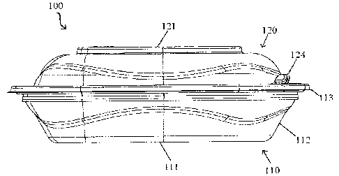
[0012] FIG. I is side view of a representative embodiment of a container in
accordance
with the invention.
NY02:635808.5
-3-
CA 02695079 2010-03-01
[0013] FIG. 2 is a cross-sectional side view along a mid-line of the container
shown in
FIG. 1,
[0014] FIG. 3 is a top view of the container shown in FIG. 1,
[0015] FIG. 4 is an enlarged cross-sectional side view of the rim area of the
container of
FIG. 2.
[0016] FIG. 5 is an enlarged view of the pull tab area of the base and cover
shown in
FIG. 3.
[0017] FIG. 6 is an enlarged view of the pull tab of the cover shown in FIG. 3
prior to
assembly to the base.
[0018] FIG. 7 is an enlarged side view of the ramp area shown in FIG. 5.
[0019] FIG. 8 is a top view of another representative embodiment of a cover of
a
container in accordance with the invention.
[0020] FIG. 9 is a top view of another representative embodiment of a base of
a container
in accordance with the invention.
DETAILED DESCRIPTION OF THE PREFERRED :El1mODIMENT
[0021] Reference will now be made in detail to the present preferred
embodiments of the
invention, an example of which is illustrated in the accompanying drawings.
The method and
corresponding steps of the invention will be described in conjunction with the
detailed
description of the apparatus.
[0022] The apparatus and methods presented herein generally are intended for
any two
piece or hinged containers for storing, transporting, and showing foodstuffs,
although other
similar or suitable uses'are contemplated. One aspect of the invention is
particularly suited for
containers requiring a method of illustrating tampering when opened. In
accordance with the
NY02:63$*08.9
-4-
CA 02695079 2010-03-01
invention, a container having a base, a cover, and a pull tab having a
deformable formation is
provided. The base has a bottom, a side wall extending upwardly from the
bottom, and a rim at
an upper edge portion of the side wall. The cover has a closed condition and
an open condition.
The cover has an outer edge portion interengageable with the rim of the base
when the cover is in
the closed condition. The pull tab extends outwardly from at least one of the
base or the cover.
The pull tab has a deformable formation to be deformed when the cover is moved
from the
closed condition to the open condition. Furthermore, the pull tab is
configured to remain
attached to the at least one of the base or the cover when moved from the
closed condition to the
open condition.
[00231 For purpose of explanation and illustration, and not limitation, an
exemplary
embodiment of the container in accordance with the invention is shown in Figs.
1, 2, and 3 and is
designated generally by reference character 100.
[0024] Figures 1 and 2 show a first embodiment of a container 100 in
accordance with
the invention. The container includes abase 110 having a bottom 111, a side
wall 112
extending upwardly from the bottom, and a rim 113 at an upper edge portion of
the side wall. In
some embodiments, the base is generally bowl-shaped with a flat bottom.
Alternatively, the
bottom may have a raised center portion 114 such as shown in Figure 2.: The
rim 113 extends
radially outward from the upper edge portion of the side wall in generally a
horizontal plane.
[0025] The container also includes a cover 120 having an outer edge portion
123 (not
shown in Figure 1=) corresponding to the rim of the base. For purpose of
illustration, the cover
includes a pull tab 124 extending outwardly from the outer edge portion at a
region of the
periphery of the cover. The pull tab 124 has a deformable formation 125 (shown
in Figure 3) to
be deformed when the cover is moved from a closed condition to an open
condition. Although
NY02:635808.8
-5-
CA 02695079 2010-03-01
the base 110 and cover 120 are shown in Figures 1 and 2 as separate pieces,
alternatively, the
base and the cover can be hingedly connected using a variety of known
techniques, as further
described in International Publication No,. WO 2005/082734, filed February 24,
2005, the entire
disclosure of which is hereby incorporated by reference. Similarly, the pull
tab can be
configured to extend from the base, or if desired, a pull tab can extend from
the cover and the
base, respectively.
[0026] The container is made of suitable material having slight resilience and
is
particularly useful for holding foodstuffs such as fruit, vegetables and
prepared foods such as
salads, etc. Preferably, the cover is made of a clear plastics material so the
foodstuff therein is
visible to a consumer. The container can be rectangular, round or any other
desired shape.
Examples of materials include polystyrene, polypropylene, polyethylene
terephthalate (PET),
and other suitable materials.
[0027] Generally, the pull tab has a deformable formation to be deformed when
the
container is moved from the closed condition to the open condition. For
example, and with
reference to the embodiment of Figure t herein, the deformable formation 125
includes a
plurality of recesses defined on a surface of the pull tab 124. Alternatively,
the deformable
formation includes a plurality of protrusions defined on a surface of the pull
tab 124. The
plurality of protrusions can be ribs, ridges, or any other suitable
configuration capable of
deformation when tampered, such as shown in Figure 5. The recesses or ribs can
extend radially
as shown generally in Figure 5 for more enhanced curling of the end of the
tab, or extend linearly
along the pull tab 824 of the cover 820 for curing of the lateral edge as
shown as 825 in Figure 8.
[0028] Additionally or alternatively, the deformable formation can include a
line of
weakness or perforation 127 such as shown in Figure 3 for the purpose of
illustration and not
NY02:635808.8
-6-
CA 02695079 2010-03-01
limitation. The line of weakness can be scored cuts or any other suitable
configuration, such as
further described in U.S. Patent 6,004,251 filed August 6, 1997, the entire
disclosure of which is
hereby incorporated by reference. The shape of the pull tab after tampering
can be selected by
changing the shape of the perforation. For example, Figure 6 shows one
embodiment of a pull
tab having a generally arcuate configuration as defined by the perforations,
wherein the
protrusions on the pull tab are a series of radially aligned ribs. As such,
the visible indication
that the container has been opened is provided by the line of weakness being
broken. However,
and as noted above, at least a portion of the pull tab remains attached to the
cover, such that the
pull tab can be used to open the cover.
[00291 In a preferred embodiment, the deformable formation is configured to
create
either an audible indication or a visible indication upon application of
sufficient force to the pull
tab to disengage the outer edge portion of the cover from the rim of the base.
For example, the
pull tab 124 is configured to create a visible indication upon application of
sufficient force to the
pull tab to disengage the outer edge portion of the cover from the rim of the
base. The visible
indication can include deformation of the deformable: formation. For example,
and without
limitation, deformation of the deformable formation results in a distortion of
the pattern of
protrusion or recesses on pull tab 124. Alternatively or additionally, the
visible indication can
include curling of the pull tab and/or breaking of the line of weakness. This
visible indication
clearly alerts the consumer that the container has been opened previously.
Additionally, the base
can include text such as "Tamper Strip Activated," which generally is only
visible to the
consumer once the container has been opened.
[00301 According to another aspect of the invention, the base can include a
ramp 126
such as shown in Figure 3 for purpose of illustration. The ramp is aligned
with the pull tab 124
NY02:635808.8
-7-
CA 02695079 2010-03-01
when the cover is in the closed configuration. In a preferred embodiment, the
ramp serves to
angle the pull tab 124 relative to the outer edge portion of the cover, as
shown in Figure 7. This
allows the user easier access the pull tab for opening the container.
Alternatively, and as shown
in figure 9, the base 910 can be free of a ramp such that the pull tab will
lie flat when in the
closed condition. Additionally, the base can include a recess or pocket 929
such as shown in
Figure 9 for the purpose of illustration. The pocket can be located underneath
the tab such that a
gap is created under the tab in order to more easily grasp and pull the tab
and open the container.
[00311 The base can include a textured or reinforced area. The textured area
can define a
grip area for the pull tab 124. For purpose of illustration, the textured area
128 can be formed
from a series of channels, which create parallel ribs therebetween. The
reinforced area 128
typically stiffens the corresponding portion of the container and resists
deformation of the
container in the region of the pull tab 124.
[0032] The outer edge portion of the cover 123 and the rim of the base 113 are
interengageable when the cover is in the closed condition. The outer edge
portion of the cover or
the rim of the base includes a channel to receive the other of the outer edge
portion of the cover
and the rim of the base for interengagement therebetween. The channel prevents
access to the
other of the outer edge portion of the cover and the rim of the base received
therein when the
cover is in the closed condition. For example, the channel can be defined at
least in part by an
angled wall, the angled wall being flexible for disengagement of the outer
edge portion of the
cover from the rim of the base when the cover is moved from a closed condition
to the open
condition.
[00331 In one embodiment and as shown in Figure 4 for illustration and not
limitation,
the rim 113 includes a side wall 140 extends upward and radially inward at an
angle of 15
NY02:635808.8
-8-
CA 02695079 2010-03-01
degrees (with respect to the vertical) from the outermost edge of the ledge
141., The side wall 140
continues inward and upward to apex 140a at outer ledge 142, which extends
radially outward in
the horizontal plane. A ridge 143 in the shape of an inverted U extends upward
from the outer
ledge 142. The ridge 143 generally extends around the perimeter of the base.
In a hinged
configuration, the ridge extends around a large portion of the base, apart
from a region wherein a
hinge (not shown) connects the base 110 and the cover 120. The ridge generally
retains its
inverted U shape at the pull tab area 124, but as the ledge expands radially
outward from the base
110, its horizontal surface includes a ramp 126.
10034] As embodied herein for the purpose of illustration, the cover 120 has a
generally
flat central plate 121; The cover 120 is contoured downward when in the closed
position and
radially outward from the central plate 121 to form an annular ridge
surrounding the plate 121;
The ridge has a radially inner wall formed by the contoured outer region of
the cover 120, which
extends radially outwards to a generally horizontal wall 152. Extending from
horizontal wall
152 is a radially outer wall 153 at an apex 152a. The outer wall 153 extends
upward and radially
inward at an angle of about 10 degrees, with respect to vertical, toward the
central plate 121.
Other angles can be used if desired. Extending from outer wall 153 is a
generally horizontal
annular rim 154.
[00351 When the container 100 is filled and is to be closed, the cover 120 is
pushed down
on the base 110 until the apex 152a moves past the apex 140a of the side wall
140. The angle
between the side wall 140 and the ledge 141 forms an undercut, which secures
the cover 120 in
place.
[00361 The cover 120 is generally over-sized with respect to the base 110,
such that the
base 110 will expand somewhat when the cover 120 is closed in order for the
base 110 to
NY02:635808.8
-9-
CA 02695079 2010-03-01
accommodate the cover 120. The deformation is typically maintained while the
cover 120 is in
place on the base 110. This forms a seal between the cover 120 and the
undercut more secure
and less prone to leaks, and makes it less likely that the cover 120 will
accidentally become
detached from the base 110. Also, the resultant forces of tension created in
the base and
compression exerted on the cover increase the rigidity of the container when
it is closed.
[0037] The wall 153 of cover 120 and the side wall 140 of the base 110 can be,
but are
not necessarily, set at different angles. For example, the angle between the
side wall 140 of the
base 110 and the vertical can be more acute than the angle between the wall
153 of the cover 120
and the vertical. The mismatch of the angles between the walls means that each
has to deform to
snap together. This mismatch between the angles increases the deformation of
the cover 120 and
the base 110, and stretches out the walls of the base 110 when the cover 120
is in place as the
two wall portions 153 and 140 seek to lie flat against one another in the
closed container. This in
turn increases the rigidity of the container and the security of the seal.
Alternatively, the angle
between the side wall 140 of the base 110 and the vertical and the angle
between the wall 153 of
the cover 120 and the vertical could be the same.
[0038] As the cover 120 is closed and the side wall 153 enters the undercut,
the annular
rim 154 lies 'flat on top of the outer ledge 142. The edge of the rim 154
cannot be accessed
because of the ridge 143 that surrounds the ledge 142. This further prevents
tampering with the
contents of the container.
[0039] In the closed container 100, the tab 124 overlies the ramp 126. When
the
container 100 is to be opened, the tab 124 is pulled until the perforation 127
breaks and the pull
tab curls. In certain embodiments, the pull tab can be surrounded by the
perforation 127 on one
side or both sides.
NY02:635808.8
-10-
CA 02695079 2010-03-01
[0040] In some embodiments, pulling the cover 120 away from the base 110 is
facilitated
by the reinforced area 128. The reinforced area 128 acts as a finger grip
allowing a user a
purchase as the pull tab 124 is used to pull the cover 120 away from the base
110.
100411 As discussed previously herein, the reinforced area 128 performs the
function of
imparting strength to the region surrounding the pull tab 124. Typically the
material from which
the container 100 is produced is deformable. This has potentially adverse
consequences for
larger containers since the flexibility could allow partial separation of base
110 and cover 120
without disrupting the line of weakness 127. The reinforced area 128 provides
increased rigidity
of the container to restrict deformation. Reinforced area 128 can be located
in any region of the
container which requires strengthening and the use of multiple reinforced
areas is contemplated.
[0042] Once the line of weakness or perforation 127 has been broken for the
first time
the pull tab cannot be returned to its original condition, which serves as
evidence of opening or
tampering of the container. Thus a retail outlet can tell if the foodstuffs
within the container
have been accessed before sale, and the consumer can tell if the foodstuffs
have been accessed
before purchasing the foodstuff.
[0043] In accordance with another aspect of the invention, a method of forming
a
container is provided. The method includes providing a base having a bottom, a
side wall
extending upwardly from the bottom, and a rim at an upper edge portion of the
side wall,
providing a cover having a closed condition and an open condition, and an
outer edge portion
interengageable with the rim of the base when the cover is in the closed
condition, and providing
a pull tab extending outwardly from at least one of the base or the cover. The
pull tab has a
deformable formation to be deformed when the cover is moved from a closed
condition to an
open condition. Furthermore, the pull tab is configured to remain attached to
the at least one of
NY02:635808.8
-11-
CA 02695079 2010-03-01
the base or the cover when moved from the closed condition to the open
condition. The base,
cover, and pull tab can have any of the properties mentioned previously
herein. The container
and features described herein can be formed using any suitable technique based
upon the
material of construction. For example, thermoforming techniques can be used to
form the cover
with pull tab and related protrusions and perforations if made of plastic
sheet. Alternative
techniques include injection molding, blow forming, compression molding,
rotational molding,
and other suitable techniques.
[00441 In accordance with another aspect of the invention, a method of
containing
product in a container is provided. The method includes providing a container
having a base
and a cover. The base has a bottom, a side wall extending upwardly from the
bottom, and a rim
at an upper edge portion of the side wall. The cover has a closed condition
and an open
condition, and an outer edge portion interengageable with the rim of the base
when the cover is
in the closed condition. A pull tab is provided extending outwardly from at
least one of the base
or the cover. The pull tab has a deformable formation to be deformed when the
cover is moved
from a closed condition to an open condition. The pull tab is configured to
remain attached to
the at least one of the base or the cover when moved from the closed condition
to the open
condition. The method further includes pulling the pull tab to move the cover
from a closed
condition to an open condition, wherein the deformable formation deforms while
the pull tab
remains attached to the at least one of the base or the cover.
[00451 While the present invention is described herein in terms of certain
preferred
embodiments, those skilled in the art will recognize that various
modifications and
improvements may be made to the invention without departing from the scope
thereof. Thus, it
is intended that the present invention include modifications and variations
that are within the
NY02:635808.8
-12-
CA 02695079 2010-03-01
scope of the appended claims and their equivalents. Moreover, although
individual features of
one embodiment of the invention may be discussed herein or shown in the
drawings of one
embodiment and not in other embodiments, it should be apparent that individual
features of one
embodiment may be combined with one or more features of another embodiment or
features
from a plurality of embodiments.
[00461 In addition to the specific embodiments claimed below, the invention is
also
directed to other embodiments having any other possible combination of the
dependent features
claimed below and those disclosed above. As such, the particular features
presented in the
dependent claims and disclosed above can be combined with each other in other
manners within
the scope of the invention such that the invention should be recognized as
also specifically
directed to other embodiments having any other possible combinations. Thus,
the foregoing
description of specific embodiments of the invention has been presented for
purposes of
illustration and description. It is not intended to be exhaustive or to limit
the invention to those
embodiments disclosed.
NY02:635808.8
-13-