Sélection de la langue

Search

Sommaire du brevet 2695604 

Énoncé de désistement de responsabilité concernant l'information provenant de tiers

Une partie des informations de ce site Web a été fournie par des sources externes. Le gouvernement du Canada n'assume aucune responsabilité concernant la précision, l'actualité ou la fiabilité des informations fournies par les sources externes. Les utilisateurs qui désirent employer cette information devraient consulter directement la source des informations. Le contenu fourni par les sources externes n'est pas assujetti aux exigences sur les langues officielles, la protection des renseignements personnels et l'accessibilité.

Disponibilité de l'Abrégé et des Revendications

L'apparition de différences dans le texte et l'image des Revendications et de l'Abrégé dépend du moment auquel le document est publié. Les textes des Revendications et de l'Abrégé sont affichés :

  • lorsque la demande peut être examinée par le public;
  • lorsque le brevet est émis (délivrance).
(12) Brevet: (11) CA 2695604
(54) Titre français: DISPOSITIF DE RACCORDEMENT DE SECTIONS DE BETON PREFABRIQUEES
(54) Titre anglais: DEVICE FOR CONNECTING PREFABRICATED CONCRETE SECTIONS
Statut: Réputé périmé
Données bibliographiques
(51) Classification internationale des brevets (CIB):
  • E04G 21/12 (2006.01)
  • B28B 23/00 (2006.01)
  • E04G 21/14 (2006.01)
(72) Inventeurs :
  • GENTIL, HUGO (Allemagne)
(73) Titulaires :
  • PEIKKO GROUP OY (Finlande)
(71) Demandeurs :
  • KRUMMEL, GERHARD (Allemagne)
(74) Agent: SMART & BIGGAR LP
(74) Co-agent:
(45) Délivré: 2012-11-27
(22) Date de dépôt: 2010-03-09
(41) Mise à la disponibilité du public: 2010-09-12
Requête d'examen: 2010-03-15
Licence disponible: S.O.
(25) Langue des documents déposés: Anglais

Traité de coopération en matière de brevets (PCT): Non

(30) Données de priorité de la demande:
Numéro de la demande Pays / territoire Date
EP 09011410.9-2303 Office Européen des Brevets (OEB) 2009-03-12

Abrégés

Abrégé français

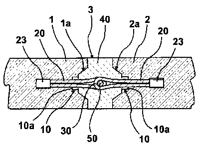
Dispositif servant à raccorder des sections de béton préfabriquées (1, 2), qui comprend un câble en forme de boucle (20) dont les sections (21, 22) formant la boucle (20) sont munies d'un dispositif (26, 29) qui les maintient penchées, le dispositif (26) étant une âme (29) qui se trouve à l'intérieur de la boucle (20) et peut se déformer.


Abrégé anglais


Device for joining pre-cast concrete parts (1, 2), comprising a cable loop
(20), wherein the cable sections (21, 22) forming the cable loop (20) have
means (26, 29) for keeping the cable sections in a bent-over position, the
means (26) is a cable core (29) which lies within the cable of the cable loop
(20) and which is plastically deformable.

Revendications

Note : Les revendications sont présentées dans la langue officielle dans laquelle elles ont été soumises.


7
CLAIMS.

1. A device for joining pre-cast concrete sections, the device comprising.

a cable loop having cable sections which form bent portions of the cable loop;
and

a plastically deformable element lying within each of the cable sections of
the cable loop;
wherein the cable sections are to be maintained in a bent-over position at
least for a
period after pre-casting in a precast concrete section and during
transportation and
storage of the concrete section

2. The device as claimed in claim 1, wherein the cable loop comprises a steel
cable, and
the plastically deformable element comprises a bendable wire

3. The device as claimed in claim 1, further comprising an insert body
insertable into a
recess of the pre-cast concrete section, wherein the insert body has at least
one opening
for the cable loop.

4. The device as claimed in claim 3, wherein the insert body has a U-shaped
profile and a
portion of the cable loop which will extend from the pre-cast concrete section
lies in a
channel of the U-shaped profile in the bent-over position

5. A pre-cast concrete section comprising a device as claimed in claim 1,
wherein the cable
loop has a loop-shaped end, which for joining to another pre-cast concrete
section
projects towards an opposite edge face of the other pre-cast concrete section,
and a
pressed end embedded in an edge portion of the pre-cast concrete section.

6. The pre-cast concrete section as claimed in claim 5, wherein an insert body
is inserted
into the recess of the pre-cast concrete section such that an open front edge
of the U-
shaped profile flush with a surface of an edge face of the pre-cast concrete
section.

7. The pre-cast concrete section as claimed in claim 5, wherein the concrete
section is a
wall element.


8
8. A device for joining pre-cast concrete sections, the device comprising:

a cable loop having cable sections which form bent portions of the cable loop;
and

a plastically deformable cable core lying within each of the cable sections of
the cable
loop;

wherein the cable sections are to be maintained in a bent-over position at
least for a
period after pre-casting in a precast concrete section and during
transportation and
storage of the concrete section.

Description

Note : Les descriptions sont présentées dans la langue officielle dans laquelle elles ont été soumises.


CA 02695604 2010-03-09
1

Device for connecting prefabricated concrete sections
DESCRIPTION

The present invention relates to a device for joining pre-cast concrete parts,
comprising a cable loop, wherein the cable sections forming the loop
comprise means for keeping the cable sections in a bent-over position. The
subject of the invention is also a pre-cast concrete part with a device of the
aforesaid kind.
A non-elastically deformable belt with an internally disposed core of stiff,
deformable material, which is surrounded by a plurality of twisted strands,
which in turn are surrounded by a casing, is known from FR-A-1602226.

Devices of that kind with a cable loop for joining pre-cast concrete parts,
particularly prefabricated wall elements of concrete, are well-known from
the state of the art. Devices of that kind usually comprise a retaining part
in
the form of a rail, which is of U-shaped construction and which at the end is
let into the pre-cast concrete part. It is necessary for transport and also
during mounting of such a pre-cast concrete part that the cable loop
substantially does not protrude beyond the end face. To that extent it has
to be achieved that the cable loop is received by the retaining part, i.e.
substantially does not protrude beyond the retaining part.

In this connection, various devices are known from the state of the art
which in principle do justice to this premise. Thus, for example, a receiving
box is known from EP 1 637 670 Al which has a removable cover, wherein
the cable loop, which projects through an opening on the rear side of the
receiving box, is held under stress by a spreading spring against the
removable cover during transport and also during mounting. When the
cover is removed, the cable loop shoots forward not only due to the bias


CA 02695604 2010-03-09

2
through the spreading spring, but also due to the resilient characteristics of
the cable loop and goes over, for example in the case of an upright wall
element, into an approximately horizontal position. That means the cable
loop extends in the direction of the end face of the opposite pre-cast
concrete part.

The outlay, which is instigated in accordance with the state of the art, in
order to keep the cable loop during transport and mounting in a state bent
over by approximately 900 and thus parallel to the upper side of the pre-
lo cast concrete part, is high and for that reason such devices are also very
expensive.

Moreover, a device is known from EP 0 914 531 B1, which similarly
comprises a U-shaped retaining part which has on the rear side a passage
opening for the cable loop, wherein the retaining part is of approximately U-
shaped construction and wherein the limbs are bent over inwardly at the
end. The cable loop now projects by its loop-shaped end through the
opening, which is arranged on the rear side, in the retaining part and bears
from within against the bent-over portions of the limbs of the retaining part.
After mounting, the cable loop is pulled by the loop-shaped end out of the
retaining part, wherein the cable loop snaps up.

Utility model DE 20 2007 011 243 U1 shows a similar construction insofar
as there a shaped part is provided for fixing the cable loop, which shaped
part has a mechanically positive couple with the section, which forms the
bent-over cable eye, of the cable on at least three sides and which shaped
part after casting of the concrete pre-cast concrete part is withdrawable
from the concrete pre-cast component and the cable eye.

In this connection the outlay for keeping the cable loop in the bent-over
state is relatively high, particularly because a specially constructed rail
has


CA 02695604 2010-03-09
3

to be produced as retaining part, wherein in addition the cable loop in the
transfer to the pre-cast concrete part is kept by an insert body in the
opening of the retaining part. This device is thus also comparatively
expensive.
Finally, a device is known from EP 0 534 475 BI in which an insert dish
part is provided as well as a cover, wherein the insert dish part receives the
cover by means of a snap connection. The loop-shaped end is kept parallel
to the end face of the pre-cast concrete part by the insert dish part in
conjunction with the cover. It is also the case here that production of such
a device is complicated and costly.

A cable transport anchor having a loop at the end is known from DE 33 22
646 Al. The guiding together and bending over of central cable regions are
carried out by a guiding and bending-over device which is formed by a
sleeve.

The object of the invention thus consists of producing a device of the kind
stated in the introduction which is particularly economic in manufacture, but
nevertheless reliably fulfils the same purpose as the state of the art. In
this
connection reference is made to the following:

The cable loop projects, as already mentioned, by its loop-shaped end after
mounting towards the end face of the opposite pre-cast concrete part. The
cable loop is disposed by its other end in the pre-cast concrete part. Once
the cable loop is released, i.e. has been freed from its bent-over position,
it
is not necessary for the cable loop to be transferred back to this starting
position, but it merely has to be ensured that during transport and during
mounting the cable loop remains in the bent-over position.


CA 02695604 2010-03-09

4
Taking this into consideration the device according to the invention is
distinguished by the fact that the means is a cable core which lies within the
cable of the cable loop and which is plastically deformable. The cable core
is thus, for example, an appropriately constructed metal wire, the stability
of
which is selected so that it is capable of keeping the cable loop in bent-over
position. In order to bring the cable loop by its loop-shaped end into the
unfolded position, merely a return bending process is required. From that it
is clear that the cable sections forming the loop are kept in their bent-over
position by means which are in direct connection with the cable loop itself
or are part of the cable loop. This is in complete contrast to the state of
the
art, where in each instance a separate device is required in order to keep
the cable loop in the bent-over position merely for transport and mounting.
Since this separate device is omitted, such a cable loop can be produced
substantially more economically. In particular, to that extent the possibility
also now exists of directly letting, or concreting in place, the cable loop in
the end face of a pre-cast concrete part, since - as already mentioned -
separate devices for keeping the cable loop in a bent-over position during
transport and during mounting are no longer required.

According to a further feature of the invention provision is made for the
cable loop to have an insert body, wherein the insert body has at least one
opening for the cable loop and is insertable into a recess of the pre-cast
concrete part. The insert body is, in particular, constructed to be of U-
profile shape in cross-section, wherein the web connecting the two limbs of
the insert body of U-profile shape has the opening for the cable loop. The
cable loop projects by its closed end through this opening, wherein this end
is also cast in place in the pre-cast concrete part. The cable loop lies by
its
bent-over loop-shaped end in the rail of U-profile shape in cross-section.

3o The subject of the invention is equally a pre-cast concrete part,
particularly
a wall element of pre-cast concrete, which is distinguished by at least one


CA 02695604 2010-03-09

device of the aforesaid kind. In detail, it is provided in this connection
that
the insert body is inserted at the end in the pre-cast concrete part in such a
manner that by the front edge it is flush with the surface. It is clear
therefrom that through the insert body set back relative to the end face a
5 denticulation with the casting mortar occurs during filling of the casting
gap.
The connection is thereby in a position of accepting shearing forces. On
the other hand, one or more reinforcing rods is or are pushed through the
cable loops which overlap one another as a pair in such a manner that an
eye results, whereby forces also acting in longitudinal direction of the cable
loops can be accepted by the cable loops.

The invention is explained in more detail in the following by way of example
with reference to the drawings.

Figure 1 schematically shows two pre-cast concrete parts which,
spaced from one another, form a joint;

Figure 2 shows a side view according to Figure 1;

Figure 3 schematically shows a cable loop with a core of a metal wire;
Figure 4 shows a bent-over cable loop; and

Figure 5 shows an illustration according to the line V - V of Figure 4.
The two pre-cast concrete parts 1 and 2 according to Figure 1 are disposed
at a spacing from one another with formation of a joint 3. The pre-cast
concrete parts 1 and 2 each have a trapezium-shaped recess 1 a or 2a at
the end face, wherein provided in the base of the trapezium-shaped recess
1a is an insert body 10 which is recognisably constructed to be of U-profile
shape in cross-section. The insert body 10 is cast in place, with surface


CA 02695604 2010-03-09

6
flushness, in the end face of the respective wall element 1 or 2. The web 9
of the insert body of U-profile shape has a passage opening 10b for the
cable loop, which is designated overall by 20. The ends of the cable loop
20 are connected together by a pressed member 23, wherein this part of
the cable loop is cast in place in the concrete of the pre-cast concrete part,
just as is the insert body 10. The cable loop 20 overlaps the adjacent cable
loop, wherein the eye 30 thereby formed receives a reinforcing rod 50. The
joint 3 is then filled with casting mortar 40.

io A side illustration of two pre-cast concrete parts connected together is
evident from Figure 2.

The cable loop 20 in the bent-over state of the loop-shaped end is
illustrated from Figure 3. In this connection the cable loop, which basically
consists of a steel cable, has a core in the form of a wire 29, which is
configured in such a manner that it is capable of keeping the wire cable, in
the bent-over state, in this position.

The insert body 10 with a cable loop 20 in bent-over state is depicted in the
illustration according to Figure 4. The insert body 10, which is constructed
to be of U-profile shape, has an opening 10b on its rear side (Figure 5).


Dessin représentatif
Une figure unique qui représente un dessin illustrant l'invention.
États administratifs

Pour une meilleure compréhension de l'état de la demande ou brevet qui figure sur cette page, la rubrique Mise en garde , et les descriptions de Brevet , États administratifs , Taxes périodiques et Historique des paiements devraient être consultées.

États administratifs

Titre Date
Date de délivrance prévu 2012-11-27
(22) Dépôt 2010-03-09
Requête d'examen 2010-03-15
(41) Mise à la disponibilité du public 2010-09-12
(45) Délivré 2012-11-27
Réputé périmé 2021-03-09

Historique d'abandonnement

Il n'y a pas d'historique d'abandonnement

Historique des paiements

Type de taxes Anniversaire Échéance Montant payé Date payée
Le dépôt d'une demande de brevet 400,00 $ 2010-03-09
Requête d'examen 800,00 $ 2010-03-15
Enregistrement de documents 100,00 $ 2010-06-07
Enregistrement de documents 100,00 $ 2012-02-02
Taxe de maintien en état - Demande - nouvelle loi 2 2012-03-09 100,00 $ 2012-02-13
Taxe finale 300,00 $ 2012-09-10
Taxe de maintien en état - brevet - nouvelle loi 3 2013-03-11 100,00 $ 2013-02-12
Taxe de maintien en état - brevet - nouvelle loi 4 2014-03-10 100,00 $ 2014-02-21
Taxe de maintien en état - brevet - nouvelle loi 5 2015-03-09 200,00 $ 2015-02-18
Taxe de maintien en état - brevet - nouvelle loi 6 2016-03-09 200,00 $ 2016-02-10
Taxe de maintien en état - brevet - nouvelle loi 7 2017-03-09 200,00 $ 2017-02-09
Taxe de maintien en état - brevet - nouvelle loi 8 2018-03-09 200,00 $ 2018-02-09
Taxe de maintien en état - brevet - nouvelle loi 9 2019-03-11 200,00 $ 2019-02-22
Taxe de maintien en état - brevet - nouvelle loi 10 2020-03-09 250,00 $ 2020-02-20
Titulaires au dossier

Les titulaires actuels et antérieures au dossier sont affichés en ordre alphabétique.

Titulaires actuels au dossier
PEIKKO GROUP OY
Titulaires antérieures au dossier
GENTIL, HUGO
KRUMMEL, GERHARD
Les propriétaires antérieurs qui ne figurent pas dans la liste des « Propriétaires au dossier » apparaîtront dans d'autres documents au dossier.
Documents

Pour visionner les fichiers sélectionnés, entrer le code reCAPTCHA :


Pour visualiser une image, cliquer sur un lien dans la colonne description du document. Pour télécharger l'image (les images), cliquer l'une ou plusieurs cases à cocher dans la première colonne et ensuite cliquer sur le bouton "Télécharger sélection en format PDF (archive Zip)" ou le bouton "Télécharger sélection (en un fichier PDF fusionné)".

Liste des documents de brevet publiés et non publiés sur la BDBC .

Si vous avez des difficultés à accéder au contenu, veuillez communiquer avec le Centre de services à la clientèle au 1-866-997-1936, ou envoyer un courriel au Centre de service à la clientèle de l'OPIC.


Description du
Document 
Date
(yyyy-mm-dd) 
Nombre de pages   Taille de l'image (Ko) 
Page couverture 2010-09-07 1 45
Changement de nomination d'agent / Changement No. dossier agent 2021-04-06 4 107
Lettre du bureau 2021-05-01 1 195
Lettre du bureau 2021-05-01 1 188
Abrégé 2010-03-09 1 9
Description 2010-03-09 6 222
Dessins 2010-03-09 2 40
Revendications 2010-03-09 1 27
Dessins représentatifs 2010-08-17 1 18
Abrégé 2011-11-29 1 9
Revendications 2011-11-29 2 48
Page couverture 2012-11-01 1 45
Correspondance 2010-08-31 1 25
Poursuite-Amendment 2010-03-15 1 31
Paiement de taxe périodique 2018-02-09 1 33
Cession 2010-03-09 4 106
Correspondance 2010-04-07 1 46
Poursuite-Amendment 2010-04-20 2 31
Correspondance 2010-04-29 1 75
Cession 2010-06-07 4 116
Correspondance 2010-06-07 4 88
Poursuite-Amendment 2011-09-09 2 69
Poursuite-Amendment 2010-06-23 1 29
Correspondance 2010-08-30 1 27
Correspondance 2010-11-22 3 55
Correspondance 2011-05-27 1 21
Correspondance 2011-11-10 1 46
Poursuite-Amendment 2011-11-29 8 227
Taxes 2012-02-13 1 163
Cession 2012-02-02 3 102
Correspondance 2012-02-23 1 20
Correspondance 2012-03-30 1 89
Correspondance 2012-09-10 1 34
Taxes 2014-02-21 1 33
Taxes 2015-02-18 1 33
Taxes 2016-02-10 1 33
Taxes 2017-02-09 1 33