Note : Les descriptions sont présentées dans la langue officielle dans laquelle elles ont été soumises.
CA 02695667 2010-02-04
WO 2009/073052
PCT/US2008/009682
METHOD AND SYSTEM FOR INFLIGHT
REFUELING OF UNMANNED AERIAL VEHICLES
BACKGROUND OF THE INVENTION
Pield of the Invention:
The present invention relates to aeronautics. More specifically, the present
invention relates to systems and methods for refueling vehicles in flight.
Description of the Related Art:
The use of unmanned air vehicles (UAVs) for various military and civilian
applications is rapidly expanding. A typical UAV flight has three parts to its
mission:
1) it must be launched frem a support base and fly to an area of operation; 2)
it must
loiter in its area Of operation while petfonning its intended functions; and
3) it must
fly back to its support base and land while carrying aufficient spare fuel to
account for
unforseen delays such as unfavorable headwinds.
At takeoff, a UAV must carry sufficient fuel for all three phases of its
mission.
It is often the case that mission Parts 1 and 3 will each consume as much fuel
as
mission part _2i which is the useful portion of its total flight.
If a UAV can be refueled in-flight in its area of operation, a substantial
increase in utility may be achieved. Hence, there is a growing need for a
system or
method for refueling UAVs in flight to allow the UAV to remain on-station for
extended periods without consuming time and fuel to return to its support
base.
1
CA 02695667 2010-02-04
WO 2009/073052
PCT/US2008/009682
Unfortunately, currently, it is generally not feasible for UAVs to be refueled
from conventional manned tanker aircraft. There are two primary reasons.
First, most
UAVs are much smaller and fly slower than conventional maimed tankers, which
have been designed to refuel large jet-powered aircraft. It is necessary that
the tanker
have a flight performance roughly comparable to the UAV in order to perform
close
formation flight during refueling operations. Specially constructed tanker
aircraft will
generally be required to refuel most UAVs.
Second, aircrews of manned tanker aircraft are unwilling to permit unmanned
aircraft to fly in close formation for safety reasons. During manned refueling
operations, skilled pilots are in control of both the tanker and receiving
aircraft. There
is considerable danger to the human crews in both aircraft should any
collision occur
during the extremely close formation flight. Pilots of both aircraft place a
very high
degree of trust in the skill and competence of the other pilot. They are
unwilling to
rely on the response of robotic unmanned vehicles that may not be able to
react to
unforeseen problems. An unmanned tanker aircraft will generally be required
for in-
flight refueling of UAVs.
Hence, a need remains in the art for a safe and cost-effective system or
method
for refueling a UAV in flight.
SUMMARY OF THE INVENTION
The need in the art is addressed by the system and method for refueling
= uinnamied aerial vehicles of the present invention. In the system
implementation the
invention is adapted to refuel a first unmanned aerial vehicle from a second
unmanned
aerial vehicle and includes an arrangement for flying the first and second
vehicles to
proximity within a predetermined range and for connecting an umbilical from
the
second vehicle to the first vehicle in flight using a novel magnetic targeting
system.
2
CA 02695667 2010-02-04
WO 2009/073052
PCT/US2008/009682
In the illustrative etiaboditnent, the targeting system includes a first Cbil
around
a refueling receptacle on the fist vehicle. A seeker is disposed at a first
end Of said
umbilical on the second 'vehicle. The seeker includes multiple detector coils
adapted
to detect a magnetic signal from the first coil around the receptacle on the
first
vehicle. The coils are Mounted Stich that the detector coils point in
different
directions. The outputs of the coils are processed to determine the direction
and range
to the Mission UAV from the tanker UAV.
In the illustrative embodiment, the inventive method includes the steps of
flying the first and second vehicles to proximity within a predetermined range
and
connecting an umbilical from the second vehicle to the first vehicle in flight
using the
magnetic targeting system. More generally, a targeting method is disclosed
including
steps Of providing a plurality of coils for detecting a magnetic field;
pointing each of
Said coils for optimal sensitivity of said field in a different direction; and
processing
signals output by said coils to locate a target. In the illustrative
embodiment, the
targeting system includes a coil disposed around a target on a first platform;
an
arrangement for activating the coil; and an arrangement disposed on a second
platforni
for sensing a field radiated by the coil.
A novel detector arrangement is also disclosed. The novel detector includes a
plurality of coils for detecting a magnetic field; an arrangement for pointing
each of
the coils for optimal sensitivity of the field in a. different direction; and
an
arrangement for processing signals output by the coils to determine a location
Of an
object.
3
CA 02695667 2014-06-02
In accordance with an aspect of the present invention, there is provided a
system
for refueling a first unmanned aerial vehicle from a second unmanned aerial
vehicle, the
system comprising: guidance means for flying the first and second unmanned
aerial
vehicles to proximity within a predetermined range; and means for connecting
an
umbilical from one unmanned aerial vehicle to the other unmanned aerial
vehicle in flight,
said means for connecting including a targeting system for magnetically
detecting a
refueling receptacle coupled to said first unmanned aerial vehicle, said
targeting system
including: a first coil disposed around said refueling receptacle on said
first unmanned aerial
vehicle, a second coil disposed around said refueling receptacle on said first
unmanned aerial
vehicle, means for exciting said first coil with a first signal at a first
frequency and exciting
said second coil with a second signal at a second frequency which is different
from said
first frequency, a seeker disposed at a first end of the umbilical on said
second unmanned
aerial vehicle, said seeker including first and second detector coils adapted
to detect at
least one of the magnetic signals from said first and second coils, and logic
means for
receiving the at least one of the magnetic signals by at least one of said
first and second
detector coils and determining a direction and a range to said refueling
receptacle from
said umbilical in response thereto.
In accordance with a further aspect of the present invention, there is
provided a
method for refueling a first unmanned aerial vehicle from a second unmanned
aerial
vehicle, the method comprising: flying the first and second unmanned aerial
vehicles to
proximity within a predetermined range; and connecting an umbilical from the
second
unmanned aerial vehicle to the first unmanned aerial vehicle in flight using a
targeting
system, wherein connecting comprises: detecting a magnetic field with a
plurality of
detector coils; pointing each of the plurality of detector coils for optimal
sensitivity of the
magnetic field in a different direction; and processing signals output by the
plurality of
detector coils to locate a target.
3a
CA 02695667 2010-02-04
WO 2009/073052
PCT/US2008/009682
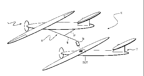
BRIEF DESCRIPTION OF THE DRAWINGg
figure 1 is a simplified aerial view showing two unmanned aerial vehicles in
flight flying in close proximity to effect autonomous refueling in accordance
with an
illustrative embodiment of the present teachings,
Figure 2 is a diagram that illustrates the generation of a magnetic field by
an
energized coil.
Figure 3 is a top view of a section of the mission UAV of Figure 1 in a first
embodiment of the coil thereof in accordance with the present teachings.
Figure 4 is a side view the mission UAV of Figure 1 in a second embodiment
in accordance with the present teachings by which the receptor coil is
disposed in a
basket coupled to the UAV via a flexible fuel line. =
Figure 5 is an end view of an illustrative embodiment of the basket of Figure
4.
Figure 6 is a simplified diagram of the fuel probe seeker of the system of
Figure 1 in accordance with the present teachings.
Figure 7 is a sectional side view of a portion of the seeker of Figure 1 in
accordance with an illustrative embodiment of the present teachings.
Figure 8 is a simplified block diagram of the electrical subsystem of the
mission UAV in accordance with an illustrative embodiment of the present
teachings.
Figure 9 is a simplified diagram of the seeker electronics of an illustrative
implementation of the UAV tanker seeker/targeting system of the present
invention.
Figure 10 is a block diagram of an illustrative implementation of a UAV
tanker seeker precision guidance computer in accordance with an illustrative
embodiment of the present teachings.
4
CA 02695667 2010-02-04
WO 2009/073052
PCT/US2008/009682
Figure 11 is a flow diagram of an illustrative embodiment of a method for
refueling an unmanned aerial vehicle in accordance with the present teachings.
DESCRIPTION OF THE INVENTION
Illustrative embodiments and exemplary applications will now be described
with reference to the accompanying drawings to disclose the advantageous
teachings
of the present invention.
While the present invention is described herein with reference to illustrative
embodiments for particular applications, it should be understood that the
invention is
not limited thereto. Those having ordinary skill in the art and access to the
teachings
provided herein will recognize additional modifications, applications, and
embodiments within the scope thereof and additional fields in which the
present
invention would be of significant utility.
Figure 1 is a simplified aerial view showing two unmanned aerial vehicles in
flight flying in close proximity to effect autonomous refueling in accordance
with an
illustrative embodiment of the present teachings. As shown in Figure 1, the
system 10
includes a mission UAV 12, a tanker UAV 14 and a novel magnetic targeting
arrangement 16 for guiding an umbilical 18 to effect a refueling coupling
between the
two vehicles. Each UAV has an airframe, control surfaces and guidance,
navigation,
communication and propulsion systems as is common in the art.
As per conventional teachings, the mission UAV 12 has the following
systems:
1. Mission Package: Mission Data Link, sensors, other payloads (i.e. a
broadcast transmitter, guided missiles, etc).
2. Flight Systems: engine and fuel management, flight instrtunents, flight
control
servos, autopilot computer.
5
CA 02695667 2010-02-04
WO 2009/073052
PCT/US2008/009682
3. Navigation Systems: GPS receiver, inertial navigator, air traffic radar
transponder, collision avoidance systems.
4. Flight Management Computer:
- Contains pre-programmed course, waypoints, altitude, and speed
information.
- Directs the autopilot, engine, takeoff and landing sequence, collision
avoidance maneuvers, etc.
= - Monitors fuel consumption, electric power, and other vehicle health
information.
- Communicates with the Ground Control Operator and receives mission
change instructions.
- Executes fail-safe maneuvers if control links are lost.
5. Control Data Links:
- May include two or more redundant radio links from the UAV to the
Ground Control pilot-operator.
- Includes transmitters, receivers, antennas, possibly a satellite tracking
antenna.
- Also provides for transmission security such as encryption, passwords,
bit
error checking.
- Provides a two-way voice channel to the Ground Controller for air-to-air
communication.
6. Air Traffic Radios:
- Typically the Ground Controller is able to communicate from the UAV to
other aircraft and Air Traffic Control.
- Conventional aircraft radios are installed on the UAV. They are operated
_
through the Control Data Link. =
For mid-air refueling in accordance with the present teachings, the mission
UAV 12 will have the following additional systems:
6
CA 02695667 2010-02-04
WO 2009/073052
PCT/US2008/009682
1. a refueling port:
- a fixed port on the UAV structure or alternately a flexible hose and basket
which are deployed during refueling;
2. software in the flight management computer to communicate position
information to the tanker UAV; and
3. a precision guidance system to allow an unmanned tanker to connect to the
fuel port.
In accordance with the present teachings, the tanker UAV 14 operates as
another UAV in the air space and has systems similar to the mission UAV 12
including:
1. a ground control station and human pilot-operator;
2. the mission package will include a large fuel tank, pumps, metering
sensors, and a deployable fuel probe; and
3. flight systems, navigation systems, flight management computer, control
data links, air traffic radios.
In addition, as discussed more fully below, the tanker is designed to locate
the
mission UAV, intercept its course, join up in close formation, and maneuver
its fuel
probe to connect with the fuel port on the mission UAV.
In addition, the tanker includes:
- a system for precision maneuvering of a fuel probe either by maneuvering
the entire aircraft and/or separately steering the probe;
- a precision guidance system to direct the fuel probe-to the mission UAV fuel
port; and
- probe sensors to detect mechanical strains after a mechanical latch has
been
achieved.
7
CA 02695667 2010-02-04
WO 2009/073052
PCT/US2008/009682
In accordance With the invention, when the mistion UAV 12 is in heed of fuel,
it will enter a standardized holding pattern that has been approved by an air
traffic
controller. As i5 common in the art, the holding pattern may be a racetrack
path flown
at constant altitude in a block of airspace that has been cleared of other
aircraft
operations. The unmanned tanker aircraft 14 will he directed to the holding
area by its
ground =contest station. The receiving Mission UAV 12 May COntirmOutly
transmit its
position and altitude information by radio. The position information may be
derived
from an onboard satellite navigation receiver such as a Global Positioning
Satellite
(GP S) receiver.
The mission computer on board the tanker UAV 14 compares the received
infomiation to its own position and calculates a safe intercept Course. For
example,
the tanker 14 may approach the receiver from above and slightly ahead as shown
in
=
Figure 1. Many other approach configurations are possible.
Once the tanker and receiver are in loose formation flight, the tanker will
transition to close formation flying. In general, the tanker aircraft will be
equipped
with special systems to permit both loose and close formation flight. By
placing most
specialized systems in the tanker 14, the receiving UAV 12 will require
minimal
modification to permit it to participate in in-flight refueling. Since a
tanker aircraft
may service multiple receiving aircraft, it is cost effective to place
specialized systems
mostly in the tanker.
Loose formation flying may be defined as coordinated flight between two
aircraft which can be accomplished by reference to external radio navigation
aides
such as the GPS system. Close formation flight may be defined as the extreme
positional= accuracy required for the tanker UAV to connect its refueling
probe to a
receptacle on the receiving UAV. In general, the tanker must maneuVer its
refireling
probe to close proximity (e.g. within approximately 2 centimeters of the
receiving
receptacle) in order to achieve a mechanical latch. The tanker must then
maintain
close formation flight during the transfer of fuel. This extreme precision
must be
8
CA 02695667 2010-02-04
WO 2009/073052
PCT/US2008/009682
accomplished while both aircraft are subject to unpredicted changes in Winds
and
turbulent air currents.
Close formation flying may be achieved by providing a cooperative target on
the receiving UAV and a matched seeker mechanism on the tanker UAV. Many
embodiments of cooperative targets are possible. For example, the receiving
target
May emit radio signals, OpticEil Signals, Magnetic fields, electric fields,
radioactiVe
emissions, or acoustic signals. From these emissions, the seeker on the tanker
is able
to derive clirection.and range information to the cooperative target. This
information is
used by a computer on the tanker for two funCtions, It provides guidance
information =
to flight controls on the tanker aircraft to maintain close flight. It also
provides
guidance information used to independently maneuver the refueling probe as it.
approaches the receiving receptacle
= As a practical matter, many of the above listed emissions are unsuitable
or
have serious limitations for seekers for unmanned aerial refueling probes. For
example, it would seem reasonable for the target aircraft to radiate a radio
wave that
the tanker could use as a homing signal. In practice, radio waves are not a
good choice
for very close homing distances, Wheln radio (or microwave) waves are
radiated, they
are subject to strong multipath reflections from various parts of the nearby
aircraft
= body. Furthermore, as the seeker antenna approaches a radio wave source,
it merges
the near field patterns and side lobes of both the transmitting and receiving
anten a-s.
The result is confused and rapidly changing apparent directions to the target.
Another reasonable seeker approach might be to use optical sources and
detectors. The target could be provided with flashing lights and the seeker
can use
= well-known optical imaging methods to provide guidance signals. As a
practical
= 25 matter, the optical seeker suffers from several deficiencies. Most
simple optical
= systems have a limited field of view. The complexity of the optical
system rises
rapidly when it is required to search a very large field of view to find the
active target.
Most importantly, optical systems are very easily disrupted by fog, rain,
water drops
on the optical surfaces, mud and oil that may be common in aircraft
operations.
9
CA 02695667 2010-02-04
WO 2009/073052
PCT/US2008/009682
In accordance with the present teachings, a coil 20 is provided around a
receptacle 22 a the Mission UAV 12. The coil 20 is powered with an electrical
current and emits a magnetic field in response thereto. This is illustrated in
figure 2.
The magnetic field is sensed by a seeker 30 disposed at the end of the
umbilical (fuel
probe) 18 of the tanker UAV 14. In the preferred embodiment, the seeker =30
inCludes
thiatiPle detectOr coils (not shown in Figure 1) that sense the Magnetic field
emanated
by the receptor coil 20.
The signals are processed to= provide range and direction precisien guidance
commands to a mechanism to maneuver the umbilical as discussed more fully
below.
In Figure 1, themechanism is a boom 32.
- Figure 2 is a diagram that illustrates the generation of a magnetic
*field hy an
energized coil. Figure 2 shows a cooperative target and seeker based on the
principle
of magnetic induction. When a current flows through a wire loop or coil, a
dipole
magnetic field pattern develops in the near space surrounding the coil. If the
current
flowing through the coil is alternating current, then an alternating dipole
magnetic
field i generated in the vicinity of the coil. The alternating magnetic field
readily
induces voltages and currents in any nearby unpowered coils, which may be used
in a
seeker. It is important to note that the dipole magnetic field is not a
radiated radio
wave. With dipole sources, the magnetic field strength drops very rapidly with
distance from the sourpe coil. In general, the magnetic field strength
decreases with
distance R from the energized coil by a factor of (I/R)3. That is, magnetic
induction
signals drop off in signal strength approximately as 1/(range3). This is a
very rapid
drop.
Since the signal strength drops so rapidly with distance, the range to the
target
may be estimated quite accurately by simply measuring the strength of the
detected
signal. If the source strength of the target is held constant, measuring the
received
strength gives a very good estimate of the range to the target. Unlike radar
systems, it
is not necessary to send two-way signals to measure range. With the coil
dimensions
and drive current shown in Figure 2, the target can be located a distance of
(e.g. 15
CA 02695667 2010-02-04
WO 2009/073052
PCT/US2008/009682
meters) from the seeker. In accordance with the present teachings, a seeker
uses plural
detector coils to determine direCtion to the target in twO dimensions. Each
coil pOints
in a different direction. The coil which is Most clotely aligned with the
source
produces the strongest 'signal. When the signal is equally ballanced in all
coil's, the
target lies directly ahead. The seeker logic (discussed below) provides output
signals
to adjust the flight controls and to Maneuver the refueling prObe.
Hence, the coil 20 is activated by an alternating current from a generator 24.
hi an illustrative embodiment, the Coil 20 has 10 turns, of a suitable
conductor such as
18 gauge copper wire, wrapped on a dielectric or air core of diameter of
approximately 60 centimeters and the generator 24 outputs an alternating
current of
approximately- 100 milli-amperes at 5 kilohertz (kHz). Those skilled in the
art will
appreciate that the present invention is not limited to the coil design or the
level or
frequency of the power applied thereto.
Figure 3 is atop view of a section of the mission UAV 12 of Figure 1 in a
first
embodiment of the coil thereof in accordance with the present teachings. In
this
embodiment, the Coil 20 is disposed around a refueling port or receptacle 22
in an
aperture provided in a top surface 26 of the airframe of the mission UAV 12.
As
shown in Figure 3, in the best mode, an optional second coil 28 is included
for more
precise targeting as discussed more fully below.
Figure 4 is a side view the mission UAV 12' of Figure 1 in a second
embodiment in accordance with the present teachings by which the receptor coil
20' i
disposed in a basket 32' coupled to the UAV via a flexible (e.g. rubber) fuel
line 34'.
Figure 5 is an end view of an illustrative embedimerit of the basket 32' of
Figure 4. As shown in Figure 5, the basket 32' includes a cone 36' fabricated
of
metal, plastic, or fabric with a fuel .-port 22' disposed at a tep-center
portion thereof in
conununication with a fuel reservoir (not shown) on the UAV 12. The first coil
20' is
disposed at a distal end of the basket 32' relative to the fuel port 22'. A
second coil
28' is disposed between the first coil 20' and the fuel port 22'. Those
skilled in the art
will appreciate that the inyention is not limited to the fabrication of the
basket. That
11
=
CA 02695667 2010-02-04
WO 2009/073052
PCT/US2008/009682
is, the basket 32' may be of a solid, mesh or web construction and/or shaped
to fly in a
desired mariner without departing from the scope of the present teachings.
Figure 6 is a simplified diagram of the fuel probe seeker of the system of
Figure 1 in accordance with the present teachings. In the best mode, the
seeker 30
includes four detector coils 40 ¨ 43 (of which only two are shown in Figure
6). In the
illustrative embodiment, each detector coil is implemented with 400 turns of a
suitable conductor such as 22 gauge copper wire around an iron core
approximately 2
centimeters in diameter. The detector coils are mounted to point in separate
directions. The detector coils sense the magnetic field radiating from the
receptor
coils. The output of each detector coil is amplified by an associated
amplifier 44 ¨ 47
and input to a processor 50. The coil which points mOst directly toward the
receptor
coil 20 of the mission UAV will have the largest signal amplitude. The
processor 50
compares the outputs of the detector coils and calculates the range and
direction to the
receptor coil 20 as discussed more fully below. The range and direction
processor 50
may be implemented in discrete logic circuits, field-programmable gate arrays,
application-specific integrated circuits, or other suitable means. In the best
mode, the
processor 50 is implemented in software adapted to run on a general-purpose
computer (not shown) as discussed more fully below.
Figure 7 is a sectional side view of a portion of the seeker of Figure 1 in
accordance with an illustrative embodiment of the present teachings. As shown
in
Figure 7, the seeker 30 includes four magnetic detector coils 40 ¨ 43 (of
which only
two 40, 42 are shown in Figure 7). The coils 40, 42 are disposed within a
nonmetallic
housing 48 at a distal end of the fuel line 18. The amplifiers 44 ¨ 47 are
also disposed
within the housing 48. Wiring from the amplifiers is enclosed within a sheath
52
around the fuel line 18 and as discussed more fully below, outputs signals at
5 and 7
_ _
kHz in an illustrative embodiment thereof.
As is common in the art, the fuel line 18 has a ball and spring check valve
arrangement 60 at the distal end thereof. The spring loaded ball check valve
60 is
12
CA 02695667 2010-02-04
WO 2009/073052
PCT/US2008/009682
deSigned to open the line 18 and permit fuel to flow therethignigh after a
sticcesafully
latching operation.
Figure 8 is a simplified bloclg diagram of the electrical subsystem of the
mission UAV in accordance with an illustrative embodiment of the present
teachings.
As shown in Figure 8, in= the preferred embodiment, the mission UAV electrical
subsystem 10 includes first and second signal sourcea 74 and 76 which operate
under
control of a conventional onboard flight management computer 72. The first
source
74 drives the first coil 20 and the second source drives the second (inner)
coil 76. In
the illustrative embodiment, thç first and second sources 74 and 76 are
oscillators
operating at 5 kHz and 7 kHz, respectively.
Figure 9 is a simplified diagram Of the seeker electronics of an illustrative
implementation of the UAV tanker seeker/targeting system of the present
invention.
As shown in Figure 9, the seeker electronic subsystem 80 includes a set of
bandpass
filtera (e.g. 82, 84) for each detector coil (of which only two 40, 42 are
shown in
Figure 9). Each bandpass filter (BPF) is coupled to an associated power
detector 90,
92, 94 or 96. It should be noted that this embodiment has four detector cciils
and four
amplifiers are included along with eight bandpass =filters and eight power
detectors.
Nonetheless, the invention is not limited to the number of detectors or the
arrangement by which the detector outputs are processed. Each power detector
outputs a voltage proportional to the power level of the signal detected by
the
= associated coil.
In Figure 9, the first and third detectors illustrated 40 and 42 are coaxial
for the
purpose of discussion. It should be understood that the second and fourth
detectors 41
and 43 (not shown) are also coaxial With respect to an axis that is orthogonal
with
respect to that of the first and third detectors and coupled an identical
circuit 80.
Hence, the following discussion with respect to signal. processing will be
understood
to apply to both sets of detectors. The magnetic signal from each receptor
coil 20, 28
as detected by each detector coil 40 is summed with the signal from the other
detector
coil 42 for a given axis to determine range by first and second summing
arnplifiers 91
13
CA 02695667 2010-02-04
WO 2009/073052
PCT/US2008/009682
and 97. Likewise, the magnetic signal from each receptor coil 20, 28 as
detected by
each detector coil 40 is subtracted from the signal from the other detector
coil =42 for a
given axis to determine direction by first and second summing amplifiers 91
and 97.
The range and direction values from the sum and difference amplifiers for each
axis,
provided by each pair of detector coils 40/42 and 41/43, are fed into a
precision
guidance computer 100 illustrated in Figure 10.
Figure 10 is a block diagram of an illustrative implementation of a UAV
tanker seeker precision guidance computer in accordance with an illustrative
embodiment of the present teachings. The computer 100 includes an analog-to-
digital
A/D converter 102, 104, 106, and 108 for each of the amplifiers 91, 93, 95 and
97,
respectively, of Figure 9. Next, a first processor 110 estimates range with
respect to
the magnetic signal detected from the outer coil 20 of Figure 8 and a second
processor
116 estimates range with respect to the magnetic signal detected from the
inner coil 28
of Figure 8. Likewise, third and fourth processors 112 and 114 ascertain angle
with
respect to the magnetic signal detected from the inner coil 28.
Next, the range and angle outputs with respect to the outer coil 20 are
processed (118) to ascertain speed and steering commands for the closing rate
of the
seeker 30 from the autopilot computer 132. Likewise, the range and angle
outputs
with respect to the inner coil 28 are processed (120) to ascertain speed and
steering
commands for the short-range closing rate of the seeker 30 from the autopilot
computer 132.
When a predetermined short range to target is detected, a signal (122) is
output
which activates a switch 124, which, in turn, selects the short-range speed
and
maneuvering commands (122) for input to the aUtopilot computer 126. Autopilot
= operation is enabled by a signal (128) from a conventional onboard flight
management
computer 130 on detection of sufficient proximity to activate the autopilot
126. The
flight management computer 130 is coupled to an onboard communication system
132. The autopilot 126 provides short-range guidance commands for the
maneuvering
fins 54 and 56 of the seeker 30 (Figure 7) to effect a successful docking of
the seeker
14
CA 02695667 2010-02-04
WO 2009/073052
PCT/US2008/009682
probe 30 from the tanker UAV 14 with the refueling port receptacle 22 of the
mission
UAV 12 (Figure 1).
Figure 11 is a flow diagram of an illustrative embodiment of a method for
refueling an unmanned aerial vehicle in accordance With the present teachings.
At
steps 202 and 204, a refueling comtnand is issued to the mission UAV 12 and
the
tanker UAV 14 by timed pre-program or cotrunand from ground control. At step
206,
the mission UAV flies to and joins a continuous racetrack course around
designated
GPS waypoints. At step 208, the tanker UAV flies to and joins the continuous
racetrack course around the designated GPS waypoints at a safely higher
altitude. At
step 210, the mission UAV transmits an identification code and local GPS
position
coordinates by air-to-air radio at predetermined (e.g. 30 second) intervals
and listens
for a tanker reply. At step 212, the tanker UAV listens for mission UAV
position
reports. On receipt of a position report, the tnnker UAV sends a reply. On
receipt of
the reply (step 216), the mission UAV increases the GPS position report
interval to 3
seconds, for example, and at step 224 activates the fuel port precision
guidance
magnetic beacon (coils 20 and 28). At step 218, the tanker detects the
increased
frequency of position reports and at step 220 uses the mission UAV position
reports
and the expected racetrack course to compute an intercept path to arrive at
safe (e.g.
10 meter) distance above and behind the target.
Then, at step 222, the tanker deploys the refueling probe 16 (Figure 1) and
activates precision guidance detectors 40 ¨ 43 (Figure 9). At step 226, the
tanker
checks for predetermined (e.g. 15 meter) proximity. If the proximity threshold
is
detected, then at step 230, the tanker switches from GPS guidance to precision
guidance using signals from the magnetic fuel probe seeker (30) and at step
232 closes
.25 in range until pechanical lock (successful docking) is achieved. The
mechanical lock -
is detected by the mission UAV (step 234) and the two UAVs hold close
formation
using fuel probe strain gauge signals. At step 236, the mission UAV stops
radio
transmission of GPS position reports and, at step 238, sends a signal to start
the flow
of fuel. On receipt of the 'start fuel' signal, the tanker transfer fuel pumps
are
CA 02695667 2014-06-02
activated until receipt of a 'stop' signal from the mission UAV or the missiOn
UAV
disconnects or when an expected load is reached or some other preprogrammed
stop
condition (step 242): When its tks are full, the taissithi UAV sends a Signal
to Stop
the floW:of fuel (step 240) and diSdonileas the tefUeling. probe (step. 244).
At -Steps
246, 248 and 250, on detection of a mechanical disconnect, the tanker
maneuvers
safely away from the mission-1)AV and resumes normal navigation. At step 252,
the
tanker-sends a 'tanker clear' signal to the mission UAV. At steps 254, 256 and
258
the -mission UAV waits for the 'tanker clear' message i deactivates the file1
port
precision guidance beacOn and resumessnonnalhaVigation.
hi the method of Figtht 11, each step is repotted by a data link to a UAV
ground COntrol station. *The calculatiOns are performed by each UAV's
'associated
flight management computer.
Thus, the present invention has been described herein Vvith reference to a
particulat embodiment for a particular application. Those having ordinary
skill in the
art and access tó the present teachings will recognize- additional
modification
appliCaticins and embodiments within the scope thereof.
Ii is therefore intended by the appended claims to covet any and all such
applications, modifications and embodiments within the scope of the present
invention:
Accordingly,
16