Note : Les descriptions sont présentées dans la langue officielle dans laquelle elles ont été soumises.
CA 02695837 2010-03-05
=
AUTOMATED HIGH VOLUME SLIDE STAINING SYSTEM
The present invention relates to medical diagnostic equipment. The invention
has
particular utility in connection with the automated staining of biological
samples on
microscope slides, and will be described in connection with such utility,
although other
utilities are contemplated.
Many tissues do not retain enough color after processing to make their
components visible under a bright-field microscope. Accordingly, it is a
common
practice to add color or dies to tissues by staining them. The hematoxylin and
eosin
("H&E") stain is probably the most widely used histological stain. Its
popularity is based
on its comparative simplicity and ability to demonstrate clearly an enormous
number of
different tissue structures. Hematoxylin can be prepared in numerous ways and
has a
widespread applicability to tissues from different sites. Essentially, the
hematoxylin
component stains the cell nuclei blue/black, with good intranuclear detail,
while the eosin
stains cell cytoplasm and most connective tissue fibers in varying shades and
intensities
of pink, orange and red.
Accurate diagnosis depends on a pathologist or cytologist examining stained
microscope slides, usually H&E paraffin sections, the H&E staining having been
carried
out in bulk by an automated staining machine. The need for consistency is
vital to avoid
difficult histological interpretation. In general, automated staining machines
allow
accurate and consistent staining, differentiation and dehydration by adjusting
the times of
each step.
Certain standard procedures usually apply to the staining of tissues on the
slides.
Paraffin sections first must be de-paraffinized, because most stains are
applied in either
aqueous or alcoholic solutions and will not penetrate paraffin-infiltrated
tissues. After
the slides are de-paraffinized, the slides typically are baked in an oven or
other heated
chamber to drive off de-paraffinizing solvent, and adhere the tissues to the
slides. The
1
CA 02695837 2010-03-05
tissues may then be stained using, for example, standard stains such as
hematoxylin and
eosin. Finally, coverslipping is performed by adhering a thin glass coverslip
to the
stained tissue section, and then sealing it with a mounting agent, thereby
creating a
hermetically sealed environment suitable for archiving. Heretofore, all of
these steps
have been manually performed by a histotechnologist, a vanishing breed of
laboratory
technician dedicated to the art of preparing and staining of human tissue
samples for
reading and interpretation by a Pathologist.
There exists a need to automate all of the steps from de-paraffinizing through
coverslipping in histotechnology.
The present invention provides an automated slide-staining system for
application
of stains to biological tissue sections mounted on microscope slides. More
particularly,
the present invention provides an automated apparatus for deparaffinizing,
staining and
coverslipping a plurality of biological specimen bearing slides, in a fully
automated and
integrated system. In a preferred embodiment, the present invention provides
an
automated apparatus comprising a plurality of stacked work stations wherein
specimen
carrying slides may be dried, baked, de-waxed and prepped for staining, stains
applied,
and the slides sealed or covered so that the slides may then be stored for
future analysis
and study or as a permanent record of the analysis performed, and a transport
elevator for
moving a slide tray bearing a plurality of specimen slides between the
plurality of work
stations. In yet a further embodiment, the invention is directed to a method
of
automatically preparing tissue samples on microscope slides for pathological
analysis,
comprising baking the tissue sample onto the slide by having the instrument
apply heat to
the tissue sufficient to adhere it to the slide; deparaffinizing the tissue
sample by
contacting it with deparaffinizing fluid at a temperature above the melting
point of the
paraffin, and subsequently rinsing the liquefied paraffin away; staining the
tissue sample
by contacting it with a staining reagent; and coverslipping the slide by
contacting the
stained tissue sample on the slide with a pre-glued coverslip and an adhesive
activating
fluid.
2
CA 02695837 2010-03-05
Further features and advantages of the present invention will be seen from the
following detailed description of the invention, taken in conjunction with the
following
drawings wherein:
FIG. I is a simplified plan view and FIGS. IA and 1B are fragmentary front and
rear perspective views of an automated high-speed staining apparatus made in
accordance
With a first embodiment of the present invention;
FIG. 1C is a perspective view from the inside, and FIG. ID a perspective
exploded view from the outside of the tray storage station or "garage" portion
of the
present invention;
FIG. 2 is a perspective view and FIG. 2A an exploded view showing details of a
specimen slide supporting tray employed in the present invention;
FIG. 3 is an exploded perspective view of a de-paraffinizing module portion of
a
first embodiment of the present invention;
FIG. 3A is a top plan view of the nozzle and manifold portion of the de-
paraffinizing module of FIG. 3;
FIG. 4 is a view, similar to FIG. 3, of the heating or baking module of a
first
embodiment of the present invention;
FIG. 5 is a perspective view showing details of the de-paraffinizing fluid
recovery
system of a first embodiment of the present invention;
FIG. 6 is a schematic plumbing diagram of the de-paraffinizing fluid system of
a .
first embodiment of the present invention;
FIG.7 is a view, similar to FIG. 3, of a stain applicator station module of
the
present invention;
FIG. 8 is a perspective view of the coverslipper module of the present
invention;
FIG. 8A is a perspective view of a coverslipper cartridge portion of the
coverslipper module shown in FIG. 8;
FIG. 9 is an exploded view showing details of the slide tray transport and
elevator
portion of the present invention;
3
CA 02695837 2010-03-05
FIGS. 10A and 10B are two different perspective views showing details of the X-
Y table of the slide tray transport and elevator portion of the present
invention;
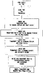
FIG. 11 is a flow diagram illustrating a first embodiment of the present
invention;
and
FIG. 12 is a view, similar to FIG. 1, of a second embodiment of an automated
high-speed staining apparatus made in accordance with the present invention;
FIG. 13 is an exploded view of a combination baking and de-paraffinizing
module
portion of the second embodiment of the present invention; and
FIG. 14 is a view, similar to FIG. 11, of a flow diagram illustrating the
second
embodiment of the present invention.
The staining system of the present invention performs all the steps of
processing,
staining and coverslipping of slide mounted biological samples in an efficient
high-speed
input operation. More particularly, slides bearing biological samples are
placed on a
slide tray, and the slide tray bearing the sample slides are loaded into the
system in
accordance with the present invention wherein the slides are conducted through
a
sequence of steps in which the slides are baked, de-waxed, stained and finally
coverslipped. A method of the present invention is directed to a method of
automatically
preparing tissue samples on microscope slides for pathological analysis,
comprising
baking the tissue sample onto the slide by having the instrument apply heat to
the tissue
sufficient to adhere it to the slide; deparaffinizing the tissue sample by
contacting it with
deparaffinizing fluid at a temperature above the melting point of the
paraffin, and
subsequently rinsing the liquefied paraffin away; staining the tissue sample
by contacting
it with a staining reagent; and coverslipping the slide by contacting the
stained tissue
sample on the slide with a pre-glued coverslip and an adhesive activating
fluid.
Referring to FIG. 1 of the drawings, the apparatus 20 of the first embodiment
of
the invention functions as one component or module of a system 22. System 22
also
includes bulk fluid containers 32, 34, 36 and related equipment.
Referring also to FIGS. lA and 1B, apparatus 20 includes a frame 40 supporting
a
stack of workstations comprising, for example, one or more drying or baking
stations or
4
CA 02695837 2010-03-05
=
modules 120, de-waxing or de-paraffinizing station or module 140, one or more
staining
stations or modules 160 and a coverslipping station or module 180 arranged in
a tower
50. A transport and elevator mechanism 52 is provided adjacent tower 50 for
transporting a slide tray 54 designed to carry a plurality of individual
specimen bearing
slides 56 from a tray storage station or "garage" 60 through drying,/baking,
de-waxing,
staining and coverslipping operations.
Referring in particular to FIGS. 1B and 1C, the tray storage garage or station
60
comprises a pair of stanchions 62A, 62B bearing a plurality of vertically
spaced shelves
or skids 64 for accommodating slide trays 54. Referring also to FIG. 1D, tray
storage
station or garage 60 includes a pivotally mounted door providing access to a
first shelf
position (for clarity, the outside skin or cover to garage 60 has been
omitted). A tray
drive assembly indicated generally at 68 including a pair of rotatably mounted
drive
wheels 70 driven by a drive motor and transmission 72 is positioned under the
first shelf
position for moving a tray into and out of the portal 66.
Referring in particular to FIGS. 2 and 2A, the slide tray 54 preferably
comprises a
pan or slide tray 80 having a generally rectangular plan, including a bottom
wall 82,
opposed side walls 84 and opposed end walls 86. The slide tray typically is
formed by
conventional injection molding using synthetic polymers intended for such use,
which are
well-known in the art.
Tray 80 includes a specimen slide supporting rack 90 for holding specimen
slides
in a substantially horizontal position in the same plane. Holding all the
slides in the same
plane facilitates baking and drying, as will be described below, and also
prevents cross-
contamination of slides during de-paraffinizing and staining as will be
described below.
= Rack 90 includes a plurality of slide spring supports 92 that limit the
axial, lateral and
vertical movement of specimen slides 56 once placed on the slide tray. Rack 90
is
supported above tray bottom 80 at sufficient height to discourage or prevent
the
formation of films or bubbles forming between the specimen slide bottom and
the tray
bottom. Slide spring supports 92 hold the individual specimen slides in
position by
exerting force on opposing edges 96 of the specimen slides. The floor of the
slide tray is
5
CA 02695837 2010-03-05
sloped towards the middle to facilitate drainage to a central location 104 for
evacuation of
de-waxing fluids and stains, as will be described in detail hereinafter. Tray
80 permits
the automated handling of a plurality of specimen slides through of the steps
of
drying/baking, de-paraffinizing, staining and coverslipping. In a preferred
embodiment,
tray 80 includes splash rails 106 and is arranged to accommodate 16 specimen
slides
arranged in a generally horizontal grid two slides wide and eight slides tall.
In the illustrated embodiment, the staining system comprises a drying/baking
station or module 120, a de-paraffinizing station or module 140, a staining
station or
module 160 and a coverslipping station or module 180 vertically arranged in
tower 50
and controlled by a computer.
Referring to FIG. 4, drying/baking station 120 comprises a thermally-insulated
compartment into which is supplied controlled heat for drying specimen slides.
Drying/baking station 120 preferably comprises a modular unit and includes a
convection
heater 122, arranged to direct a flow of heated air across the surfaces of the
specimen
slides. One feature and advantage of the present invention which results from
the
horizontal presentation of the slides is that convection drying is
particularly efficient.
Referring in particular to FIGS. 3 and 3A, de-paraffinizina station 140
comprises
a modular compartment and includes one or a plurality of wash dispense nozzles
142
directed downward at an angle to specimen slides. Preferably, de-paraffinizing
station
140 comprises two banks 144A,B of ten nozzles 142 each supplied via common
manifolds 146A,B with a suitable de-paraffinizing fluid from a de-
paraffinizing fluid
supply 32 which, in a preferred embodiment of the invention, comprises heated
water and
detergent. Alternatively, a pair of nozzles 142 may be mounted on a moveable
fixture,
and advanced from slide pair to slide pair.
Various de-paraffinizing agents may be used, and preferably comprise aqueous-
based fluid such as disclosed in co-pending = U.S. Patent Serial No.
6,855,559 issued February 15, 2005 and U.S. Patent No. 6,544,798, issued April
8,
2003, including deionized water, citrate buffer (pH 6.0 ¨ 8.0), tris-HC1
buffer (pH 6 ¨
10), phosphate buffer (pH 6.0 ¨ 8.0), FSC buffer, APK washTM, acidic buffers
or
6
CA 02695837 2010-03-05
=
solutions (pH 1 ¨6.9) basic buffers or solutions (pH 7.1 ¨ 14), which are
given as
exemplary. If desired, the aqueous-based fluid may also contain one or more
ionic or
non-ionic surfactants such as Triton XlOOTM, TweenT", Brij, Saponin and Sodium
Dodecylsulfate. Typically, the de-paraffinizing fluid is heated. For example,
if the
embedding medium is paraffin, which has a melting point between 50 ¨ 57
degrees C, the
fluid should be heated to a temperature greater than the melting point of
paraffin, e.g.
between 60¨ 70 degrees C. Typically, the fluid is heated in the fluid supply.
Referring also to FIGS. 5 and 6, the de-paraffinizing station 140 also
includes a
fluid aspirating probe 150 arranged for pivotal movement of its distal end 152
to central
location 104 of a tray 80 when the latter is positioned in de-paraffinizing
station 140.
Probe 150 comprises a hollow tube connected via tubing (not shown) and an
aspirating
pump 157 to a de-paraffinizing agent separator (not shown) wherein the de-
paraffinizing
fluid, returned to the fluid supply 32 where it is heated by a heater, as
necessary, filtered,
in a filter 154 to remove cells as may have been dislodged during the de-
paraffinizing
process, and reused. If desired, accumulated paraffin may be removed, for
example, by
skimming. Probe 150 should have sufficient freedom of movement between a
deployed
position wherein the probe is located adjacent the central location 104 of the
tray, and a
parked position above the tray and slide so as to not interfere with movement
of the tray
and slides into and out of the de-paraffinizing station 140.
A feature and advantage of the present invention, particularly as compared to
conventional bath-type de-paraffinizing stations is that the potential of
cross-
contamination between slides, e.g. from the possibility of cell carryover from
one slide to
another is eliminated since the specimen slides are subjected only to fresh-
filtered de-
paraffinizing fluid, and the horizontal, co-planar, spaced orientation of the
specimen
slides in the tray prevents possible cross-contamination by cell carryover
between slides
during the paraffinizing process. Moreover, the de-paraffinizing process is
made more
efficient by the use of heated de-paraffinizing agent.
Referring in particular to FIG. 7, the staining station 160 comprises a
modular
compartment and includes two or more stain-dispensing and rinsing nozzles 162.
In a
7
CA 02695837 2010-03-05
preferred embodiment of the invention, the staining station comprises a pair
of stain-.
dispensing nozzles 162, which are stepped along a shaft 163 by a screw drive
165 and
linear motor (not shown) from pairs of specimen slide to specimen slide. Stain
dispensing nozzles 162 are selectively connected via valves and conduits and
positive
pressure pumps (not shown) to stain reservoirs 168A, B, C and D, and
alternatively the
nozzles are selectively connected to a rinse liquid source, normally DI water
optionally
including: surfactant.
A fluid aspirating nozzle 170, similar to fluid aspirating nozzle 150, is
provided in
staining station 160 and is pivotally movable between a working position in
which the
distal end 172 of the nozzle is adjacent central location 104 of a tray in
staining station
160, and a parked position above the tray and slides so as to not interfere
with movement
of a tray and slide into and out of the staining station 160. Aspirating
nozzle 170 is
connected through tubing (not shown) and an aspirating pump (not shown) to a
waste
= container 38. As in the case=of the de-paraffinizing station, the
horizontal, co-planar
spaced orientation of the slides in the tray prevents cross-contamination of
slides during
the staining process.
The cover slipping station 180 which also comprises a modular unit may
comprise
a fluid coverslip dispenser for applying a conventional fluid coverslipper
such as
described in U.S. Provisional Patent Serial No. 7,271,006, issued
September 18, 2007, entitled "Method and Apparatus for Automated
Coverslipping".
Alternatively, and in a preferred embodiment as illustrated in FIGS. 8 and 8A,
the
coverslipping station 180 includes a cartridge or magazine 218, having an open
dispensing end 220. The magazine 218 defines a substantially rectangular box
222,
wherein glass plate coverslips 210 are stacked in a substantially vertical
arrangement. A
transfer mechanism, generally designated 224, removes the top, or uppermost
glass plate
coverslips 210 from the box 222, and onto the waiting glass specimen slide 56.
In a
preferred embodiment, transfer mechanism 224 includes a suction cup 226
suspended
from a rail 228 and reciprocally driven along the rail by a linear motor and
drive 229. A
reciprocally vertically moveable plunger 230 extending through the bottom of
box 222
8
CA 02695837 2010-03-05
pushes the stack of glass plate coverslips into contact with suction cup 226
wherein the
suction cup 226 engages the top glass plate coverslip 210. The plunger 230 is
then
retracted whereby the stack of glass plate coverslips 210 are separated from
the top glass
plate coverslip which is retained by the suction cup 226. The suction cup 226
is then
advanced along the rail 228 to over a selected slide, and the suction cup
prompted to
release the glass plate coverslip onto the slide. The suction cup is then
returned to above
the magazine 218, and the plunger 230 again activated to push the stack of
glass plate
coverslips. 210 into contact with suction cup 226, and the process repeated.
The glass plate coverslips 210 each have a substantially planar top and bottom
surface and a substantially rectangular configuration, with a length and a
thickness
slightly less than the specimen slide 56.
In a particularly preferred embodiment, each of the glass plate coverslips 210
are
coated, on their bottom surface, with a dry activatable adhesive. In such
case, a fluid
dispensing nozzle 232 is carried by drive 228 in advance of the glass plate
coverslip 210
for applying an adhesive activating fluid over the surface of the specimen
slide.
Preferred adhesives include PermountTm (Fisher Scientific, Pittsburgh, PA) or
ShurMountrm (Triangle Biomedical, Durham, NC), which may be activated by a low
viscosity fluid such as toluene or xylene. An advantage to employing adhesive
coated
glass coverslips and low viscosity adhesive activating fluid such as xylene is
that air
pockets, i.e., between the specimen slides 56 and the glass plate coverslips
210 are
largely avoided. U.S. Patent Serial No. 6,759,011 issued July 6, 2004
further described the pre-glued coverslip.
The slide tray 54 is transported between the aforesaid work stations by means
of
an X-Y-Z transport and elevator mechanism. Referring in particular to FIGS.
1A, 1B, 9,
10A and 10B, the transport elevator mechanism includes a slide tray support
table 60
comprising a generally rectangular frame 62 slidably mounted on an elevator
rail 64.
Frame 62 is connected, via a bracket 74 to an elevator drive assembly 76
driven by an
9
=
CA 02695837 2010-03-05
elevator transmission and drive motor 78. A counterweight 5 is provided to
offset the
weight of the slide tray and temper acceleration and deceleration forces on
the slide tray.
Referring in particular to FIGS. 9, 10A and 10B, the slide support table 60
also
includes an X-Y loading/unloading transfer mechanism 110 that includes stepper
motor
driven drive systems 112A, 112B carrying upwardly extending brackets 114A,
114B for
engaging downwardly extending brackets 116A, 116B on a tray 80, for shuttling
the tray
80 on and off the transport and elevator mechanism and into and from a
selected work
station as will be described in detail below.
In order to ensure each tray is appropriately positioned in a work station,
the
transport/elevator mechanism includes proximity sensors such as optical
sensors 118 or
micro-switch sensors (not shown). Hall-effect sensors may also be used.
Operation of the above-described apparatus will now be provided.
Referring to FIG. 11, specimen-bearing slides 56 are placed on slide tray 54.
The
slide tray 54 is loaded into garage 60 through portal 66. The transport and
elevator
mechanism is indexed to just below the slide tray 54, and the slide tray is
advanced into
the garage to a position where the downwardly extending bracket 116A carried
on the
tray 54 is moved past the upwardly extending bracket 114A carried on the
transport/elevator mechanism. The transport elevator mechanism is then indexed
in a
vertical direction to align the floor of the elevator to approximately the
level of the
bottom of the tray 54, and the tray is drawn onto the transport/elevator by
retracting
bracket 114A. The transport elevator mechanism is then moved vertically in a
direction to a position adjacent to the baking station 42. The slide tray is
then pushed by
bracket 114B in an "X" direction into baking station 42, where the tray is
deposited.
Bracket 114B is withdrawn, the tray carrying the specimen-bearing slides is
baked for a
predetermined period of time at a predetermined temperature, i.e. to soften
the paraffin on
the slides. The transport/elevator is then indexed vertically so that the
floor of the
elevator is slightly below the level of the bottom of tray S4 adjacent to
baking station 42,
and bracket 114B is advanced to just past bracket 116B on the tray. The
transport/elevator is then adjusted vertically upwardly so as to align the
floor of the
CA 02695837 2010-03-05
=
elevator to approximately the level of the bottom of the tray 54 in the baking
station 42,
and bracket 114B retracted to drag the tray carrying the baked slides out of
the baking
station 42, and the tray is then transported, as before, by the
transport/elevator mechanism
to de-waxing or de-paraffinizing station 44, wherein the tray is deposited in
station 44,
and the slides are sprayed with heated water or de-paraffinizing fluid to
remove paraffin.
Typically, alternating banks of slides are flooded with de-paraffinizing fluid
from nozzles
142 in a timed sequence. The de-paraffinizing fluid collects in the bottom of
tray 80,
where it is removed by aspirating nozzle 150, filtered through a 1 micron
filter and
recycled. In order to prevent excess foaming of aspirated de-paraffinizing
agent, waste
container 34 preferably is vented to the atmosphere.
The aspirating nozzle 150 is retracted, the slide tray 54 carrying the de-
paraffinized specimen slides is then removed from the de-paraffinizing station
140, and
transported, as before, by the transport/elevator to staining station 160,
wherein a selected
stain is applied to individual slides. Selected stains include hematoxylin,
eosin, or any
other chemical stain useful to highlight the morphology of the tissue sample.
Excess
stain and wash or rinsate is removed from the bottom of the tray by means of
an
aspirating nozzle, which is lowered into the center of the tray, and routed to
waste. Thus,
'fresh stain is always employed, whereby prior art problems inherent in
convention bath
type stainers, including cross-contamination of slides, oxidation of stains
and/or depletion
of stain activity is eliminated.
The aspirating nozzle is retracted, and the stained slides are then removed
from
staining station 160, and the tray may be transported again to drying/baking
station 120
for drying for a controlled period of time at a controlled temperature.
Thereafter, the
stained slides are withdrawn from baking station 120, and transported, as
before, via the
transport/elevator system to coverslipping station 180 wherein a glass
coverslip is affixed
to the top surface of the slides. The transport/elevator system then moves the
coverslipped slides to a storage position in garage 60, or the tray may be
returned to the
portal position wherein the tray is removed.
11
CA 02695837 2010-03-05
Referring to FIG. 12 of the drawings, the apparatus 220 of the second
embodiment of the invention, like the apparatus of the first embodiment,
functions as one
component or module of a system 222. System 222 also includes bulk fluid
containers
232, 234, 236 and related equipment.
=
As in the case of the first embodiment, apparatus 220 includes a frame
supporting
a stack of workstations comprising, for example, one or more drying or baking
stations or
modules, a de-waxing or de-paraffinizing station or module, one or more
staining stations
or modules 260 and a coverslipping station or module 280 arranged in a tower
250.
However, in the second embodiment the baking station and the de-paraffinizing
station
are combined in a single module 220. A transport and elevator mechanism 252,
similar
to transport and elevator mechanisms 52 previously discussed, is provided
adjacent tower
250 for transporting a slide tray 54 (see FIG. 13) designed to carry a
plurality of
individual specimen bearing slides 56 from a tray storage station through
drying/baking,
de-waxing, staining and coverslipping operations.
In the illustrated embodiment, the combined drying/baking and de-paraffinizing
station or module 240, the staining station or module 260, and the
coverslipping station or
module 280 are vertically arranged in tower 250 and controlled by a computer.
Referring to FIG. 13, the combined drying/baking and de-waxing/de-
paraffinizing
station 220 comprises a thermally-insulated compartment into which is supplied
controlled heat for drying specimen slides. Station 220 preferably comprises a
modular
unit and includes a pair of radiant heater panels 300, 302, arranged to direct
radiant heat
onto the surfaces of the specimen slides. Heating the slides serves to dry the
slides,
soften paraffin on the slides, and heat de-paraffinizing fluid applied to the
slides, as will
be described in detail below. Station 220 also includes one or a plurality of
de-
paraffinizing fluid dispense nozzles 242 directed downward at an angle to
specimen
slides. Preferably, de-paraffinizing station 240 comprises two banks of ten
nozzles 242,
each supplied via a common manifold 246, with a suitable de-paraffinizing
fluid from a
de-paraffinizing fluid supply 232 (FIG. 12). Alternatively, a pair of nozzles
may be
mounted on a moveable fixture, and advanced from slide pair to slide pair.
12
CA 02695837 2010-03-05
Various de-paraffinizing agents may be used, and preferably comprise
concentrated solutions of aqueous-based fluids such as CollatergeTm (Colonial
Chemical,
S. Pittsburg, TN). Collaterge may be used as an effective de-paraffinizing
agent over a
wide range of concentrations, but preferably is used in a concentration of
from about 3-30
volume percent. If desired, the concentrated aqueous-based solution may also
contain
one or more ionic or non-ionic surfactants such as Triton XlOOTM, TweenTm,
Brij,
Saponin and Sodium Dodecylsulfate. In order to facilitate removal of the
embedding
medium, i.e., wax, the slides and the de-paraffinizing fluid should be heated.
For
example, if the embedding medium is paraffin, which has a melting point
between 50 ¨
57 degrees C, the slides should be baked or pre-heated to a temperature of
about
85 degrees C. A feature and advantage of the second embodiment of the
invention is that
pre-heating of the slides to sufficient temperature eliminates the need to
separately pre-
heat the de-paraffinizing fluid. Pre-heating the slides, i.e., to soften the
paraffin,
improves the efficiency of the de-paraffinizing step. Depending on ambient
conditions
and the amount and type of wax, it may be sufficient to apply the de-
paraffinizing fluid to
the pre-heated slides, let the fluid work for a few seconds or minutes, and
then wash the
fluid and wax from the slides using, e.g., deionized water from water nozzles
248. If
necessary, the de-paraffinizing fluid covered slides may be baked, e.g., for
several
minutes, e.g., about 5 minutes, before being washed. Thus, the de-
paraffinizing process
is enhanced. Moreover, less de-paraffinizing fluid is required, and it is not
necessary to
filter and recycle de-paraffinizing fluid. Rather, the spent de-paraffinizing
fluid may be
passed directly to drain, or filtered, and then passed to drain.
Station 240 also includes a fluid aspirating probe 250 similar to 150 in the
first
embodiment, and arranged for pivotal movement of its distal end 252 to a
central location
of a tray when the latter is positioned in station 240. Probe 250 comprises a
hollow tube
connected via tubing (not shown) and an aspirating pump 257 wherein the spent
de-
paraffinizing fluid may be filtered in a filter (not shown) to remove cells as
may have
been dislodged during the de-paraffinizing process, and the fluid passed to
waste. Probe
250 should have sufficient freedom of movement between a deployed position
wherein
13
CA 02695837 2010-03-05
the probe is located adjacent the central location of the tray, and a parked
position above
the tray and slide so as to not interfere with movement of the tray and slides
into and out
of the station 240.
A feature and advantage of the above-described second embodiment of the
present invention, particularly as compared to conventional bath-type de-
paraffinizing
stations is that the potential of cross-contamination between slides, e.g.
from the
possibility of cell carryover from one slide to another is eliminated since
the specimen
slides are subjected only to fresh de-paraffinizing fluid, and the horizontal,
co-planar,
spaced orientation of the specimen slides in the tray prevents possible cross-
contamination by cell carryover between slides during the paraffinizing
process.
Moreover, the de-paraffinizing process is made more efficient by the pre-
heating of the
slides and/or by heating the de-paraffinizing agent on the slides.
As in the case of the first embodiment, the second embodiment includes a
staining
station 260, which is similar in construction and operation to staining
station 160
previously described, and a coverslipping station 280, similar to
coverslipping station 180
previously described. The staining system in accordance with the second
embodiment
also includes an X-Y-Z transport and elevator mechanism similar to the X-Y-Z
transport
and elevator mechanism previously described. Of course, in the case of the
second
embodiment, the apparatus may have one less station or module, and thus timing
and
sequencing of movement between the several modules will be different as
described
below.
Operation of the above-described apparatus in accordance with the second
embodiment will now be provided.
Referring to FIG. 14, specimen-bearing slides are placed on the slide tray,
and the
slide tray is loaded into the transport and elevator 252. The transport
elevator mechanism
is then moved vertically in a "Z" direction to a position adjacent to the
baking and de-
paraffinizing station 242, into which station the tray is deposited. The tray
carrying the
specimen-bearing slides is baked for a predetermined period of time at a
predetermined
temperature, i.e. to soften the paraffin on the slides, remove water from the
specimen and
14
CA 02695837 2010-03-05
=
=
=
adhere tissues to the slide. Once sufficiently heated, e.g., to a slide
surface temperature
of 85 degrees C, the slides are covered with concentrated de-paraffinizing
agent, and
heated for 5 minutes. If desired, alternating banks of slides may be sprayed
with fresh
concentrated de-paraffinizing agent from nozzles 242 in a timed sequence. The
slides are
then rinsed with deionized water to remove the de-paraffinizing agent and the
paraffin,
and the rinse water, de-paraffinizing agent and paraffin, which collect in the
bottom of
the slide tray, are removed by aspirating nozzle 250, filtered to remove
solids, and the
resulting filtrate is passed to waste.
The aspirating nozzle 250 is retracted, the slide tray 54 carrying the de-
paraffinized specimen slides is then removed from the baking and de-
paraffinizing station
240, and transported, as before, by the transport/elevator to staining station
260, wherein
a selected stain is applied to individual slides, as described before.
Stained slides are then removed from staining station 260, and the tray may be
transported again to baking station 220 for drying for a controlled period of
time at a
controlled temperature. Thereafter, the stained slides are withdrawn from
baking station
220, and transported, as before, via the transport/elevator system to
coverslipping station
280 wherein a glass coverslip is affixed to the top surface of the slides.
Coverslipped
slides may then be sent to the heating/drying station to accelerate curing.
The
transport/elevator system then moves the coverslipped slides to storage, or
the tray may
be removed from the system.
Software for operating the system is referred to as the "Run Tine Executive."
One of the responsibilities of the Run Time Executive ("RTE") application is
to sequence
and schedule the operations performed by the various functional workstations
on each
tray of microscope slides. The system can handle 25 of these trays at one time
with each
tray requiring the operations performed by one or more workstation and perhaps
multiple
visits to the same workstation. Trays are moved within the instrument by a
single elevator
and a shuttle table. Together, this elevator and table combination can move a
tray in the
XYZ directions as needed. The instrument also contains a "parking garage"
where trays
can be placed while they are waiting for a workstation to become available or
when all
CA 02695837 2010-03-05
the operations on them are completed. The maximum number of trays, 25, matches
the
number of parking slots in the garage.
The basis of all actions performed on a tray is a user-selected protocol
which,
among other items, designates the required workstation operations and the
priority of the
tray as "STAT" or normal. Using this protocol, the RTE prepares an ordered
sequence of
workstations to be visited. Since there is only one elevator per table it can
be viewed as a
single server with multiple jobs to perform. Where the schedule for this
problem could
be calculated, it is necessary to know that the arrival of trays to the
instrument cannot be
predicted. Likewise, users can change the priority of a tray at any time. With
these
factors in mind, the schedule is determined dynamically each time the
elevator/table
becomes available for work. Elevator/table "work" consists of moving a tray
from point
A to point B. Thus, after completing a move, the elevator/table is available.
At that time,
the RTE examines each tray in the system and creates a list of possible moves.
The
process is as follows:
1. First, determine if a tray can be moved. In order to move a tray, it must
be either
done in a workstation, parked and ready for the next workstation, parked and
ready for removal, or ready to be parked because of an abnormal condition.
2. If the tray can be moved, its next destination must be identified from its
planned
sequence and checked for availability. A workstation is considered available
if it
is both empty and operationally ready. If there are more than one of the
target
workstations available, the workstation that has been waiting the longest is
=
chosen. If the tray's target workstation is not available, then it will be
routed to
the parking garage. In those instances, the RTE always chooses the empty
parking slot closest to the tray's next target station.
Once the list of all possible moves is prepared, the RTE selects the one move
to
perform. This selection is based on tray priority' and in the event of a tie,
the time of
arrival (TOA) of the tray to the system (i.e. entry time at the portal)
determines. The
rules governing a tray's priority are as follows:
16
- CA 02695837 2014-02-10
I. The highest priority is assigned to a tray if it is currently in the slide
detect/bar
code reading station. This highest priority is assigned because the shuttle
table is
involved with this station operation and until it has completed and moved the
tray
to its next station, no other move can be assigned to the elevator/table.
2. The second highest priority is assigned to a tray with a user-designated
STAT
priority.
3. The third highest priority is assigned to a tray that is either in the
portal waiting
for entry into the system or is in the garage waiting to be removed from the
system. This priority accommodates the instances where a user is standing by
waiting for the instrument.
4. The lowest priority is assigned to any tray that does meet the other three
criteria.
The software mechanics of this selection consists of a record in a dynamic
array structure
that is made for each tray that can be moved. This record contains tray
identification, its
assigned priority, and its TOA. The array is sorted by priority and then TOA
and the
entry at the top of the list is the tray given to the elevator/table to
perform.
It is thus seen that the present invention provides an integrated system
capable of
high throughput staining of biological samples on slides. Amongst the
advantages of the
present invention are the elimination of conventional dip-and-dunking de-
paraffinizing
and/or staining baths, which tend to degrade through oxidation and/or
contamination by
biological cells dislodged during the de-paraffinizing process. Rather, the
present
invention employs clean, fresh or constantly filtered de-paraffinizing agent,
or staining
reagent, thus eliminating the possibility of cell carryover from slide to
slide.
Additionally, reagent utilization is approximately the same on a per slide
basis (350 p.1) as
the dip-and-dunker, a surprising fact. Moreover, the present invention
provides for the
first time a fully integrated high throughput system for staining slides from
the baking
step through the coverslipping step, a process that is not performed by any
other
commercially available system today.
Various changes from the above-described embodiments may be made.
For example, the apparatus may
17
CA 02695837 2014-02-10
include two or more staining station modules, two or more baking station
modules, two
or more de-paraffinizing station modules and/or two or more combined baking
and de-
paraffinizing station modules, which may further increase through-put. A
particular
feature and an advantage of the present invention is that additional station
modules may
be added vertically without increasing the footprint of the system.
Alternatively, two or
more additional towers or stacks of work stations 50A, shown in phantom in
FIG. I, may
be served by a single transport/elevator system. Other reagents may be
utilized on the
instrument to perform other tests, including those used for in situ
hybridization (typically
DNA/RNA probes), or immunohistochemistry (typically antibodies).
18