Note : Les descriptions sont présentées dans la langue officielle dans laquelle elles ont été soumises.
CA 02696903 2010-03-19
WO 02/50523 PCT/CAOI/01795
-1-
ROLL DEFECT MANAGEMENT PROCESS
Technical Field
This invention relates to a method of inspecting, testing, evaluating and
repairing mill rolls used for flat rolled metal strip production in order to
maximize the quality, production and cost efficiency potential of various
types
of rolls used in rolling flat strip products by detection, differentiation
(classification) and correct application of nietliods for eliniination of
various
defects found in mill rolls.
Background Art
Flat rolled strip production employs various types of steel and cast iron work
rolls and baclcup rolls to reduce the thickness of steel slabs to the desired
finished product thiclcness and width of flat rolled strip in coil form. The
reduction in thiclcness employs high forces in both hot mills and cold rolling
mills to elongate the steel bar and strip while, delivering the desired
physical
and metallurgical properties to the strip product.
Flat rolling employs both continuous and semi-continuous rolling processes in
liot mills and cold mills. Of critical importance is the thickness control,
the
shape and flatness, and the surface condition of the flat rolled strip.
Variations in quality of these factors can result in processing cost
increases,
extra maintenance of equipment, production losses, and late deliveries of
products to both downstream intemal customers and external customers.
Various types of rolls are used in flat rolling, including cast iron, cast
steel,
high chrome iron, forged steel, tool steel and high speed steel. Rolls come in
CA 02696903 2010-03-19
WO 02/50523 PCT/CA01/01795
-2-
various sizes depending on the mill design ranging from 75 mm diameter to
2000 mm diameter and with a body lengtll ranging from 1000 mm to 2500
mm. Rolls are conunonly made from a variety of processes including: static
casting, centrifugal spin casting, electro slag re-melt casting and continuous
pour clad casting.
Roll performance is cominonly evaluated by measurenlents including: total
tonnage rolled, tonnage rolled per canipaign, tonnage rolled per inch or nun
of
roll consumption, or specific roll force (force per unit width). Roll
performance is affected by mill operation, rolling schedule, mill equipment
condition, practices and procedures, product type and chemistry, roll
inspection methods, roll maintenance procedures, roll use practices and roll
inventory.
Rolls are liighly susceptible to damage from a variety of failure modes,
including: spalling, breakage, cracking, fatigue, wear, surface roughening,
impression marks, bruising, hardness variation, or expression marlcs.
Detection of defects is critical. However, current state of the art systems
fail
to allow differentiation of various types of cracks and the application of
appropriate measures for the treatment of these cracks.
Various inventions about automatic inspection and testing of mill rolls have
described ways and means for the use of eddy currents, ultrasonic sound
and/or electro-magnetics to check the surface and interior of mill rolls
normally used in the production of flat rolled steel strip and other flat
rolled
metallic products. Such inventions are described in US 5,763,786; US
4,495,587; and US 3,939,404. To date, mill roll grinders and lathes use
CA 02696903 2010-03-19
WO 02/50523 PCT/CA01/01795
-3- _
Computerized Numerical Control (CNC) programs to execute standard
programs to repair and maintain the rolls. It is common for these programs to
be supplied by the machine manufacturer and in nlany cases, it is difficult
and
time consuming to change the programs. These generic programs waste time
and cause excessive material to be removed from the mill roll. Also, incorrect
logic is used for new roll technology due to the lack of expert roll related
l:nowledge available to the machine manufacturer. An improved method of
controlling machine action will result in significant savings in metal
consumption, machine and operator time and mill performance results. In
addition, improved control will allow failure risk levels to be nlore
carefully
managed. Grind programs at the CNC level must be suitable to many various
roll types. The prograni should react to many diverse inputs and accommodate
changes as demanded by the quality level of the product being manufactured.
Disclosure of Invention
The invention provides a method for inspecting a mill roll used for producing
flat rolled metal strip and for disposition of a mill roll of predetermined
type
and in service on a predeteimined mill stand as a function of any defects
detected in said mill roll, the method comprising the steps of:
a) applying a nondestructive inspection system to generate variable
amplitude output voltage signals corresponding to changes in
physical properties along a reference direction for at least a portion
of the mill roll, any said changes in physical properties
corresponding to a mill roll defect;
b) defining an output voltage signal pattern from said variable
amplitude output voltage signals;
CA 02696903 2010-03-19
WO 02/50523 PCT/CA01/01795
-4-
c) classifying said mill roll defect in accordance with predetermined
pattems of output voltage signals;
d) selecting a threshold signal value corresponding to said classified
mill roll defect for the type of mill roll being inspected on said mill
stand;
e) calculating a difference between a maxinlunl peak height for the
output voltage signals and said threshold signal value; and
f) defming corrective action for disposition of the mill roll in
accordance with said calculated difference.
The invention allows automatic decision making for roll mainteriance practices
to be employed in order to attain the highest performance possible, without
incurring rislc of roll failure and without incurring risk of lost mill
operating
time or quality defects when using said worlc rolls or backup rolls.
The invention also provides a system for inspecting mill rolls used in the
production of flat rolled metal strip and for defming corrective action for
disposition of mill rolls, the system comprising:
a) data input means for receiving data defining a roll history and
mill history associated with a roll being inspected;
b) a database of threshold signal values each corresponding to an
acceptable output voltage signal for a roll having a predetermined
roll history and mill history and having a predetermined type of
mill roll defect;
c) a nondestructive inspection system for generating variable
amplitude output voltage signals corresponding to changes in
physical properties associated with mill roll defects;
CA 02696903 2010-03-19
WO 02/50523 PCT/CA01/0179,3
-5- _
d) signal processing means for receiving said variable amplitude
output voltage signals and defining a voltage signal pattern;
e) signal classification means for classifying said voltage signal
pattern in accordance with predetermined patterns of output voltage
signals associated with predetemiined types of mill roll defects
each having a predetermined threshold signal value;
f) computation means to calculate a difference in a maximum peak
height between the output voltage signals characterizing said
vQltage signal pattern and said predetermined threshold signal value
and to define corrective action for disposition of the mill roll; and
g) transfer means for conveying information about said corrective
action.
Various roll grinder process measurements are taken automatically by a
Grinder CNC Control Program, including caliper measurements of the roll
diaineter, roll temperature, shape, runout and eccentricity. Data values are
transferred automatically to a database and stored. The CNC control system
also displays values in chart output format on a CRT (cathode ray tube)
display. An automatic grind program selection module in the computer
control system chooses the correct CNC grind program to achieve the
optimum target grind level for the specified roll type, mill stand and rolling
schedule type.
Grind program selection logic is developed offline and is based on roll
performance management strategies developed in the operating plant. Key
functions include the target grind levels for each roll type, the tolerance
levels
CA 02696903 2010-03-19
WO 02/50523 PCT/CAOI/01795
-6-
and risk levels permitted by the rolling operation, and the optimum use
strategy employed at the rolling operation.
In addition to grindeir process measurements, automatic eddy curreiit and
ultrasonic testing equipment measurements- are transferred automatically to a
database and stored. The database also contains a table of threshold values
for each roll type, mill stand, and rolling schedule. A second conlputer
module compares the output values of the grinding process and the output
valucs of the eddy current and ultrasonic test equipment to the threshold
values and an automatic decision is made to return to a grind program
selection module or to enter a finish grind progranl module.
A third computer module evaluates the output values of the eddy current and
ultrasonic systems and through a process of logical steps classifies the
various
defect types which may exist within the roll surface, shell or core. These
classified types, along with their severity ratings are passed to tlie
threshold
comparison module that then allows the correct grind program selection to
take place.
The ability to automatically detect defects witlun the roll surface, shell and
core using automatic detection equipment is valuable information. Utilizing
the automatic defect recognition software elevates the value of such
infornlation considerably. A model predicts the defect type based on
statistical iuzfomiation and standard values that have been established by
review and study of many and various types of rolls. Standard values are
developed by resident experts in roll technology, roll testing and process
experts off line.
CA 02696903 2010-03-19
WO 02/50523 PCT/CA01/01795
-7- _
Threshold values are established offline based on many roll condition
observations in the operating plant and are formulated into a useful table.
The
collection and organization of these threshold values is the key to the
ability of
the grind prograni selection module to function for performance optimization.
A graphical tabulation of threshold signal values is provided, the threshold
signal values each coiresponding to an acceptable output voltage signal for a
roll having a predetermined roll history and mill history and having a
predetermined type of mill roll defect. The threshold signal values are
preferably displayed as a bar chart with the height of a bar associated with a
first axis corresponding to output voltage signals generated by a
nondestructive inspection system and a second axis corresponding to a depth
of material to be removed from a mill roll.
In accordance with another aspect of the invention, a roll mill insert
coinprising a plate for mounting on a mill roll is provided, the plate having
defects formed therein for generating output voltage signals of predetermined
amplitude to calibrate a nondestructive inspection system.
Description of Drawings
Figure 1 is a schematic side elevation showing a roll grinding machine for
treatinent of mill rolls in the metalworlcing industry;
Figure 2 is a flowchart showing various inputs to a Roll Defect Management
Process in accordance with the invention and associated benefits;
Figure 3 is a flowchart showing a system for implementing the Roll Defect
Management Process in accordance with the invention;
CA 02696903 2010-03-19
WO 02/50523 PCT/CA01/01795
-8-
Figure 4 is a photomicrograph and associated eddy current voltage plot
showing a typical therinal crack at the roll surface;
Figure 5(a) is a photomicrograph showing a thermal crack propagation to the
interior of a roll;
Figure 5(b) is a photomicrograph showing a stress induced crack propagation
to the interior of a roll;
Figure 6 is a schematic defect map showing a pattern associated with a typical
thermal crack;
Figure 7 is a schematic defect map showing a pattern associated with a
mechanical inipact crack;
Figure 8 is a photomicrograph and associated eddy current voltage plot
showing a typical grinding defect at the roll surface;
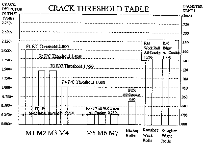
Figure 9 is a bar chart showing threshold signal values for rolls in mill
stands
M 1 to M7, backup rolls, rough worlc rolls, and rougher edger rolls; and
Figure 10 is a schematic exploded view showing a mill roll insert with
manufactured defects and forming part of a test roll for calibration of
nondestructive testing equipment.
Best Mode of Carrying Out the Invention
Mill rolls for use in the metalworking industries are used to produce flat
rolled
and shaped metal products. Mill rolls come in a variety of sizes and shapes
according to the product being made and are useful for continuous operations
for various lengths of time. Periodically, they are removed from service and
maintained using a roll grinding machine generally indicated in Figure 1 by
reference numeral 10. The roll grinding machine 10 is used to return the rolls
to their specified condition, and remove any surface defects after inspecting
the rolls for damage. The roll grinding machine 10 accommodates a roll 1,
CA 02696903 2010-03-19
WO 02/50523 PCT/CA01/01795
-9-
which is driven by motors on a horizontal axis 2. The grinding machine 10 is
normally controlled by a manual or automatic system 3 that powers and
manipulates a grinding wheel 4 that is used to remove material from the roll.
The grinding machine is mounted on a steel base 6 while the roll 1 is
supported on steady rests 7. A system of calipers and test heads (5,8) is used
to measure the dia.ineter of the roll along its axis and to test the surface
and
interior of the roll for cracks and other types of defects commonly found in
mill rolls. The results of the inspection are generally displayed on a
conlputer
screen, cha.t-t recorder or via a number of indicator lights 9.
The benefits of a comprehensive Roll Defect Management Process 24 in
accordance with the invention are outlined in Figure 2. With various inputs
provided by Roll Testing Equipment 21 (including eddy cu.irent testing or
ultrasonic testing), Roll History Data 22 (from various types and lcinds of
databases), and Mill History Data 23 (including mill control systems,
computers and databases), the Roll Defect Management Process 24 provides
benefits as noted, including thorough and detailed roll performance
evaluations 25, cooperative vendor technology development 26, improvements
in mill equipment and operation resulting in a more stable operations 27,
assessment of various procurement initiatives 28, and most iniportant - the
inlprovement of the finished product quality 29. All of these benefits lead to
significant cost savings for the operation.
As mill rolls are the chief tool in the operation of rolling mills, their use
is
subject to many effects. During its service life (which can span a few months
or up to many years) , a mill roll is exposed to high stress, heat, impacts
and
other causes which damage the rolls and which cause strip marks and other
CA 02696903 2010-03-19
WO 02/5, 0523 PCT/CA01/01795
-10-
defects which adversely affect the quality of the flat rolled metal strip
product.
In addition, a variety of defects may be present in the roll inherent to the
inanufacturing process. These may not be detected until the useful shell of
the
roll has been partially consumed. These defects include: cracks, voids,
indentations, variations in microstructure, inclusions, and variations in
hardness. Various nondestructive inspection systems are employed to detect
the presence of such defects, including eddy current and ultrasonic methods.
Eddy currents induced in a roll react to changes in physical properties such
as
changes in the electrical conductivity of the material and test parameters in
the
area under the probes. Filtering and auto-zero circuits reduce the non-defect
responses such as gap variances and temperature. Ultrasound waves react to
changes in the acoustic impedance of the usable shell material of.a roll and
the
bond region of composite roll.
Figure 3 demonstrates a system by which various inputs are used in the Roll
Defect Management Process 24 of Figure 2. Roll History Data identified by
area 22 will include information about a mill roll such as an identification
tag
a.nd the size of the roll, shape, runout and eccentricity, the material of
construction, whether iron or high speed steel, for example, and the
construction type, for example whether it is a composite layered roll or
uniform.
Mill History Data identified by area 23 will include information about rolling
mill operations associated with a roll having a predefined identification tag
such as the mill stand where the roll was used in current and previous
campaigns, the mill operating temperature, a mill output product tag such as
CA 02696903 2010-03-19
WO 02/50523 PCT/CAOI/01795
-11- _
the material, width, and gauge of flat rolled metal strip being produced in
the
current campaign and previous campaigns, and any other data about the mill
operations such as incident reports noting for eYample that strip was held
stationary between rolls possibly causing some localized overheating in the
case of a hot rolling operation. To the extent that such other data may be
collected by manual and visual inspection conducted by operators and is not
automated, such inputs are identified separately in Figure 3 by area 31. These
inputs 22, 23, 31 are used to allow an automatic selection of grinding machine
parameters in an Automatic Control System 34. These paranleters include
setpoints, speeds, feedrates, actions, movements; in short - all aspects of
the
machine control system. This selection is targeted to the specific mill stand,
roll type, and rolling condition, including target quality level and/or
specification. The selection is subsequently output to a computerized numeric
control system (CNC) 36, where the specific steps in the grind activities are
initiated and controlled. These steps include number of rough passes, number
of fnzish passes, and crown/taper/finish passes.
Roll Testing Equipment 21 consisting of eddy current and/or ultrasonic testing
provide additional input data to the selection of grinding machine perameters
in the Automatic Control System 34. Variable amplitude output voltage
signals generated from eddy current or ultrasonic inspection systems are
compared to threshold values and if the comparisons 35 yield positive results,
the roll can be dispositioned for use 38. If the comparisons yield negative
results, the roll must be reground and a new grind program is selected in the
Automatic Control System 34. Various disposition results are possible,
including a supply quality alert which may be automatically generated 39
CA 02696903 2010-03-19
WO 02/50523 PCT/CA01/01795
-12-
where it is determined that the roll has an inherent manufacturing defect and
niust be returned to a supplier.
Before a comparison to threshold values can be made, the nature of a defect in
a mill roll must be classified. In general, the defects which occur in a mill
roll
may be attributed to localized heating for hot rolling operations or to
mechanical impacts or to a combination of these, in additional to any inherent
construction or material defects, or defects caused by improper grinding of
the
rolls.
The localized heat effect from a hot metal strip contacting a roll during an
unscheduled stoppage in a mill will generate thermal cracks in the contact
area
such tliermal cracks are identified by reference numeral 42 in the
photomicrograph of Figure 4. On the roll surface their appearance is similar
to a net and parallel to the centerline. Their internal craclc propagation is
perpendicular to the surface as indicated by reference numeral 51 in the
photomicrograph of Figure 5(a). The length of the crack network is
determined by the width of the metal strip product. Thermal cracks are
typically longer and more open to the surface than pressure cracks. Continued
use of rolls containing thermal cracks can lead to spalls and pitting.
Pressure cracks are generated by local overstressing of the roll material.
Excessive pressure during rolling can be caused by folds in the strip and
incorrect roll chamfers. These craclcs propagate into the roll at angles of
approximately 45 degrees as indicated by reference numera152 in the
photomicrograph of Figure 5(b). Impacts can also cause internal cracks
below the surface and separation of the interface(s) in composite rolls.
CA 02696903 2010-03-19
WO 02/50523 PCT/CA01/01795
-13-
Continued use of rolls with pressure cracks can lead to catastrophic roll
failures.
Metallurgical anomalies from the manufacturer can occur randomly
througliout the usable material on the roll including any interfaces. They can
be any size. A nondestructive surface inspection technique will indicate
changes in hardness due to improper heat treatment or thin shell exposure
prior to the normal roll scrap diameter. Grinding defects may be generated
due to improper procedures and macliine faults.
Pattern Recognition
The Roll Testing Equipment 21 (Fig. 2) is normally carried on an inspection
transport system incorporated into a grinder carriage forming part of the roll
grinding machine 10 (Fig. 1) to ensure 100% coverage of a roll surface while
maintaining a constant probe/roll gap and roll rotational speed as the
inspection system moves along the roll axis. Grinder operators can with
proper training and experience differentiate thermal craclcs from pressure
cracks by visually inspecting an output voltage signal pattern of any defect
locations and comparing the pattern to known defect patterns. The locations
are referenced to the key way position on a roll neck.
A typical analogue pattern of output voltage signals generated from applying
an eddy current voltage to a mill roll having a thermal roll defect is
indicated
by referenced numera141 in Figure 4 adjacent to the corresponding
photomicrograph showing the thermal crack 42.
CA 02696903 2010-03-19
WO 02/50523 PCT/CA01/01795
-14-
A simplified version of a themlal crack defect map is shown in Figure 6.
Thermal (firecracks) cracks can be distinguished by noting the repetitive
spacing between analogue outputs of the detection system in the following
way:
The average peak height Hpa is greater than the noise level Tn by a factor of
3-5 (aka signal to noise ratio).
The pealc width Pw can vary between 0.04 and 0.10 seconds (depending on the
rotational speed of the roll and travel speed of the sensor).
Peak spacing Ps is equal to the roll circumference C divided by the rotation
speed Wr of the roll.
The peak count Pc (number of peaks greater than the noise threshold) is
greater tlian a product width factor N generally corresponding to the widtli
of
flat metal being rolled and the travel speed of the inspection transport
system.
Thermal Crack Definition:
Hpa > K * Tn (K = Signal to noise threshold = 3-5)
Pw = between 0.04 (predetermined time constant ti,) and 0.10 seconds
(predeterniined time constant tiz)
Ps = C/Wr (C= circumference of roll, Wr = speed of roll).
Pc = E Pealcs >Tn, > C/Wr
As will be seen in Figure 4, a new thermal crack appears as a series of
equally
spaced lines in the middle section of the recording and defines a crack defect
map. The areas of the plots representing each end of the roll will not be
affected. The thickness of the lines should not vary more than one line width
and be oriented parallel to the centerline. The previous crack defect map is
compared to the present crack map to determine if the cracks are new or old.
CA 02696903 2010-03-19
WO 02/50523 PCT/CAOI/01795
-15-
A simplified output voltage signal pattern from applying an eddy current
voltage to a mill roll having a mechanical impact craclc is shown in Figure 7.
The craclcs may appear as single line on a plot or may cover 100% of the roll
surface. The pattern is not a series of equally spaced lines and is not
restricted
to the middle section of the roll. The thickness of the lines may vary more
than one line width and the lines are not necessarily oriented parallel to the
centerline. Amplitude or severity values will not decrease significantly with
additional material removal during successive grinding passes. Ultrasound
signals of near surface reflectors at the same location will confirm a
pressure
crack determination. The previous crack defect map is compared to the
present crack map to determine if the craclcs are new mechanical or old
themial craclcs. The retrieval of past roll inspections will show the areas of
old
craclcing. Any new "non-thermal" areas will be considered mechanical.
Mechanical impact cracks may be distinguished from thermal craclcs by noting
the configuration of peaks and random peak spacing in contrast to that
identified for thermal craclcs. The simplified output voltage pattein of
Figure
7 is characterized as follows:
The average peak height Hpa is greater than the noise level by a factor
of 3-5 (aka signal to noise ratio).
The pealc width Pw is less than 0.04 or greater than 0.10 the maximum
time for a thermal crack (The actual value depends on defect size, the
rotational speed of the roll and travel speed of the sensor).
Peak spacing Ps is less than the roll circumference C divided by the
rotation speed Wr of the roll.
CA 02696903 2010-03-19
WO 02/50523 PCT/CA01/01795
-16-
The peak count Pc (peaks greater than the noise threshold) is less than
a product width factor N or constant and is generally less than the
widtll of flat metal product being rolled.
Stress Crack Definition:
Hpa > K * Tn (K = 3-5)
Pw > 0.10 seconds (predetermined tinle constant ti) or Pw < 0.04
(predetermined time constant -r,)
Ps < C/Wr
Pc = F. Peaks >Tn, < N (N= a minimum number of peaks based on
product width)
The appearance of non-thermal roll defects such as grinding defects 82 shown
in the photomicrograph of Figure 8 can vary from a single line to 100% of the
roll surface as shown in a typical pattern 81 of output voltage signals
generated from applying an eddy current voltage to a mill roll and illustrated
by the graphical output of Figure 8. The pattern 81 is different from a new
thermal crack. The previous craclc map is compared to the present crack map
to determine if the cracks are new mechanical or old thermal cracks.
In the case of metallurgical anomalies the appearance of analog signals
plotted
on a graph can vary from a single line to 100% of the roll surface. The
pattern is similar to a pressure craclc. The previous surface inspection
craclc
defect map -is compared to the present crack map to determine if the craclcs
are
new anomalies or old thermal craclcs. The internal inspection map may show
*the depth of the anomalies. A surface inspection bruise map may show if the
anomalies are associated with any new hardness variations or old.
CA 02696903 2010-03-19
WO 02/50523 PCT/CA01/01795
-17-
Acceptance/Rejection Criteria
The goal of the criteria detailed below is to provide rolls without defects
that
will mark the strip or cause roll failures. Roll defect severity is coiTelated
with
surface inspection reports to determine the thermal crack thresholds. Analysis
(dimensions and depth) of the defects initiating the roll failures provides
the
data to determine the internal inspection criteria. The ultrasound inspection
of
new and used rolls provides the data to determine the internal severity
thresliold limits.
In a hot strip mill, rolls containing thermal craclcs are acceptable to use in
early
stands (typically 1 to 4), whereas, in cold rolling mills (tandem mills and
reversing mills) all types of cracks and surface damage must be removed. At
the hot mill, crack severity in the early stands in acceptable ranges does not
marlc a strip. The allowable severity crack rating decreases witli decreasing
roll dianieter. Rolls with more severe cracks may be used in stand one. Any
thernial crack that has an associated near surface internal indication nlust
not
be used. Old thermal cracks with pitting greater than 1 mm width along the
crack length must be repaired to prevent strip marks. Thermal crack severity
decreases with grinding loss. A grinding loss of .040" will produce an
approximate decrease of 1.0 volts in the signal severity.
All pressure cracks inust be removed. Pressure cracks will propagate under
fatigue and result in roll failure or spall causing product marring with
continued mill use. Their severity does not decrease at the same rate as the
thermal craclc severity. This type of crack is deeper and does not readily
change its pattern compared to the thermal crack.
CA 02696903 2010-03-19
WO 02/50523 PCT/CA01/01795
-18-
All grinding defects must be removed. These minor crack defects cause
changes in the surface roughness of the roll and transfer to the strip
surface.
All nletallurgical anomalies must be removed. . Metallurgical anomalies such
as porosity, non-metallic inclusions and hardness variations mark the strip
product from a rolling mill. These defects will appear as pressure craclc
indications on the surface. Poor shell/core interface quality and defects will
lead to roll failures. Ultrasound inspection will detect the near surface, mid-
shell and interface anomalies. Internal reflectors of 1.5" width and conlplete
loss of sound transmission through the roll must not be used. Roll failure
will
result from reflectors with high acoustic impedance. Rolls containing
metallurgical anomalies must be held for evaluation and possible claims
against the manufacturer for poor quality resulting from flaws created during
production of the roll.
Industrial Applicability
Threshold Values
In accordance with the invention, studies are conducted to relate any change
in
the surface and internal inspection system responses to a change in defect
severity. The study produces a relationship between grinding losses and the
change in defect severity. Grinding practices and acceptance/rejection
criteria
are developed to assist an operator in deteimining the disposition of the
roll.
Rolls requiring large losses are routed to designated repair grinders.
The eddy current surface inspection system used by applicant produces a one-
volt change for eveiy forty thousandths of an inch change in grinding loss.
This is a typical relationship for theimal cracks and grinding defects.
Pressure
CA 02696903 2010-03-19
WO 02/50523 PCT/CA01/01795
-19-
craclc and surface anomaly severity do not always follow the above
relationship.
Typical thresholds applicable to mill rolls for a hot mill (volts/severity)
for
crack per stand are shown in Figure 9. Allowable craclc severity decreases as
the roll moves from tandem mill stand one to four (M1 to M4). Rolls used
in stand five to seven (M5 to M7) must be surface defect free and a minimum
crack threshold is maintained at a severity of 0.25 volts. Hardness variations
of 5 points shore "C" must be detected. This change in hardness will mark the
strip.
Internal Indications
An ultrasound flaw detector is calibrated on 5/64" flat bottom hole standards.
Distance amplitude correction is required to display the same severity for the
same defect size at any depth. The amplitude (Y axes) of signal from a flat
bottom hole at the minimum near surface inspection depth is adjusted to
maximum reference value ie.80% screen height at 1.5" depth. Test conditions
are acceptable if the amplitude of the signal from a flat bottom hole at the
maximum inspection depth (deeper than the interface) produces a signal at a
screen height equivalent to the reference value divided by the maximum
depth/minimum depth ratio ie.40% screen height at 3.0" depth. This setup is
for the confirmation of the vertical linearity. Horizontal linearity is set up
by
adjusting the flaw detector controls to make the depth (X axes) indications
appear at the correct distance on the screen. On a five inch range (10
divisions
total) the 1.5" deptli should appear at the third division from the left. The
depth indication from a 3.0" hole should appear at the sixth division.
CA 02696903 2010-03-19
WO 02/50523 PCT/CA01/01795
-20-
The threshold is set for detection of reflectors witll a diaineter 5/12$"(1
mm).
This is a 40 % indication of the possible 100% maximum screen height if
calibrated on a 5/64" flat bottom hole.
Threshold is based on severity and size of reflector. Indications exceeding
the
tlueshold values for the given depth and a minimum dimension of 1.5" will be
rejected. This appears on the video display terminal 9 (Fig. 1) as a 3X3 (0.5"
resolution) highlighted matrix. A variable threshold is used to assist the,
operator to analyze the indications. The maximum indications in the near
surface, sliell and interface zones must be shown for each unit of surface
area
resolved on the VDT, 0.5" minimum resolution.
Roll shop operating practices have been developed by applicant in order to
document and standardize the testing, interpretation and disposition of mill
rolls in the roll grind shop. Various tests can be applied to the roll
including
eddy current tests for surface cracks, magnetism, variations in microstructure
or hardness and voids (also known as round hole defects, spalls, porosity,
etc.)
The defect type, severity, allowable threshold, reaction and disposition is
determined as a result of the test.
Statistical methods can be applied to characterize various crack types
including thermal craclcs (bar firecracks) and mechanical cracks (stress
cracks,
localized overload, impacts). While such a characterization was previously
limited to crack depth, in accordance with the invention, it is now possible
to
additionally distinguish between craclc types by the analysis of the pattern
of
detection equipment signal outputs for example the patterns characterized in
Figure 6 and Figure 7. Once clearly identified, the grinding procedure
CA 02696903 2010-03-19
WO 02/50523 PCT/CA01/01795
-21-
specified for the craclc type can be selected and a minimum amount of material
removed to render the roll useful for the rolling operation without risk of
catastrophic failure in service.
A crack threshold table (Figure 9) has been developed by applicant based on
the specific knowledge gained from the study of many various roll types and
the analysis of many defects found in the mill roll surface through various
non-destructive testing techniques. For each mill stand (M1, M2, M3 ...), roll
type, and specific defect (horizontal axis), the repair amount (vertical axis -
total metal to be removed by grinding or latlie cutting) can be identified and
automatically executed by a machine computerized numeric control system
(CNC) 36 (Figure 3). The voltage pattern from a final inspection of the roll
surface is also compared to the threshold table (Figure 9) and the roll can be
dispositioned for mill use 38, additional grinding, or quarantined 39 for
further
analysis.
The Table of Figure 9 is in the forrn of a bar chart where thresliold signal
values are displayed so as to correspond to the magnitude of output voltage
signals generated by a non-destructive inspection system which are acceptable
for a roll having a predetermined roll history and mill history. As will be
seen
from Figure 9, the threshold for a thermal craclc on a roll in stand Ml is
2.250
volts for an eddy current testing system and is therefore significantly higher
than the threshold of 0.250 volts acceptable for mechanical stress induced
cracics. Accordingly, the depth of material which needs to be removed during
grinding of a roll and shown on the opposing vertical axis to that showing
voltage amplitude is correspondingly less for a roll having an output voltage
CA 02696903 2010-03-19
WO 02/50523 PCT/CA01/01795
-22-
test pattern characteristic of a thermal crack than for a roll where the
output
voltage test pattern characteristic is associated witli a mechanical stress
crack.
Automatic Control System for CNC Grind Program Execution
The Automatic Control System 34 (Figure 3) accepts inputs fiom various.
modules and automation level programs and test equipnlent in order to select a
grinder machine roll maintenance program which is automatically downloaded
to the grind/lathe CNC system 36 for automatic maintenance and preparation
of a mill roll. This is different from current systenis designed and installed
to
date, as grinder/lathe machuie programs normally reside in the machine CNC
code. In accordance with the invention, the CNC code aceepts the selected
grind/latlle program fi-om the higher level (e.g. Level 1/2 system) and
executes
the downloaded program without any operator intervention.
i. Control Data Inputs: Roll History Data 22 and specifications are supplied
from a Leve12 (a.k.a. higher level) automation system. Mill History Data 23
including mill induced daniage from wrecks is supplied from a process control
system. Production.schedule information is received from a Level 2/3 control
systenl(depending on control system hierarchy) identifying requirements for
the next group of products to be manufactured. Roll specifications are
supplied from a Level 1/2 database. Roll inspection data fiom various
detection systems 21 are supplied via CNC/Level 1 inputs. The system will
`self-docunlent' a new roll arriving from manufacture (with a record of `as-
built' internal flaws and/or conditions, shell thickness, material strength),
and
will also be used as pass/fail acceptance criteria of new roll. The system
will
accumulate preliminary grind/inspect data on new rolls for this purpose. A
CA 02696903 2010-03-19
WO 02/50523 PCT/CA01/01795
-23-
summary of control data inputs and a representative example of such inputs
are shown in the following Table 1.
Table 1. CONTROL DATA INPUTS TO HOST MODULE
Various levels and codes are assignable in each category.
Roll Hardness: 850 Ld Internal Con. L2 C Shell Thick: 80
Specification P mm
Mill Data Mill Code: 80 Max Diam: 900 Min. Diam: 700
mm mm
Roll Data Roll No. 232123 Type: HSS C2 Forged
Operating Result Damage: E01 Type: Repair Product: Raised
Spall
Product Schedule Sched #: 12-123 Type: Sp-Light #1 Surface
Required
Roll Use Mill Stand: 01 Position: T Shift Control:
Specification Fixed
Inspection Result T-Crack: H F/C S-Crack: Clear Other: Clear
Product Crown: +.01 mm Tolerance: +0 - Surface: Ra 2.0
Specification .005 in
Other Future Req.
ii. Control Module Application: Control data inputs such as those shown in
Table 1 are processed by the Automatic Control System 34 to select a basic
grind module required for preparation of the roll surface (e.g. reniove wear
profile, remove craclcs to base threshold). The basic grind module is
subsequently modified based on specifications regarding the specific roll type
and its maintenance control plan (e.g. high speed steel rolls type 1 require
additional safety grind to prevent cyclic stress induced fatigue). Further
modifications to the basic grind module are appended based on the
manufacturing requirements of the next production campaign (e.g, the next
products require a specified roll crown numeric profile). The fmal
modification to the basic grind module include fmish surface preparations
(e.g.
CA 02696903 2010-03-19
WO 02/50523 PCT/CA01/01795
-24-
establish roughness as in mill rolls for cold mill tandem mill stand
operations).
The complete grind module is then transferred to the CNC System 36 for
execution.
iii. Automatic Inspection Level: Roll inspection by automatic and manual
metliods is time consuming and unnecessary inspections will result in reduced
productivity in the roll maintenance shop. However, for selected roll types,
extra inspections and special inspections are required to protect against
catastrophic failure in service, or causing roll related defects in the
product
being manufactured. Such data inputs are identified at 31 in Figure 3. Certain
roll types require minimum inspection, depending on the mill stand which is
targeted. An automatic inspection level function in the host program will
assess roll type, mill stand, and product features and specify the required
inspection functions to be initiated by the CNC controls at the grinder/lathe
e.g. wear test; preliminary (fast) defect inspection, current shape test,
final
shape test, final defect inspection, internal defect inspection, and/or other
required inspections. The inspection test sequence and level is added to the
grind module and downloaded to the CNC system 36 for execution.
iv. Intelligent Outputs: An intelligent output includes all typical and common
elements of various CNC control programs for grinders and lathes. In roll
grinders, these are commonly resident within the CNC control system 36 and
must be operator selected and modified to suit the specific roll and its next
application. Also, the results of the tests for roll defects and shape must be
interpreted a.nd then the CNC program must be modified. All of these actions
are managed by the Automatic Control System 34.
CA 02696903 2010-03-19
WO 02/50523 PCT/CA01/01795
-25-
v. Example of Final Grind Program: An example of an output from the
Automatic Control System 36 will include:
Short Strolce (SS) - 10 passes per side ( 0.20 nnn) to remove measured
wear profile
Regular Grind (RG) - 10 - 20 full passes (0.20 mm) to remove residual
Firecracks to required threshold for this roll and next application.
Safety Grind (SG) - 5 full passes (0.01 nun) to remove residual stress,
residual cracks from previous campaigns and/or roll specific safety
margin specified.
Control Grind (CG) - Full passes as required to meet roll profile
specification.
Finish Grind (FG) - 5 full low current passes to control shape, taper
and eccentricity to required specification.
Fiulal Grind (Super Finish Grind/Sparking Out, SFG) - Full passes as
required to control roughness, roll grind mark control.
The above can be summarized as in Table 2, which can be converted by the
host system to CNC code which can be interpreted by the CNC System 36.
(Note above does not include subroutines for inspection which are coded in a
similar manner.)
Table 2. EXAMPLE OF HOST
MACHINE CONTROL CODE OUTPUT
CNC Module Number of Passes Total Metal Removal Specification
SS 10 0.20 0.0
RG 10 0.20 0.0
SG 5 0.01 0.0
CG 0 0 -.001
FG 5 0 -.001
SFG 5 0 -.001
CA 02696903 2010-03-19
WO 02/50523 PCT/CAO]/0179.S
-26-
Test Roll Design
A test roll 101 (shown in Figure 10) is provided to allow calibration and
reliability testing of the roll testing equipment 21 (e.g. Eddy Current,
Ultrasonic, etc). The test roll 101 has a cavity 103 for receiving a specially
designed insert 102 of the appropriate material that ca.n be installed and
removed from a common roll in use at various manufacturing sites. The insert
102 has precision manufactured "defects" 104 comprising line and void
anomalics machined into surface and subsurface locations. These
manufactured defects 104 are factory calibrated and certified as test
standards.
The insert 102 contains various line cracks, at various depths and
configurations. Also, round hole defects are machined at various depths and
in clusters. The test roll 101 is used on site at the grinder or lathe or
other roll
maintenance equipment for the quick and accurate calibration of measurement
and testing equipment.
It will be understood that several variations may be made to the above-
described preferred embodiment of the invention, as will be appreciated by
those skilled in the art.
CA 02696903 2010-03-19
WO 02/50523 PCT/CA01/01795
-27-
Index of Reference Signs
1 Mill roll 101 Test Roll
2 Horizontal axis 102 Insert
3 Grinding machine control system 103 Cavity
4 Grinding wheel 104 Defects
5 Caliper test head
6 Steel base
7 Rests
8 Caliper test head
9 Chart recorder
10 Roll grinding machine
21 Roll testing equipment
22 Roll history data
23 Mill history data
24 Roll defect management process
Roll performance evaluation
26 Cooperative vendor technology development
20 27 Mill stability iniprovements
28 Procurement initiatives
29 Product quality improvements
31 Inputs
25 34 Automatic control system
Comparisons of Output Signals to Control Threshold
36 Coinputerized numeric control
38 Automatic roll disposition
39 Supplier quality alert
41 Output voltage signal
42 Theimal cracks
51 Internal crack propagation
52 Pressure craclcs
81 Output voltage signal
82 Grinding defect