Sélection de la langue

Search

Sommaire du brevet 2697775 

Énoncé de désistement de responsabilité concernant l'information provenant de tiers

Une partie des informations de ce site Web a été fournie par des sources externes. Le gouvernement du Canada n'assume aucune responsabilité concernant la précision, l'actualité ou la fiabilité des informations fournies par les sources externes. Les utilisateurs qui désirent employer cette information devraient consulter directement la source des informations. Le contenu fourni par les sources externes n'est pas assujetti aux exigences sur les langues officielles, la protection des renseignements personnels et l'accessibilité.

Disponibilité de l'Abrégé et des Revendications

L'apparition de différences dans le texte et l'image des Revendications et de l'Abrégé dépend du moment auquel le document est publié. Les textes des Revendications et de l'Abrégé sont affichés :

  • lorsque la demande peut être examinée par le public;
  • lorsque le brevet est émis (délivrance).
(12) Brevet: (11) CA 2697775
(54) Titre français: DOUILLE RENFORCEE LEGERE A ASSEMBLAGE AISE
(54) Titre anglais: LIGHTWEIGHT HEAVY DUTY BUSHING WITH EASY ASSEMBLY
Statut: Périmé et au-delà du délai pour l’annulation
Données bibliographiques
(51) Classification internationale des brevets (CIB):
  • B60G 99/00 (2010.01)
  • B60G 11/12 (2006.01)
(72) Inventeurs :
  • VOGLER, RICHARD GREGORY (Etats-Unis d'Amérique)
  • BRANNIGAN, MICHAEL (Etats-Unis d'Amérique)
  • DUDDING, ASHLEY THOMAS (Etats-Unis d'Amérique)
  • FORREST, CHRISTOPHER WAYNE (Etats-Unis d'Amérique)
(73) Titulaires :
  • HENDRICKSON USA, L.L.C.
(71) Demandeurs :
  • HENDRICKSON USA, L.L.C. (Etats-Unis d'Amérique)
(74) Agent: OSLER, HOSKIN & HARCOURT LLP
(74) Co-agent:
(45) Délivré: 2016-04-19
(86) Date de dépôt PCT: 2008-09-04
(87) Mise à la disponibilité du public: 2009-03-12
Requête d'examen: 2013-08-30
Licence disponible: S.O.
Cédé au domaine public: S.O.
(25) Langue des documents déposés: Anglais

Traité de coopération en matière de brevets (PCT): Oui
(86) Numéro de la demande PCT: PCT/US2008/075226
(87) Numéro de publication internationale PCT: US2008075226
(85) Entrée nationale: 2010-02-24

(30) Données de priorité de la demande:
Numéro de la demande Pays / territoire Date
11/849,731 (Etats-Unis d'Amérique) 2007-09-04

Abrégés

Abrégé français

La présente invention concerne un assemblage de douille renforcée légère destiné à être utilisé dans un système de suspension de véhicule, qui est peu coûteux et qui possède de hautes tolérances d'assemblage. Une tige métallique est ajustée avec serrage dans une douille formée à partir d'un manchon métallique lié à un logement élastomère. Le manchon métallique est déformable de sorte que des tolérances exactes du manchon métallique et de la tige ne soient pas nécessaires. La tige métallique comporte des extrémités étendues avec un orifice dans chaque extrémité pour la fixation de la tige à des composants de suspension de véhicule, des supports de montage, ou au châssis de véhicule.


Abrégé anglais


A lightweight heavy duty bushing assembly for use
in a vehicle suspension system and being low cost and having a high
assembly tolerance is disclosed. A metal bar pin is press fit into a
bushing formed from a metal sleeve bonded to an elastomeric
housing. The metal sleeve is deformable such that exact tolerances of the
metal sleeve and the bar pin are not required. The metal bar pin has
extended ends with a hole in each end for attachment of the metal bar
pin to vehicle suspension components, mounting brackets, or to the
vehicle frame.

Revendications

Note : Les revendications sont présentées dans la langue officielle dans laquelle elles ont été soumises.


The embodiments of the present invention for which an exclusive property or
privilege is claimed
are defined as follows:
1. A vehicle suspension bushing assembly comprising:
a deformable metal vehicle suspension sleeve having an inner diameter;
an elastomeric vehicle suspension housing secured to an outer surface of said
deformable metal vehicle suspension sleeve; and
a metal vehicle suspension bar pin press fit into said deformable metal
vehicle
suspension sleeve, wherein the metal vehicle suspension bar pin comprises a
central section
and an end portion extending beyond each end of the central section,
the central section of the metal vehicle suspension bar pin includes a
plurality of radially extending contact surfaces which bear against the inner
diameter of the deformable metal vehicle suspension sleeve,
the metal vehicle suspension bar pin has a greater outer diameter at the
contact surfaces than at any other portion, and
the outer diameter of the contact surfaces is greater than or substantially
equal to the inner diameter of the deformable metal vehicle suspension sleeve.
2. The vehicle suspension bushing assembly of claim 1 wherein said
elastomeric vehicle
suspension housing is bonded to said deformable metal vehicle suspension
sleeve.
3. The vehicle suspension bushing assembly of claim 1 wherein said metal
vehicle suspension
bar pin has a central section with four contact surfaces.
4. The vehicle suspension bushing assembly of claim 3 wherein two of the
contact surfaces
are in full contact with said deformable metal vehicle suspension sleeve and
two of the contact
surfaces are only in line contact with the deformable metal vehicle suspension
sleeve.
8

5. The vehicle suspension bushing assembly of claim 1 wherein said metal
vehicle suspension
bar pin has a central section with three contact surfaces.
6. The vehicle suspension bushing assembly of claim 1 wherein said metal
vehicle suspension
bar pin has a central section with five contact surfaces.
7. The vehicle suspension bushing assembly of claim 1 wherein said metal
vehicle suspension
bar pin has a central section with six contact surfaces.
8. The vehicle suspension bushing assembly of claim 1 wherein the end
portions of said metal
vehicle suspension bar pin extend beyond each end of said deformable metal
vehicle suspension
sleeve.
9. The vehicle suspension bushing assembly of claim 1 wherein each of said
end portions of
said metal vehicle suspension bar pin has a hole through it.
10. The vehicle suspension bushing assembly of claim 1 wherein said
deformable metal
vehicle suspension sleeve is circular in cross section.
11. The vehicle suspension bushing assembly of claim 1 wherein said
deformable metal
vehicle suspension sleeve is non-circular in cross section.
12. The vehicle suspension bushing assembly of claim 1 wherein the central
section of said
metal vehicle suspension bar pin is comprised of voids bounded by the radially
extending contact
surfaces.
13. A method of assembling said vehicle suspension bushing assembly of
claim 1 by press
fitting said metal vehicle suspension bar pin into said deformable inner metal
vehicle suspension
sleeve.
14. The vehicle suspension bushing assembly of claim 1 wherein the
deformable metal vehicle
suspension sleeve has a length substantially equal to the length of the
contact surfaces of the metal
vehicle suspension bar pin.
9

15. The vehicle suspension bushing assembly of claim 1 wherein at least one
of the contact
surfaces is differently shaped than another one of the contact surfaces.
16. The vehicle suspension bushing assembly of claim 1 wherein a greater
portion of one of
the contact surfaces bears against the deformable metal vehicle suspension
sleeve than another one
of the contact surfaces.
17. A vehicle suspension bushing assembly consisting of:
a deformable metal vehicle suspension sleeve having an inner diameter;
an elastomeric vehicle suspension housing secured to an outer surface of said
deformable
metal vehicle suspension sleeve; and
a metal vehicle suspension bar pin press fit into said deformable metal
vehicle suspension
sleeve, wherein
the metal vehicle suspension bar pin comprises a central section and an end
portion
extending beyond each end of the central section,
the central section of the metal vehicle suspension bar pin includes a
plurality of
radially extending contact surfaces which bear against the inner diameter of
the deformable
metal vehicle suspension sleeve,
the metal vehicle suspension bar pin has a greater outer diameter at the
contact
surfaces than at any other portion, and
the outer diameter of the contact surfaces is greater than or substantially
equal to
the inner diameter of the deformable metal vehicle suspension sleeve.
18. A vehicle suspension mountable to a vehicle frame comprising:
a plurality of suspension components;
a plurality of mounting brackets; and

a vehicle suspension bushing assembly comprising
a deformable metal vehicle suspension sleeve having an inner diameter;
a vehicle suspension housing secured to an outer surface of said deformable
metal
vehicle suspension sleeve; and
a metal vehicle suspension bar pin press fit into said deformable metal
vehicle
suspension sleeve, wherein at least a portion of the outermost surface of the
vehicle
suspension bushing assembly is comprised of an elastomeric material,
the metal vehicle suspension bar pin comprises a central section and an end
portion extending beyond each end of the central section,
the central section of the metal vehicle suspension bar pin includes a
plurality of radially extending contact surfaces which bear against the inner
diameter of the deformable metal vehicle suspension sleeve,
the metal vehicle suspension bar pin has a greater outer diameter at the
contact surfaces than at any other portion,
the outer diameter of the contact surfaces is greater than or substantially
equal to the inner diameter of the deformable metal vehicle suspension sleeve,
and
the vehicle suspension bushing assembly is attached to one of said plurality
of suspension components, one of said plurality of mounting brackets, and/or
said
vehicle frame.
19. The
vehicle suspension of claim 18, wherein each end portion of the metal vehicle
suspension bar pin includes a hole for attaching the vehicle suspension
bushing assembly to one
of said plurality of suspension components, one of said plurality of mounting
brackets, and/or said
vehicle frame.
11

20. The
vehicle suspension of claim 18, wherein one of said plurality of suspension
components comprises a torque rod, the vehicle suspension bushing assembly
being inserted into
the torque rod.
12

Description

Note : Les descriptions sont présentées dans la langue officielle dans laquelle elles ont été soumises.


CA 02697775 2010-02-24
WO 2009/032906
PCT/US2008/075226
PATENT
Attorney Docket: 0715-0179
LIGHTWEIGHT HEAVY DUTY BUSHING WITH EASY ASSEMBLY
DESCRIPTION
Background of the Invention
[001] The present invention is generally directed to bushing assemblies in
vehicle
suspension systems. More specifically, the present invention is directed to a
unique
construction of bushing assemblies used in vehicle suspension systems.
[002] Vehicle suspension bushing assemblies are known. One such bushing
assembly may be formed from a round inner metal bar pin that is an elongated
piece of
metal such as cast iron which is contained within a combination of a circular
metal sleeve
attached to an elastomeric material such as rubber. The circular metal sleeve
and the
round bar pin must be machined to very exact tolerances to properly fit
together. The
increased machining and processing of the components due to the required low
tolerances
increases costs. The circular bar pin may be heavy, which leads to increased
material,
manufacturing and shipping costs.
[003] Another known bushing assembly may be formed from a round inner metal
bar pin that is a machined length of metal such as aluminum that is bonded
directly to an
elastomeric material such as rubber. The direct bonding of the rubber to the
inner metal
bar pin requires specific types of metal and additional machining or
processing to yield a
proper bond between the inner metal and the rubber, thus increasing costs.
[004] The combined inner metal bar pin bonded to a rubber bushing may also
be
inserted into a metal sleeve to form another known bushing assembly. The
bushing
assembly may have attachment means on both ends of the inner metal bar pin.
[005] While prior vehicle suspension bushing assemblies have been adequate
for
certain purposes, they have lacked some of the advantages obtainable with the
embodiments of the present invention. Many of these advantages are clearly
described
herein and others shall be readily apparent to those skilled in the art.
[006] One advantage achieved by the present invention is the use of a
deformable
metal sleeve into which the metal bar pin is press fit.

CA 02697775 2010-02-24
WO 2009/032906
PCT/US2008/075226
[007] Another advantage achieved by the present invention is by the use of
low cost
steel tube for the metal sleeve.
[008] Another advantage achieved by the present invention is the use of an
as-cast
or near as-cast ductile inner metal bar pin that requires little or no
machining or
processing.
[009] Another advantage achieved by the present invention is the lower
costs
achieved by the need for little or no machining of the inner metal bar pin.
[0010] Another advantage achieved by the present invention is the use of an
inner
metal bar pin with a non-circular cross section that has voids bounded by
radially
extending contact portions.
[0011] Another advantage achieved by the present invention is the lower
cost of the
reduced weight achieved by the use of an inner metal bar pin with a non-
circular cross
section with voids.
[0012] Another advantage achieved by the present invention is the lower
cost of the
reduced material required by the use of an inner metal bar pin with a non-
circular cross
section with voids.
[0013] Another advantage achieved by the present invention is the use of
ductile cast
iron for the metal bar pin.
10014] Another advantage achieved by the present invention is the use of a
process to
insert the metal bar pin into the metal sleeve and rubber combination and to
insert the
resulting bushing assembly into a vehicle suspension component such as a
torque rod in a
single press fit operation.
100151 Another advantage achieved by the present invention is by allowing
the steel
tube to deform into a non-circular shape during the press fit operation
instead of requiring
a precise tolerance to fit a uniform circular metal sleeve.
[0016] Another advantage achieved by the present invention is by
controlling the
amount of the steel tube deformation such that the bond line with the rubber
component
is not compromised.
[00171 Another advantage achieved by the present invention is designing a
cruciform
embodiment such that the press fit between the crucifoim and the steel tube
sleeve has
2

CA 02697775 2010-02-24
WO 2009/032906
PCT/US2008/075226
two cruciform extension end surfaces in full contact with the steel tube and
two cruciform
extension end surfaces in only a line contact with the steel tube.
100181 These and other advantages of the preferred forms of the invention
will
become apparent from the following description. It will be understood,
however, that an
apparatus could still appropriate the invention claimed herein without
exhibiting each and
every one of these advantages, including those gleaned from the following
description.
The appended claims, not any advantages recited or implied herein, define the
subject
matter of this invention. Any and all advantages are derived from the
preferred forms of
the invention, not necessarily the invention in general.
Summary of the Invention
[00191 The present invention is directed to a vehicle suspension bushing
assembly. A
bushing assembly has a ductile inner metal bar pin with a center section
having an
optimized non-circular cross section with voids for maximum strength at
minimum
weight. The ductile inner metal bar pin has an extended end section on each
side of the
center section. Each extended end section of the ductile inner metal bar pin
has a hole for
means of attachment to other suspension components, mounting brackets, or to
the
vehicle flame. The ductile inner metal bar pin is press fit into a bushing
comprised of an
elastomeric material housing such as rubber bonded or otherwise secured to a
metal
sleeve such as a defonnable steel tube. The resulting deformable steel tube
after the press
fit operation has a cross section that is non-circular. The press fit assembly
has adequate
frictional force such that the inner metal bar pin does not translate within
the metal sleeve
under service duty.
100201 The present invention also allows the inner metal bar pin to be
press fit into
the metal sleeve and rubber bushing and to insert the entire bushing assembly
into a
vehicle suspension component such as a torque rod in a single one step
operation.
[0021] In addition, other built-in features are available with the present
invention.
3

CA 02697775 2015-05-04
Brief Description of the Drawings
[0022] In the following detailed description, reference will frequently be
made to the
following drawings, in which like reference numerals refer to like components,
and in
which:
[0023] FIG. 1 is a perspective view of a lightweight heavy duty bushing
assembly
constructed in accordance with the principles of-the present invention;
[0024] FIG. 2 is a side elevational view of the bushing assembly shown in
FIG. 1;
[0025] FIG. 3 is an end view of the bushing assembly shown in FIG. 1; =
[0026] FIG. 4 is a top view of the bushing assembly shown in FIG. 1;
[0027] FIG. 5 is a perspective view of part of the bushing assembly shown
in FIG. 1;
[0028] FIG. 6 is a side elevations] view of the bushing shown in FIG. 5;
[0029] FIG. 7 is an end view of the bushing shown in FIG. 5;
[0030] FIG. 8 is a perspective view of an embodiment of a four point bar
pin having a
cruciform cross section constructed in accordance with the principles of the
present
invention;
[0031] FIG. 9 is a side elevational view of the bar pin shown in FIG. 8;
[0032] FIG. 10 is an end view of the bar pin shown in FIG. 8;
[0033] FIG. 11 is a sectional view of part of a=bushing assembly having a
three point
alternative embodiment of a bar pin;
[0034] FIG. 12 is a sectional view of part of a bushing assembly having a
five point
alternative embodiment of a bar pin;
[0035] FIG. 13 is a sectional view of part of a bushing assembly having a
six point
alternative embodiment of a bar pin;
[0036] FIG. 14 is an end view of the bushing assembly shown in FIG. 1
better
showing the as assembled condition; and
[0037] FIG. 15 is an end view similar to FIG. 14 better showing further
details of a
preferred as assembled condition.
10037a1 Fig. 16 is a
perspective view of a vehicle suspension incorporating
bushing assemblies according to the present disclosure.
4

CA 02697775 2010-02-24
WO 2009/032906 =
PCT/US2008/075226
Detailed Description of the Preferred Embodiments
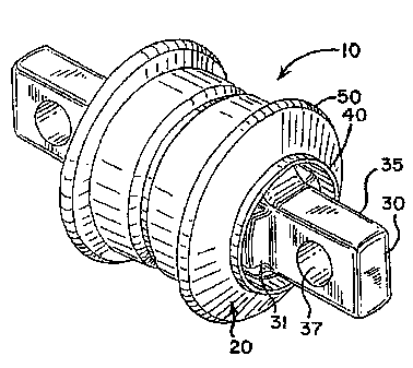
= [00381 FIGS. 1-4 illustrate a lightweight heavy duty bushing
assembly 10 for vehicle
suspensions. A ductile inner metal bar pin 30 is press fit into a bushing 20.
The ductile
inner metal bar pin 30 has a central portion 31 with a cruciform cross-section
that is
comprised of voids 32 bounded by radially extending contact surfaces 33. The
ductile
inner metal bar pin 30 has an end portion 35 that extends beyond each end of
the central
portion 31. Each extended end portion 35 of the ductile inner metal bar pin 30
has a hole
37 through it for attachment to vehicle suspension components, mounting
brackets, or to
the vehicle frame (not shown). The ductile inner metal bar pin 30 is
preferably cast of
metal material, such as iron. Alternatively, the ductile inner metal bar pin
30 could be
cast from other materials or the ductile inner metal bar pin 30 could be
forged or
machined from a variety of materials.
[0039] The bushing 20 is comprised of a metal sleeve 40 that is attached
such as by
bonding to an elastomeric housing 50 such as rubber. The elastomeric housing
50 is
shaped to the desired dimensions by a process such as molding. The metal
sleeve 40 may
be made of a deformable meal such as steel.
[0040] FIGS. 5-7 illustrate an embodiment of the bushing 20. As previously
noted,
the bushing 20 may be comprised of a metal sleeve 40 that is bonded to an
elastomeric
housing 50. Alternatively, the entire bushing 20 may be formed from a single
material by
a process such as casting or molding. The cross section of the metal sleeve 40
prior to
receiving the ductile inner metal bar pin 30 is generally circular as shown in
FIG. 7.
[0041] FIGS. 8-10 illustrate an embodiment of the ductile inner metal bar
pin 30. The
ductile inner metal bar pin 30 has a central section with a four point or
cruciform shape as
shown in FIG. 10. The cross section of the ductile inner metal bar pin 30 is
optimized to
reduce weight and improve structural efficiency. The holes 37 in the extended
end
portions 35 of the ductile inner metal bar pin 30 are sized and positioned to
provide
appropriate means to attach the ductile inner metal bar pin 30 to vehicle
suspension
components or to the vehicle frame while maximizing the strength of the
ductile inner
metal bar pin 30.

CA 02697775 2010-02-24
WO 2009/032906
PCT/US2008/075226
[0042] FIG. 11 illustrates a three point embodiment of the central section
of a ductile
inner metal bar pin 60 comprised of voids 32 bounded by radially extending
contact
surfaces 33 within a metal sleeve 40. The cross section of the ductile inner
metal bar pin
60 is optimized to reduce weight and improve structural efficiency.
[0043] FIG. 12 illustrates a five point embodiment of the central section
of a ductile
inner metal bar pin 70 comprised of voids 32 bounded by radially extending
contact
surfaces 33 within a metal sleeve 40. The cross section of the ductile inner
metal bar pin
70 is optimized to reduce weight and improve structural efficiency.
[0044] FIG. 13 illustrates a six point embodiment of the central section of
a ductile
inner metal bar pin 80 comprised of voids 32 bounded by radially extending
contact
surfaces 33 within a metal sleeve 40. The cross section of the ductile inner
metal bar pin
80 is optimized to reduce weight and improve structural efficiency.
[0045] It is to be understood that FIGs. 11-13 are partial figures of the
entire bushing
assembly and that the embodiments illustrated in FIGs. 11-13 also contain an
elastomeric
housing bonded or otherwise secured to the metal sleeve.
100461 FIG, 14 illustrates an embodiment of a lightweight heavy duty
bushing
assembly 10 where the press fit of the ductile inner metal bar pin 30 caused
the metal
sleeve 40 to deform from a circular cross section to a non-circular cross
section, thus
enabling a high tolerance between the components for assembly.
FIG. 15 illustrates another embodiment of the lightweight heavy duty bushing
assembly
shown in FIG. 14. Two of the cruciform extension end surfaces 38 are in fidl
contact
with the metal sleeve 40 and the other two cruciform extension end surfaces 39
make
only a line contact with the metal sleeve 40. The ductile inner metal bar pin
30 is
therefore structurally efficient in that the metal material is concentrated
where it is
needed to react to torque rod loads. Looser tolerances are thus permitted on
the inner
diameter of the metal sleeve 40 and the outer surfaces of the cruciform
extension end
surfaces 38, 39 allowing for easier assembly of the ductile inner metal bar
pin 30 into the
metal sleeve 40. Frictional forces between the ductile inner metal bar pin 30
and the
metal sleeve 40 prevent translation of the ductile inner metal bar pin 30
within the metal
sleeve 40 while under service duty or operation.
6

CA 02697775 2015-05-04
[0046a] Fig. 16 shows an exemplary vehicle suspension 100 which may employ
bushing
assemblies according to the present disclosure. The vehicle suspension 100 of
Fig. 16
includes, among other things, a plurality of torque rods 102 each connected at
one end to
an axle or air spring bracket 104 and at the other end to a mounting bracket 1
06. An upper
end of each mounting bracket 106 is fastened to the vehicle frame 108, thereby
securing the
vehicle suspension 100 to the vehicle frame 108. In the illustrated
embodiment, each end of
the torque rods 102 is provided with a bore into which a bushing assembly 10
according to
the present disclosure may be inserted. The holes 37 at the end portions 35 of
the inner metal
bar pins 30 (Fig. 1) may receive fasteners or the like to secure each bushing
assembly 10
(and, hence, the associated end of the torque rod 102) to an axle bracket 104
or mounting
bracket 106
[0047] The scope of the claims should not be limited by the preferred
embodiments set
forth in the examples, but should be given the broadest interpretation
consistent with the
Description as a whole.
7

Dessin représentatif
Une figure unique qui représente un dessin illustrant l'invention.
États administratifs

2024-08-01 : Dans le cadre de la transition vers les Brevets de nouvelle génération (BNG), la base de données sur les brevets canadiens (BDBC) contient désormais un Historique d'événement plus détaillé, qui reproduit le Journal des événements de notre nouvelle solution interne.

Veuillez noter que les événements débutant par « Inactive : » se réfèrent à des événements qui ne sont plus utilisés dans notre nouvelle solution interne.

Pour une meilleure compréhension de l'état de la demande ou brevet qui figure sur cette page, la rubrique Mise en garde , et les descriptions de Brevet , Historique d'événement , Taxes périodiques et Historique des paiements devraient être consultées.

Historique d'événement

Description Date
Le délai pour l'annulation est expiré 2020-09-04
Représentant commun nommé 2019-10-30
Lettre envoyée 2019-09-04
Accordé par délivrance 2016-04-19
Inactive : Page couverture publiée 2016-04-18
Préoctroi 2016-02-09
Inactive : Taxe finale reçue 2016-02-09
Un avis d'acceptation est envoyé 2015-09-17
Lettre envoyée 2015-09-17
Un avis d'acceptation est envoyé 2015-09-17
Requête visant le maintien en état reçue 2015-09-01
Inactive : Approuvée aux fins d'acceptation (AFA) 2015-08-05
Inactive : Q2 réussi 2015-08-05
Modification reçue - modification volontaire 2015-05-04
Inactive : Dem. de l'examinateur par.30(2) Règles 2014-11-03
Inactive : Rapport - Aucun CQ 2014-10-30
Inactive : Demande ad hoc documentée 2014-10-30
Inactive : Lettre officielle 2014-10-30
Inactive : Dem. de l'examinateur par.30(2) Règles 2014-10-23
Inactive : CIB attribuée 2014-10-17
Inactive : Rapport - CQ réussi 2014-10-17
Requête visant le maintien en état reçue 2014-09-04
Lettre envoyée 2013-09-09
Toutes les exigences pour l'examen - jugée conforme 2013-08-30
Exigences pour une requête d'examen - jugée conforme 2013-08-30
Requête d'examen reçue 2013-08-30
Lettre envoyée 2011-07-20
Inactive : CIB enlevée 2010-05-14
Inactive : CIB en 1re position 2010-05-14
Inactive : CIB attribuée 2010-05-14
Inactive : Page couverture publiée 2010-05-11
Inactive : Notice - Entrée phase nat. - Pas de RE 2010-05-06
Demande reçue - PCT 2010-04-29
Inactive : CIB attribuée 2010-04-29
Inactive : CIB en 1re position 2010-04-29
Exigences pour l'entrée dans la phase nationale - jugée conforme 2010-02-24
Demande publiée (accessible au public) 2009-03-12

Historique d'abandonnement

Il n'y a pas d'historique d'abandonnement

Taxes périodiques

Le dernier paiement a été reçu le 2015-09-01

Avis : Si le paiement en totalité n'a pas été reçu au plus tard à la date indiquée, une taxe supplémentaire peut être imposée, soit une des taxes suivantes :

  • taxe de rétablissement ;
  • taxe pour paiement en souffrance ; ou
  • taxe additionnelle pour le renversement d'une péremption réputée.

Les taxes sur les brevets sont ajustées au 1er janvier de chaque année. Les montants ci-dessus sont les montants actuels s'ils sont reçus au plus tard le 31 décembre de l'année en cours.
Veuillez vous référer à la page web des taxes sur les brevets de l'OPIC pour voir tous les montants actuels des taxes.

Historique des taxes

Type de taxes Anniversaire Échéance Date payée
Taxe nationale de base - générale 2010-02-24
TM (demande, 2e anniv.) - générale 02 2010-09-07 2010-08-25
Enregistrement d'un document 2011-06-30
TM (demande, 3e anniv.) - générale 03 2011-09-06 2011-08-30
TM (demande, 4e anniv.) - générale 04 2012-09-04 2012-08-31
TM (demande, 5e anniv.) - générale 05 2013-09-04 2013-08-28
Requête d'examen - générale 2013-08-30
TM (demande, 6e anniv.) - générale 06 2014-09-04 2014-09-04
TM (demande, 7e anniv.) - générale 07 2015-09-04 2015-09-01
Taxe finale - générale 2016-02-09
TM (brevet, 8e anniv.) - générale 2016-09-06 2016-08-29
TM (brevet, 9e anniv.) - générale 2017-09-05 2017-08-28
TM (brevet, 10e anniv.) - générale 2018-09-04 2018-09-04
Titulaires au dossier

Les titulaires actuels et antérieures au dossier sont affichés en ordre alphabétique.

Titulaires actuels au dossier
HENDRICKSON USA, L.L.C.
Titulaires antérieures au dossier
ASHLEY THOMAS DUDDING
CHRISTOPHER WAYNE FORREST
MICHAEL BRANNIGAN
RICHARD GREGORY VOGLER
Les propriétaires antérieurs qui ne figurent pas dans la liste des « Propriétaires au dossier » apparaîtront dans d'autres documents au dossier.
Documents

Pour visionner les fichiers sélectionnés, entrer le code reCAPTCHA :


Pour visualiser une image, cliquer sur un lien dans la colonne description du document. Pour télécharger l'image (les images), cliquer l'une ou plusieurs cases à cocher dans la première colonne et ensuite cliquer sur le bouton "Télécharger sélection en format PDF (archive Zip)" ou le bouton "Télécharger sélection (en un fichier PDF fusionné)".

Liste des documents de brevet publiés et non publiés sur la BDBC .

Si vous avez des difficultés à accéder au contenu, veuillez communiquer avec le Centre de services à la clientèle au 1-866-997-1936, ou envoyer un courriel au Centre de service à la clientèle de l'OPIC.


Description du
Document 
Date
(aaaa-mm-jj) 
Nombre de pages   Taille de l'image (Ko) 
Dessins 2010-02-23 3 155
Abrégé 2010-02-23 1 65
Description 2010-02-23 7 369
Revendications 2010-02-23 2 60
Dessin représentatif 2010-05-06 1 13
Dessins 2015-05-03 4 152
Revendications 2015-05-03 5 155
Description 2015-05-03 7 365
Dessin représentatif 2015-08-03 1 12
Dessin représentatif 2016-02-29 1 18
Rappel de taxe de maintien due 2010-05-05 1 113
Avis d'entree dans la phase nationale 2010-05-05 1 195
Rappel - requête d'examen 2013-05-06 1 126
Accusé de réception de la requête d'examen 2013-09-08 1 176
Avis du commissaire - Demande jugée acceptable 2015-09-16 1 162
Avis concernant la taxe de maintien 2019-10-15 1 177
PCT 2010-02-23 1 46
Correspondance 2010-03-23 2 65
Taxes 2011-08-29 1 44
Taxes 2014-09-03 1 44
Correspondance 2014-10-29 1 22
Paiement de taxe périodique 2015-08-31 1 42
Taxe finale 2016-02-08 1 44