Note : Les descriptions sont présentées dans la langue officielle dans laquelle elles ont été soumises.
CA 02699330 2012-07-24
METHOD AND APPARATUS FOR WELL-BORE PROXIMITY
MEASUREMENT WHILE DRILLING
BACKGROUND OF THE DISCLOSURE
1. Field of the Disclosure
[0001] This disclosure relates generally to methods for performing measurement
while drilling applications. More particularly, this disclosure relates to a
new and
improved apparatus and method for determining a distance to a pre-existing
wellbore
and controlling drilling operations based on the determination.
2. Background of the Art
[0002] In the process of drilling wells for hydrocarbon production, it is
commonly
necessary to drill a second well in a predetermined relationship to an
existing well.
An example of this may be when a blowout occurred in the existing well; two
approaches may be taken to control the blowout. One method is to use
explosives at
the surface and snuff out the fire in the burning well. This procedure is
fraught with
danger and requires prompt control of hydrocarbons flow in the well. The
second
method is to drill a second borehole to intersect the blowout well and pump
drilling
mud into the blowout well. This is not a trivial matter. An error of half a
degree can
result in a deviation of close to 90 feet at a depth of 10,000 feet. A typical
borehole is
about 12 inches in diameter, a miniscule target compared to the potential
error zone.
[0003] Another situation in which accurate drilling is required is in
secondary
recovery operations. For various reasons, such as low formation pressure or
high
viscosity of hydrocarbons in the reservoir, production under natural
conditions of
hydrocarbons may be at uneconomically low rates. In such cases, a second
borehole
is drilled to be substantially parallel to the pre-existing borehole. Fluid
such as water,
CO2 is then injected into the formation from the second borehole and the
injected
CA 02699330 2010-03-11
WO 2009/029850
PCT/US2008/074871
fluid drives the hydrocarbons in the formation towards the producing borehole
where
it may be recovered.
[0004] In 1970, Shell Oil Co.'s Cox 1, a 22,000-ft Smackover exploratory well,
blew
out near Piney Woods, Mississippi. This challenge led to the first direct
intersection
of a blowout tubular using an acoustic detection method. Wireline instruments
were
developed to detect proximity of a tubular by measuring distance and direction
from
the relief well to the blowout casing using the noise from the flowing gas in
the
blowout well. More recently, electromagnetic methods have been used to
determine
the distance to the cased preexisting well.
[0005] The electromagnetic techniques fall into 2 categories. In the first
category,
referred to as active ranging, a source of AC magnetic field and a magnetic
sensor are
placed in different wells. The source can be a solenoid placed in the
production well
or an electric current injected in the production well casing. The magnetic
field
produced by the current in the casing is measured in the drilling well. The
active
ranging approach can probably offer a good accuracy of measurements, but
suffers
from the drawback that access to the pre-existing well is required.
[0006] In the second category are passive ranging techniques that do not
require
access to the pre-existing well while drilling the second well. The techniques
normally utilize a relatively strong magnetism induced in the casing of the
pre-
existing well by the Earth's magnetic field. The signal due directly to the
earth's
magnetic field is a problem, limiting the accuracy of this measurement.
Residual
magnetism of the casing introduces additional uncertainties. The following US
patents
reflect some of the techniques proposed and used for magnetic ranging:
4,323,848 to
Kuckes; 4,372,398 to Kuckes ; 4,443,762 to Kuckes; 4,529,939 to Kuckes;
4,700,142
to Kuckes; 4,791,373 to Kuckes; 4,845,434 to Kuckes ; 5,074,365 to Kuckes;
5,218,301 to Kuckes ; 5,305,212 to Kuckes; 5,343,152 to Kuckes 5,485,089 to
Kuckes; 5,512,830 to Kuckes ; 5,513,710 to Kuckes; 5,515,931 to Kuckes ;
5,675,488
2
CA 02699330 2010-03-11
WO 2009/029850
PCT/US2008/074871
to McElhinney; 5,725,059 to Kuckes et al.; 5,923,170 to Kuckes; 5,657,826 to
Kuckes; 6,937,023 to McElhinney; and 6,985,814 to McElhinney.
[0007] The present disclosure teaches a method in which access to the pre-
existing
well is not required and the effects of the direct earth's magnetic field are
minimized.
SUMMARY OF THE DISCLOSURE
[0008] One embodiment of the disclosure is a method of determining a distance
to a
first borehole from a second borehole. A time varying magnetic field is
produced in
the first borehole using a magnet in the second borehole. Magnetization in a
magnetic
object in the first borehole is produced. A coil in the second borehole is
used to
produce a signal responsive to a magnetic flux resulting from the
magnetization. This
signal is used to estimate the distance. The magnetic object in the first
borehole may
be a casing. The method may further include using the estimated distance to
maintain
a trajectory of the second borehole in a desired relation to the first
borehole. The
desired relation may be substantially parallel or intersecting. The method may
include conveying a magnet on a bottomhole assembly on a drilling tubular into
the
second borehole. Producing a time varying field may be done rotating a magnet
having a substantially transverse magnetization in the second borehole at a
first
rotational speed, and producing the signal may be done by rotating the coil
synchronously with the magnet. Estimating the distance may further include
filtering
of the signal to remove an effect of a magnetic field of the earth. The method
may
further include measuring the first rotational speed, determining a second
harmonic
component of the first rotational speed, and using the determined second
harmonic
component to correct the signal. The method may further include measuring an
additional signal using a split coil responsive to the magnetic flux, and
using the
additional signal as an indicator of an inclination between an axis of the
first borehole
and an axis of the second borehole. The first rotational speed may be
substantially the
same as a rotational speed of a bottomhole assembly. The time varying field
may be
produced by switching a polarity of a magnet having a substantially
longitudinal
3
CA 02699330 2010-03-11
WO 2009/029850
PCT/US2008/074871
magnetization in the second borehole, and producing the signal may be done
using a
coil with an axis that is substantially longitudinal.
[0009] Another embodiment of the disclosure is an apparatus for determining a
distance in a first borehole from a second borehole. The apparatus includes a
magnet
configured to be conveyed in a second borehole and produce a time varying
magnetic
field and induce a magnetization in a magnetic object in the first borehole. A
coil in
the second borehole is configured to produce a signal responsive to a magnetic
flux
resulting from the magnetization. A processor is configured estimate the
distance
using the signal. The magnetic object in the first borehole may be a casing.
The
processor may be further configured to use the estimated distance to maintain
a
trajectory of the second borehole in a desired relation to a trajectory of the
first
borehole. The desired relation may be substantially parallel and/or
intersecting. The
apparatus may further include a bottomhole assembly on a drilling tubular
configured
to convey the magnet into the second borehole. The magnet may be rotating
magnet
having a substantially transverse magnetization configured to rotate at a
first
rotational speed, and the coil is configured to rotate synchronously with the
magnet.
The processor may be further configured to determine the distance by further
filtering
the signal to remove an effect of a magnetic field of the earth. The apparatus
may
further include an accelerometer configured to measure the first rotational
speed, and
the processor may be further configured to determine a second harmonic
component
of the first rotational speed and use the determined second harmonic component
to
correct the signal. The apparatus may further include a split coil responsive
to the
magnetic flux configured to produce an additional signal and the processor may
be
further configured to use the additional signal as an indicator of an
inclination
between an axis of the first borehole and an axis of the second borehole. The
first
rotational speed may be substantially the same as a rotational speed of a
bottomhole
assembly. The apparatus may include a switchable magnet having a substantially
longitudinal magnetization in the second borehole configured to be switched
and
produce the time varying field, and a coil with an axis that is substantially
longitudinal configured to produce the signal. The processor may be further
4
CA 02699330 2012-07-24
configured to estimate the distance using a portion of the signal
substantially
excluding a component of the signal due to a direct coupling of the magnet and
coil,
and substantially excluding a component of the signal due to eddy currents in
the
formation and a conductive body in the second borehole.
[0010] Another embodiment of the disclosure is a computer-readable medium for
use
with an apparatus for determining a distance to a first borehole from a second
borehole. The apparatus includes a magnet configured to be conveyed in a
second
borehole, produce a time varying magnetic field in the first borehole, and
induce a
magnetization in a magnetic object in the first borehole. The apparatus also
includes
a coil in the second borehole configured to produce a signal responding to a
magnetic
flux resulting from the magnetization. The medium includes instructions which
enable a processor to estimate the distance using the signal. The medium may
include
a ROM, an EPROM, and EEPROM, a flash memory, and/or an optical disk.
[0010a] Another embodiment of the disclosure is a method of determining a
distance
to a first borehole from a second borehole, the method comprising:
producing a time varying magnetic field in the first borehole by rotating a
magnet in the second borehole at a first rotational speed and inducting a
magnetization
in a magnetic object in the first borehole;
rotating a coil in the second borehole synchronously with the magnet for
producing a signal responsive to a magnetic flux resulting from the
magnetization;
removing a component of the signal, wherein the component is at twice the
rotational speed and due to earth's magnetic field; and
estimating the distance using a remainder of the signal at twice the
rotational
speed.
1001013] Another embodiment of the disclosure is a method of determining a
distance
to a first borehole from a second borehole, the method comprising:
producing a transient magnetic field in the first borehole by switching a
polarity of a magnetic having a substantially longitudinal magnetization in
the second
borehole and inducing a transient magnetization of a magnetic object in the
first
borehole;
5
CA 02699330 2012-07-24
using a coil in the second borehole for producing a signal responsive to a
magnetic flux resulting from the induced magnetization; and
estimating the distance using a portion of the signal substantially excluding
a
component due to eddy currents in a formation and eddy currents in a
conductive body
in the second borehole.
[0010c] Another embodiment of the disclosure is an apparatus configured to
determine
a distance to a first borehole from a second borehole, the apparatus
comprising:
(a) a magnet configured to be conveyed in the second borehole, rotate at a
first rotational speed, produce a time varying magnetic field in the first
borehole and
induce a magnetization in a magnetic object in the first borehole;
(b) a coil in the second borehole configured to rotate synchronously with
the magnet and produce a signal responsive to a magnetic flux resulting from
the
magnetization; and
(c) a processor configured to:
remove a component of the signal, wherein the component is
at twice the rotational speed and due to earth's magnetic field; and
estimate the distance using a remainder of the signal at twice
the rotational speed.
[0010d] Another embodiment of the disclosure is an apparatus configured to
determine a distance from a first borehole to a second borehole, the apparatus
comprising:
(i) a switchable magnet having a substantially longitudinal magnetization
in the second borehole configured to produce a transient field in the first
borehole and
induce a transient magnetization in a magnetic object in the first borehole;
(ii) a coil in the second borehole configured to- produce a signal
responsive to a magnetic flux resulting from the magnetization; and
(iii) a processor configured to estimate the distance using a portion of
the
signal substantially excluding a component due to eddy currents in a formation
and
eddy currents in a conductive body in the second borehole.
5a
CA 02699330 2012-07-24
[0010e] Another embodiment of the disclosure is a non-transitory computer-
readable
medium product having stored thereon instructions that when read by at least
one
processor cause the at least one processor to perform a method, the method
comprising:
producing a time varying magnetic field in a first borehole by rotating a
magnet in a second borehole at a first rotational speed and inducing a
magnetization in
a magnetic object in the first borehole;
rotating a coil in the second borehole synchronously with the magnet for
producing a signal responsive to a magnetic flux resulting from the
magnetization;
removing a component of the signal, wherein the component is at twice the
rotational speed and due to earth's magnetic field; and
estimating the distance using a remainder of the signal at twice the
rotational
speed.
BRIEF DESCRIPTION OF THE FIGURES
[0011] For detailed understanding of the present disclosure, references should
be
made to the following detailed description of the one embodiment, taken in
conjunction with the accompanying drawings, in which like elements have been
given
like numerals and wherein:
FIG. 1 is a schematic illustration of a drilling system suitable for use with
the
present disclosure;
FIG. 2 shows a simplified layout of the magnetometer and the coordinate
system used for the calculations;
FIG. 3 illustrates azimuthal dependence of the signal in the sensor coil;
FIG. 4 is a schematic illustration of implementation of the rotational
magnetometer;
FIG. 5 shows an embodiment that utilizes a pair of additional differentially
connected coils synchronously rotating with the magnetic coil;
FIG. 6 shows an embodiment that utilizes switchable magnetic field source;
5b
CA 02699330 2010-03-11
WO 2009/029850
PCT/US2008/074871
FIG. 7 shows time diagrams of the switchable magnetic field and the transient
responses (corresponds to the embodiment of Figure 6); and
FIG. 8 shows drilling a second borehole in accurate and close proximity to a
cased production borehole.
DETAILED DESCRIPTION OF THE DISCLOSURE
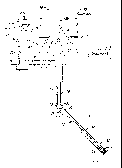
[0012] FIG. 1 shows a schematic diagram of a drilling system 10 with a
drillstring 20
carrying a drilling assembly 90 (also referred to as the bottom hole assembly,
or
ABHA@) conveyed in a "wellbore" or "borehole" 26 for drilling the wellbore.
The
drilling system 10 includes a conventional derrick 11 erected on a floor 12
which
supports a rotary table 14 that is rotated by a prime mover such as an
electric motor
(not shown) at a desired rotational speed. The drillstring 20 includes a
tubing such as
a drill pipe 22 or a coiled-tubing extending downward from the surface into
the
borehole 26. The drillstring 20 is pushed into the wellbore 26 when a drill
pipe 22 is
used as the tubing. For coiled-tubing applications, a tubing injector, such as
an
injector (not shown), however, is used to move the tubing from a source
thereof, such
as a reel (not shown), to the wellbore 26. The drill bit 50 attached to the
end of the
drillstring breaks up the geological formations when it is rotated to drill
the borehole
26. If a drill pipe22 is used, the drillstring 20 is coupled to a drawworks 30
via a
Kelly joint 21, swivel, 28 and line 29 through a pulley 23. During drilling
operations,
the drawworks 30 is operated to control the weight on bit, which is an
important
parameter that affects the rate of penetration. The operation of the drawworks
is well
known in the art and is thus not described in detail herein.
[0013] During drilling operations, a suitable drilling fluid 31 from a mud pit
(source)
32 is circulated under pressure through a channel in the drillstring 20 by a
mud pump
34. The drilling fluid passes from the mud pump 34 into the drillstring 20 via
a
desurger 36, fluid line 28 and Kelly joint 21. The drilling fluid 31 is
discharged at the
borehole bottom 51 through an opening in the drill bit 50. The drilling fluid
31
circulates uphole through the annular space 27 between the drillstring 20 and
the
borehole 26 and returns to the mud pit 32 via a return line 35. The drilling
fluid acts
6
CA 02699330 2010-03-11
WO 2009/029850
PCT/US2008/074871
to lubricate the drill bit 50 and to carry borehole cutting or chips away from
the drill
bit 50. A sensor S1 placed in the line 38 may provide information about the
fluid flow
rate. A surface torque sensor S2 and a sensor S3 associated with the
drillstring 20
respectively provide information about the torque and rotational speed of the
drillstring. Additionally, a sensor (not shown) associated with line 29 is
used to
provide the hook load of the drillstring 20.
[0014] In one embodiment of the disclosure, the drill bit 50 is rotated by
only rotating
the drill pipe 22. In another embodiment of the disclosure, a downhole motor
55
(mud motor) is disposed in the drilling assembly 90 to rotate the drill bit 50
and the
drill pipe 22 is rotated usually to supplement the rotational power, if
required, and to
effect changes in the drilling direction.
[0015] In the embodiment of FIG. 1, the mud motor 55 is coupled to the drill
bit 50
via a drive shaft (not shown) disposed in a bearing assembly 57. The mud motor
rotates the drill bit 50 when the drilling fluid 31 passes through the mud
motor 55
under pressure. The bearing assembly 57 supports the radial and axial forces
of the
drill bit. A stabilizer 58 coupled to the bearing assembly 57 acts as a
centralizer for
the lowermost portion of the mud motor assembly.
[0016] In one embodiment of the disclosure, a drilling sensor module 59 is
placed
near the drill bit 50. The drilling sensor module contains sensors, circuitry
and
processing software and algorithms relating to the dynamic drilling
parameters. Such
parameters may include bit bounce, stick-slip of the drilling assembly,
backward
rotation, torque, shocks, borehole and annulus pressure, acceleration
measurements
and other measurements of the drill bit condition. A suitable telemetry or
communication sub 72 using, for example, two-way telemetry, is also provided
as
illustrated in the drilling assembly 100. The drilling sensor module processes
the
sensor information and transmits it to the surface control unit 40 via the
telemetry
system 72.
7
CA 02699330 2010-03-11
WO 2009/029850
PCT/US2008/074871
[0017] The communication sub 72, a power unit 78 and an MWD tool 79 are all
connected in tandem with the drillstring 20. Flex subs, for example, are used
in
connecting the MWD tool 79 in the drilling assembly 90. Such subs and tools
form
the bottom hole drilling assembly 90 between the drillstring 20 and the drill
bit 50.
The drilling assembly 90 makes various measurements including the pulsed
nuclear
magnetic resonance measurements while the borehole 26 is being drilled. The
communication sub 72 obtains the signals and measurements and transfers the
signals,
using two-way telemetry, for example, to be processed on the surface.
Alternatively,
the signals can be processed using a downhole processor in the drilling
assembly 90.
[0018] The surface control unit or processor 40 also receives signals from
other
downhole sensors and devices and signals from sensors S1-S3 and other sensors
used
in the system 10 and processes such signals according to programmed
instructions
provided to the surface control unit 40. The surface control unit 40 displays
desired
drilling parameters and other information on a display/monitor 42 utilized by
an
operator to control the drilling operations. The surface control unit 40 may
includes a
computer or a microprocessor-based processing system, memory for storing
programs
or models and data, a recorder for recording data, and other peripherals. The
control
unit 40 is may be adapted to activate alarms 44 when certain unsafe or
undesirable
operating conditions occur. The system also includes a downhole processor,
sensor
assembly for making formation evaluation and an orientation sensor. These may
be
located at any suitable position on the bottomhole assembly (BHA).
[0019]Turning now to FIG. 2, a permanent magnet 203 is shown on a drill collar
section 201 of the secondary well. The magnet is transversely magnetized with
the
flux direction indicated by 221. The pre-existing well casing is denoted by
205. The
coordinate axes x, y, and z are as indicated in the figure. The collar section
is provided
with a coil 213. The coil rotates synchronously with the magnet, but the
magnet-coil
combination need not be synchronous with the rotation of the drill collar:
this may be
done by having the magnet-coil combination on a sleeve. The rotating magnet
generates a variable magnetic field at a magnetic object such as the casing
205 of the
8
CA 02699330 2010-03-11
WO 2009/029850
PCT/US2008/074871
pre-existing well. This variable magnetic field induces magnetization in the
casing
that, in turn, generate a variable magnetic flux picked up by the rotating
coil 213.
[0020] The magnetic field generated by the magnet at the target well position
can be
approximated by the point dipole formula:
_
1 3 ( ) 1
MAGNET -=
47r. r 5 r3 ( ),
where Pm is the dipole moment of the magnet, and i is the distance from the
magnet
center to a point on the casing 205. When the magnet 203 rotates in the XY
plane
with angular velocity co, then
/3= pni [cos (cot)e,, + sin (cot) e yi (2),
where ê), and e y are unit vectors in the x- and y- directions respectively.
The rotating
coil sensitivity function (magnetic field produced by the coil driven with a
unit
current) can be written as:
ACOIL
COIL = = MAGNET (3).
Pm
Here S;c0,1 is the sensitivity function of the coil and Acom is the effective
area of the coil.
The rotating magnet generates variable magnetization in the casing. The
magnetization induces a variable magnetic flux in the coil. Based on the
principle of
reciprocity, the corresponding voltage can be expressed as:
V COIL = ¨dt RASING t) =" S COIL(F,t)dv (4),
CASING VOLUME
where .1171 cAsi NG is the magnetization of the casing, and &on, is the coil
sensitivity
function.
[0021] In eqn. (4) the sensitivity S;con., can be considered as a slowly
varying
function over the cross-sectional area of the casing. Therefore, we can
introduce a
9
CA 02699330 2010-03-11
WO 2009/029850
PCT/US2008/074871
magnetization average over the cross-sectional area of the casing as:
05/(As/NG =1
A __________________________ iCiCASING )(elf = MAGNET _XY 4-
fiCASING CROSS _SECTION (5),
+ X eff _z = MAGNET _Z (-1-44a 5t)
where xeff_, and ,refi are the effective magnetic susceptibilities in the
direction
perpendicular and parallel to the casing axis respectively, AcAsING is the
effective area
of the casing, and i;õ represents points along the axis of the casing. Due to
the shape of
the casing we can use the following simlification: X eff xy eff This then
gives,
for the coil voltage, the equation:
V COIL =PO = eff _z = ACASING = Acoll dt silIMACNFT Z , dr,
(6).
P "' LENGTH ¨
This then gives the approximate result
31/o = Xeff_z ' ACASING = ACOIL = Pm = W
Vcoll, == cos(2co = t) (7).
647r 2 = r:
Here ACASING is the cross-sectional area of the casing.
[0022] For practical values xeff z=100, AcAstric = 27c.10-3 m2, o) = 27t 5 51
, Acoll, = 0.2
.200m2,põ, = 1000A- m2, and separation between wells ro =10m, the estimated
voltage
amplitude Võ,= 48 nV. In case the thermal noise in the coil and the
preamplifier noise
are the only sources of noise the signal-to-noise ratio per 1 second
measurement time
can be expected to be around 20. If ro =5m, then Vm=0.75 V.
[0023] It is important to note from eqn. (7) that the voltage induced in the
rotating
coil by the rotating magnetization of the casing has a frequency which is
twice the
rotation frequency of the magnet/coil assembly. This means that the measured
proximity signal is relatively easy to separate from a parasitic signal
induced in the
rotating coil due to the earth's magnetic field. The parasitic signal has a
frequency
equal to the magnet/coil rotation frequency.
CA 02699330 2010-03-11
WO 2009/029850
PCT/US2008/074871
[0024] The main sources of error in the measurement technique is due to the
presence
of some second harmonic in the magnet/coil assembly rotation. In this case the
earth's magnetic field related signal would appear at the frequency ao thus
giving a
spurious signal at the same frequency as the expected proximity signal.
Fortunately,
the presence of ao -component in the rotation speed can be assessed with an
accelerometer and then the data can be used for eliminating the spurious
signal from
the measurement results. The second harmonic signal is easy to calculate from
the
accelerometer output, known value and direction of the earth's magnetic field,
and
measurements of borehole inclination and azimuth. A gyro survey may be needed
to
get the borehole inclination and azimuth.
[0025] FIG. 3 illustrates azimuthal dependence of the voltage on the rotating
coil
213. Using reference voltage
VF CC cos(2co = t), (8)
synchronized with the magnet/coil rotation, the following expression for the
voltage
on the coil 213 can be written
VF = V. = COS[2(CO = t 90 )]. (9)
Here goo is the azimuth of the casing with respect to the secondary well.
Thus the phase of the signal on the coil 213 is sensitive to the azimuthal
position of
the casing 205 with respect to the secondary well 201.
[0026] FIG. 4 is a block diagram illustrating an implementation of the
rotational
magnetometer. The magnetometer comprises a motor 401 rotating the magnet 203
and the coil 213. The signal from the coil 213 transferred to the low noise
preamplifier 409 via an adapter (e. g. sliding rings) 407. Provision is made
to
eliminate parasitic signal ao generated by the Earth's magnetic field in
presence of
rotational disturbances: the signals from rotational accelerometer 411 and the
motor
driver 403 are used to eliminate parasitic signals from the measurement data.
Serving
11
CA 02699330 2010-03-11
WO 2009/029850
PCT/US2008/074871
this purpose are also a controller 405, analog-to-digital converters 413, 417,
419,
digital signal processor 415 and a variable gain amplifier 419.
[0027] Those versed in the art and having benefit of the present disclosure
would
recognize that it is sufficient for the coil 213 to be able to responsive to a
component
of the magnetic flux due to the induced magnetization that is transverse to
the z- axis.
The configuration of the coil 213 shown in FIG. 2 is not the only arrangement
that
would provide a suitable signal, but it is one of the better designs. In
principle, an
inclined planar coil on the BHA with the coil axis inclined to the z- axis
would work.
[00281 FIG. 5 illustrates an example of embodiment of the technique that
utilizes a
[0029] An important feature of the rotational magnetometer described above is
that
12
CA 02699330 2010-03-11
WO 2009/029850
PCT/US2008/074871
makes the induction method with the source and the sensor coil placed in one
well
feasible. Another way to eliminate the direct field signal is to use transient
mode of
inducing magnetization in the target casing ¨ transient magnetometer.
[0030] FIG. 6 depicts an embodiment of the transient magnetometer. The
magnetometer comprises a source of switchable magnetic field 601 having a
switching coil 603 and a magnetic core 605. The magnetic field source 601
generates
magnetic field (the isolines of the field are shown at 607) at a position of
the target
casing 205. The magnetic core 605 may comprises a magnetic material with
residual
magnetization. The residual magnetization is used to provide a strong magnetic
dipole without the need for a DC current driving the switching coil and
causing a
significant energy loss if a strong magnetic field needs to be generated (the
application of the magnetic material with residual magnetization in a source
of a
strong switchable magnetic field is described in US patent application Ser.
No.
11/037,488). Disclosed therein is a magnetic core having residual
magnetization.
Switching the current in the coil results in magnetization reversal in the
magnetic core
and change in magnetic dipole moment. After the magnetization reversal is
complete
the current is removed and the new vector of magnetic dipole maintains
constant
(steady-state phase of the antenna dipole) due to magnetic hysteresis of the
magnetic
material employed for the magnetic core. The magnetometer also comprises a
longitudinal coil 609 to pickup a variable magnetic flux produced by the
casing
magnetization transient occurring in response to switching of the
magnetization in the
magnetic core 605. The magnetometer further comprises a transversal coil 611,
the
signal induced in this coil is sensitive to the azimuthal position of the
casing with
respect to the secondary well 201 when the drill collar rotates.
[0031] FIG. 7 shows time diagrams of the switchable magnetic field and the
transient
responses in the coil 609. The switchable magnetic field 703 is generated by
switching polarity of the residual magnetization in the magnetic core 605. The
switching polarity is accomplished by driving the switching coil 603 with
short pulses
of electric current 701. Decaying signals 705, 707, 709 (transients) in the
coil 609 are
13
CA 02699330 2010-03-11
WO 2009/029850
PCT/US2008/074871
generated in response to a fast switching off or changing polarity of a
"static"
magnetic field. The signals are associated with direct coupling between the
source
and the sensing coil (transient at 705), the signal due to eddy currents in
the
surrounding rock formations and the conductive collar of the drill string (a
conductive
body) placed in the well 201 (transient at 707), and casing proximity signal
due to
variable magnetization of the magnetic casing 205 (transient at 709). It is
important
for the method that the proximity signal 709 is substantially longer than the
undesired
signals 705 and 707. It follows from the fact that a time constant of the
transient
decay is proportional to the effective magnetic permeability of a magnetic
conductor.
It is to be noted that unlike in the first embodiment, the direction of the
magnetic field
does not rotate¨it only switches polarity. As the coil 609 is also
longitudinal, no
sinusoidal variation will occur.
[0032] The following expression for the time constant of building up of the
average
(over the cross-sectional area) magnetization of the casing can be used [see,
for
example, Polivanov, K.M. Electrodinamika veshchestvennykh sred, 1988]
oc 2 . 0 p . (1 0)
Here 5 is the wall thickness of the casing, p is the magnetic permeability,
which is
about 100 for a typical casing material, and o- is the conductivity of the
material of the
casing. The process of building up of the magnetic flux in the coil 609 is
exponential
with the time constant given by eqn.(10). By the time approximately equal to
the
time constant of the casing magnetization process all other transients will
substantially decay. Thus, by measuring the signal in a time window (at 711)
starting
after a time comparable with the time constant of building up of the casing
magnetization (time window 711) one effectively eliminates all undesired
signal. The
expected time constant of the direct coupling is of the order of the duration
of the
pulses 701. In one embodiment, the area within the window is used as a
distance
indicator. Appropriate calibration is carried out. The processes due to the
eddy
current in the conductive surroundings are in the range 1-100 s. The signal
from the
14
CA 02699330 2010-03-11
WO 2009/029850
PCT/US2008/074871
magnetic casing should last approximately 10-30ms. Thus practical acquisition
window may be positioned between lms and 50 ms. Those versed in the art and
having benefit of the present disclosure would recognize that it is sufficient
that the
magnet has a longitudinal component, and the coil is oriented so that is
responsive to
magnetic flux changes in the longitudinal direction.
[0033] FIG. 8 illustrates an embodiment of the disclosure in secondary
recovery
operations. A producing wellbore 820 has been drilled into a reservoir
interval 801
that contains hydrocarbons. For various reasons, such as low formation
pressure or
high viscosity of the hydrocarbons in the reservoir, production under natural
conditions of hydrocarbons may be at uneconomically low rates. In such cases,
a
second wellbore 822 is drilled, typically as a sidebore from the wellbore 820
so as to
be substantially parallel to the main wellbore within the reservoir. The
producing
wellbore is typically cased with casing 830 that has perforations 834. Fluid,
such as
water, CO2 or steam is then injected into the formation through the secondary
wellbore 822 and the injected fluid drives the hydrocarbons in the formation
towards
the producing wellbore 820 where it may be recovered. Such an operation
requires
careful positioning of the secondary borehole 822 in proximity to the
production
wellbore 820. This may be done by monitoring the voltage in the coil. As can
be
seen from eqn. (7), the voltage varies inversely as the fifth power of the
distance.
Thus, the voltage measurements may be used as either relative distance
indicators
based on voltage changes, or, with proper calibration, as absolute distance
indicators.
[0034] The processing of the data may be done by a downhole processor to give
corrected measurements substantially in real time. Implicit in the control and
processing of the data is the use of a computer program on a suitable machine
readable medium that enables the processor to perform the control and
processing.
The machine readable medium may include ROMs, EPROMs, EEPROMs, Flash
Memories and Optical disks.
[0035] While the foregoing disclosure is directed to the specific embodiments
of the
CA 02699330 2012-07-24
disclosure, various modifications will be apparent to those skilled in the
art. It is
intended that the scope of the claims should not be limited by the preferred
embodiments set forth in the examples, but should be given the broadest
interpretation
consistent with the disclosure as a whole.
16