Note : Les descriptions sont présentées dans la langue officielle dans laquelle elles ont été soumises.
CA 02700166 2010-03-18
WO 2009/042117 PCT/US2008/011012
TITLE OF THE INVENTION
SELF-LUBRICATING FASTENERS
CROSS REFERENCE TO RELATED APPLICATION
This application claims priority to provisional application USSN
60/974,977, filed September 25, 2007.
BACKGROUND OF THE INVENTION
The invention relates to interlocking rails or teeth comprised of a
polymer and a slip system additive with a roughening agent and lubricant
dispersed throughout the polymer. The self-lubricating interlocking rails
or teeth are used in self-lubricating fastener devices, and in particular
waterproof fastener devices for garments.
A particular advantage is the elimination of the need to apply a
lubricant to the rail at frequent intervals during its lifetime. Some
currently commercial devices require relubrication after every ten cycles
of the closure. This is inconvenient, time consuming, and can result in
contamination of materials in proximity of the device.
Various sliding clasp fasteners with lubricants have been
disclosed. For example, a traditional coil type zipper (coupling elements)
and a slider adapted to close the coils have been disclosed.
In one embodiment, the coils of the fastener are indented in the
surface and mechanically roughened during extrusion or after. A
lubricant is dissolved in an appropriate solvent and coated onto the coils.
The indented surface is suggested to enhance this coating process.
In another embodiment, a slide fastener is made from a pair of
carrier tapes and coupling elements. The coupling elements are either a
spiral or continuous coil formed from a filament. A separate cord of an
absorbent material soaked in lubricant is positioned adjacent to the
coupling elements to reduce friction upon coupling. However, re-
application of such lubricants is typically required.
A slide fastener has also been disclosed with polymer interlocking
members injection molded directly onto a zipper tape. To aide in the
removal of the polymer interlocking members from the die, an organic
CA 02700166 2010-03-18
WO 2009/042117 PCT/US2008/011012
mold release agent such as siloxane is added into the polymer extrusion.
A decrease in pull force of the zipper with the siloxane present is
disclosed. The interlocking members may be rail protrusions, teeth, or
lock and key mechanisms.
Reclosable household storage bags with sliding fastener closures
have also been disclosed. For instance in one such bag, the writing
surface is created on the household storage bag via a surface
roughening or anti-slip agent. A slip agent is then added to the opposing
surface of bag in selected areas, to overcome the anti-slip agent in the
lo opposing surface.
SUMMARY OF THE INVENTION
An aspect of the present invention relates to an interlocking rail for
self-lubricating fastener devices. The rail comprises a polymer and a
slip system additive with a roughening agent and lubricant dispersed
throughout the polymer.
Another aspect of the present invention relates to interlocking
members for self-lubricating fastener devices. The interlocking
members comprise a polymer and a slip system additive with a
roughening agent and lubricant dispersed throughout the polymer, or
alternatively dispersed throughout a region or portion of the polymer.
Another aspect of the present invention relates to a self-lubricating
fastener device comprising at least two interlocking rails wherein at
least one of the interlocking rails comprises a polymer and a slip
system additive with a roughening agent and lubricant dispersed
throughout the polymer.
Another aspect of the present invention relates to a self-lubricating
fastener device comprising two interlocking rails wherein one of the
interlocking rails comprises a polymer and a roughening agent of a slip
system additive dispersed throughout the polymer and the other
interlocking rail comprises a polymer and a lubricant of the slip system
additive dispersed throughout the polymer.
Another aspect of the present invention relates to a self-lubricating
fastener device comprising a plurality of interlocking members, said
interlocking members comprising a polymer and a slip system additive
with a roughening agent and lubricant dispersed throughout the polymer.
2
CA 02700166 2010-03-18
WO 2009/042117 PCT/US2008/011012
Another aspect of the present invention relates to articles such as
garments comprising one or more of these self-lubricating fastener
devices.
Yet another aspect of the present invention relates to methods for
production of interlocking rails or interlocking members and self-
lubricating fastener devices.
Yet another aspect of the present invention relates to an
interlocking rail fastener device that combines high strength and high
flexibility.
BRIEF DESCRIPTION OF THE DRAWINGS
Figure 1 is a diagram of an exemplary fastener device with self-
lubricating interlocking rails of the present invention.
Figure 2 is a side view of a different exemplary design of an
interlocking rail of the present invention.
Figure 3 is a cross-sectional side view of an interlocking rail
portion with a rotation preventer.
Figure 4 is a graph of strength v. flexibility.
Figure 5 is a depiction of rotation preventers.
Figures 6A and 6B is a comparison of the prior art to the present
invention.
DETAILED DESCRIPTION OF THE INVENTION
The present invention provides interlocking rails and interlocking
members for use in self-lubricating fastener devices.
By "article" as used herein is meant to include garments, footwear,
hardwear, bags, protective garments, enclosures such as chemical and
3 o biological protective shelters, and the like.
By "self-lubricating" as used herein it is meant that separate
application and/or re-application of a lubricant to the fastener device to
reduce friction of the fastener device is not required.
By "waterproof' as used herein it is meant any article capable of
withstanding a hydrostatic pressure of at least 1.0 psi for a period of at
least 1.0 minutes.
3
CA 02700166 2010-03-18
WO 2009/042117 PCT/US2008/011012
By "liquid-proof' as used herein it is meant any article that will not
leak or weep liquid when challenged with a test fluid at a pressure of at
least 0.07 bar for a duration of at least 3 minutes. The test fluid is at a
minimum water, and ideally can be a range of liquid chemicals.
By "rotation preventer" as used herein it is meant any means by
which the interlocking portions of the rails are prevented from rotational
movements relative to each other (upon external force applied relative to
the interlocking surfaces) when the fastener is engaged in a "closed" or
"locked" configuration. The rotation preventer keeps the interlocking
lo interface from rotating without adding excessive stiffness to the fastener.
For example, Figure 1 and 4 depict examples of rotation preventers
including, but not limited to, means for preventing rotation, such as
protrusions, knobs, thickened areas and other modifications relative to
the fastener which prevent rotation.
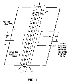
An exemplary fastener device with interlocking rails is depicted in
Figure 1.
As shown in Figure 1, the fastener device I comprises a first rail 2
and a second rail 3 which are fitted to each other via interlocking design
by a metal or plastic slider 7 and a stopper which connects the rails at
one end. As also shown in Figure 1, each rail comprises a tongue
portion 4 and groove portion 5 for interlocking with the other rail and a
flat portion 6 for attachment to an article to be closed with the device.
In one embodiment of the present invention, the self-lubricating
fastener device comprises interlocking rails and one or both rails of the
fastener device comprise a polymer and a slip system additive dispersed
throughout the polymer. The slip system additive comprises a
roughening agent which roughens a surface of the rail and a lubricant
which lubricates a surface of the rail. Exemplary articles closed with
such fastener devices include, but are not limited to, garments, footwear,
3 o bags, gloves, head coverings, protective gear, medical transport
enclosures, tents, and storage bags. In an alternative embodiment, one
of the rails comprises a polymer and a roughening agent of the slip
system additive dispersed throughout the polymer while the other rail
comprises a polymer and a lubricant of the slip system additive
dispersed throughout the polymer.
In yet another embodiment, the self-lubricating fastener device
comprises two sets of interlocking members and one or both sets of
4
CA 02700166 2010-03-18
WO 2009/042117 PCT/US2008/011012
interlocking members of the fastener device comprise a polymer and a
slip system additive dispersed throughout the polymer.
In an alternative embodiment, two sets of interlocking members
are used to create a seal. One set of interlocking members comprises a
polymer and a roughening agent of the slip system additive dispersed
throughout the polymer while the other set of interlocking members
comprises a polymer and a lubricant of the slip system additive
dispersed throughout the polymer.
. Exemplary polymers for use in these rails and interlocking
io members of the present invention include, but are not limited to,
polyurethanes, thermoplastic polymers, silicones, thermoplastic
elastomers or rubbers or the like, polyethylenes, polyesters,
polypropylenes, polyvinyl chlorides, fluoropolymers, and blends thereof.
The slip system additive dispersed throughout the polymer
comprises a roughening agent which roughens a surface of the rail or
interlocking members and a lubricant which lubricates a surface of the
rail or interlocking members. In one embodiment, the slip system
additive comprises at least one roughening agent with at least one
lubricant.
The roughening agent of the slip system additive roughens the
surface of the rail or interlocking members to increase roughness and
reduce the contact points between the surfaces allowing the surfaces to
move past each other with less friction, preferably without changing the
bulk properties of the polymer. Exemplary roughening agents useful in
the slip system additive comprise inorganic materials including, but not
limited to silica, aluminums, silicates, diatomaceous earth, or talc. It is to
be further understood that roughening agents may be chosen from
inorganic or organic materials for the applications taught herein.
The lubricant of the slip system additive reduces friction during
closing and opening of a fastener device comprising the rails or sets of
interlocking members. Lubricants useful in the present invention are
dissolvable in either a polar or non-polar solvent such as alcohol,
preferably ethanol, isopropyl alcohol, hexane, methylene chloride, or
methyl ethyl ketone, or acetone. Such lubricants tend to appear or
reappear at the surface of the polymer and reduce surface friction.
Further, preferred lubricants for use in the present invention do not
interfere with adherence of the fastener device with a hot melt adhesive.
5
CA 02700166 2010-03-18
WO 2009/042117 PCT/US2008/011012
Exemplary lubricants useful in the slip system additive include, but are
not limited to, oleamides, stearamides, ethylene bis-oleamides, ethylene
bis-stearamides, siloxanes, fluorinated polymers and erucamides, stearyl
alcohol, stearic acid, stearates, and metal salts of stearic acid such as
magnesium and calcium, silicones, polytetrafluoroethylene, and the like.
The slip system additive is dispersed in the polymer at a rate of
0.1 to 20 weight percentage, more preferably at a rate of 2 to 5 weight
percentage.
By "dispersed throughout the polymer" as used herein it is meant
that the slip additive agent or a component of the slip additive agent is
diffused evenly or unevenly throughout the polymer so that at least a
portion of the produced rail or interlocking members contain both
polymer and the slip additive agent or a component thereof. Dispersion
of the slip additive agent throughout the polymer eliminates the need to
coat the polymer and/or re-apply lubricant to the fastener device after
use. It is preferred that the slip additive agent is not simply a topical
coating or application as those used for mold release. Conventionally, it
is an unwanted effect to have such slip additive present in or on final
products as they may contribute undesirable qualities.
In one embodiment, the slip system additive is evenly distributed
throughout the polymer and the resulting interlocking rails or interlocking
members. For this embodiment, the interlocking rails or interlocking
members may be produced by blending of the polymer and slip system
additive prior to or during extrusion of the polymer.
Alternatively, the slip system additive may be dispersed
throughout a portion of the polymer and the resulting interlocking rails or
interlocking members. For example, a blend of polymer and slip system
additive can be co-extruded with polymer without slip system additive so
that, for example, the tongue and groove portion of an interlocking rail
comprises polymer and slip system additive while the flat tape portion of
the interlocking rail comprises polymer without slip system additive.
In these embodiments, both the lubricant and the roughening
agent are included in the portion of the polymer containing the slip
system additive.
In an alternative embodiment of the present invention, the self-
lubricating fastener device comprises a first interlocking rail or first set
of
interlocking members comprising a polymer and the roughening agent of
6
CA 02700166 2010-03-18
WO 2009/042117 PCT/US2008/011012
the slip system additive dispersed throughout the polymer of the first rail
or first set of interlocking members and a second interlocking rail or
second set of interlocking members comprising a polymer and a lubricant
of the slip system additive dispersed throughout the polymer of the
second rail or second set of interlocking members.
Also provided in the present invention are methods for production
of self-lubricating fastener devices.
In one embodiment, the method comprises combining or blending
a polymer with a slip system additive. The resulting combination or
blend is then extruded, injected molded, RTV, spin cast, SLA, SLS,
three-dimensional print, CNC or any other suited method for molding the
interlocking pieces into interlocking rails or interlocking members of
polymer with slip system additive dispersed throughout. These
interlocking pieces are then assembled into a self-lubricating fastener
device.
In another embodiment, the method comprises combining or
blending a polymer with a slip system additive. The resulting
combination or blend is then extruded along with a polymer into
interlocking rails or interlocking members, a portion of which comprises
polymer with slip system additive dispersed throughout. These
interlocking pieces are then assembled into a self-lubricating fastener
device.
In another embodiment, the method comprises combining or
blending a polymer with a roughening agent of a slip system additive.
The resulting combination or blend is then extruded into a first
interlocking rail or first set of interlocking members comprising polymer
with roughening agent dispersed throughout. A polymer is also
combined or blended with a lubricant of a slip system additive and the
resulting combination or blend is extruded into a second interlocking rail
or second set of interlocking members comprising polymer with lubricant
dispersed throughout. These first and second rails or first and second
sets of interlocking members are then assembled into a self-lubricating
fastener device.
The self-lubricating fastener devices of the present invention are
liquid-resistant, more preferably liquid-proof. Further, these self-
lubricating fastener devices of the present invention exhibit improved
strength as well as increased strength to mass ratio, making them
7
CA 02700166 2010-03-18
WO 2009/042117 PCT/US2008/011012
stronger and lighter at the same time, as well as increased flexibility, as
compared to waterproof fastener samples prepared using a commercially
available thermoplastic polyurethane (Bayer Texin 990R) and common
profile extrusion processes. In order to provide a device that provides
high strength and flexibility, it is necessary to provide means to prevent
rotation of the interlocking elements relative to themselves during cross-
wise tensile loading. In one embodiment, geometrical features are
altered to prevent such rotation.
Figure 2 shows an aspect of the fastener device 1 which
lo comprises a first rail 2 and a second rail 3 which are able to be fitted to
each other via interlocking design by a slider device used to connect or
separate the interlocking surfaces. As also shown in Figure 2, each rail
comprises a tongue portion 4 and groove portion 5 for interlocking with
the other rail and a flat portion 6 for attachment to an article to be closed
with the device. The rotation preventer 30 is also shown as protrusions
or thickened areas which resist movement of the tongue portions relative
to the groove portions during stress force applications.
Figure 3 shows a fastener device 1 which comprises a first rail 2
and a second rail 3 which are fitted to each other via interlocking design
to connect the rails. The rotation preventer 30 is also shown as
protrusions or thickened areas which resist movement of the tongue
portions relative to the groove portions during stress force applications.
The necessity for this rotation preventer is depicted in Figures 4
and 5. Figure 5 has four images numbered 5A through 5B. Figure 5A
depicts a cross-section of a rail at the beginning of a cross-pull test.
Figure 5B is the same depiction, but with overlaid lines A and B. Line A
represents the general shape of a portion of the interlock. Line B
represents the orientation of another area of the interlock. Figure 5C is a
depiction of a rail cross-section just prior to rail separation. Figure 5D is
the same depiction as Figure 5C, but with lines A and B again added.
Note that line A is considerably straighter in Figure 5D than it is in
Figure 5B. Also note that line B has an orientation in Figure 5D that is
nearly perpendicular to its orientation in Figure 5B. For both lines A and
B, the changes in shape and orientation are caused by a rotation of
certain areas of the interlock. If structural elements can be added that
prevent this rotation without an undue loss of in-plane flexural flexibility,
the cross-pull strength of the device can be increased while retaining
8
CA 02700166 2010-03-18
WO 2009/042117 PCT/US2008/011012
satisfactory flexural flexibility. Alternatively, these elements can be
added, and the entire cross-section can be scaled down, so as to create
a device with similar strength but improved flexural flexibility.
Figure 6A shows a prior art rail profile. Figure 6B shows the
improved rail design of the present invention illustrating that reduction of
tooth rotation is accomplished by elimination of unnecessary undercut
sizing 100 on reduction of the overhang 200 of the undercut on the
tongue portion in conjunction with an increased reinforced area 300.
This allows prevention of head rotation relative to the neck portion of the
lo tongue.
For example, a self-lubricating fastener device of the present
invention comprising interlocked rails is able to withstand up to 50
pounds of force applied in the direction depicted in Figure 1 as measured
per ASTM D2061-07. This is known as cross-pull strength
measurement. Flexibility, as assessed via a three-point bending method,
was also increased. For this assessment, a TA Instruments RSA3
Dynamic Mechanical Analyzer (DMA) with standard 25 mm span three-
point bending fixture was used. Samples were tested as paired rails with
a preload of 1.0 g, a max deflection of 1.0 mm and a rate of 0.25
mm/seconds. The slope of the load-deflection curve between 0.3 and
1.0 mm was used in to calculate flexibility. The flexibility is defined as
the inverse of the product of the elastic modulus (E) and the second
moment of inertia (I), designated (EI)"'. For three-point bending, (EI)-' _
48y/PL3, where y = deflection, P = load, and L = span = 25 mm.
An interlocking rail of the present application comprises a polymer
and a slip system additive dispersed throughout the polymer. The rail
has been found to have favorable strength to mass ratios of greater than
2.99 Nm/g. Further, the mass per unit length of the rail has been found
to be less than 80 grams per meter as exemplified in the examples.
Surface roughness was performed using a Zygo New View 5032
optical profilometer, with a 10X objective. Samples were mounted onto a
glass slide using carbon tape and placed on a leveled stage for
roughness analysis. Three 1.0 mm scans per sample were measured.
All data is recorded in microns. The data is fitted to a straight baseline
and unfiltered. The reported data is for the direction parallel to the
interlocking rail. The average roughness (Ra) reported is the average
distance between the surface and the meanline looking at all of the
9
CA 02700166 2010-03-18
WO 2009/042117 PCT/US2008/011012
points along the profile. It has been found possible to achieve surface
roughness parallel to the rail of greater than 0.3 micrometers Ra.
Thus, the self-lubricating fastener devices of the present invention
are particularly useful in production of water-resistant or waterproof
articles requiring fastener devices such as garments and bags. The self-
lubricating fastener devices of the present invention are useful in joining
gloves and socks to chemical and/or biological protective gear as well as
in liquid-resistant or liquid-proof garments.
The following non-limiting examples are provided to further
lo illustrate the present invention.
Examples
Example 1: Comparative Waterproof Fastener
A waterproof fastener sample (CH1351-37-15) was prepared
using commercially available thermoplastic polyurethane (Bayer Texin
990R) and common profile extrusion processes. The profile of the
resulting rail consisted of a tail section for garment attachment, a
transition section, and a twin-mushroom style interlock section (see
2 o Figure 2). The opposing rail sections were identical. Following
extrusion, the rails were sprayed with a lubricant by 303 Aerospace
Lubricant made by 303 Products Palo Cedro, CA then assembled
together, and tested. The mass per unit length of the sample was 52
grams/meter. The mean cross-pull strength was 89 Newtons (N). The
flexural flexibility was 1421 Newtons/meter (N-1 m"2) . The strength-mass
ratio was 1.70 (Newtons x meters)/gram or (Nm/g). The strength-
flexibility product was 126943 m-2. The average surface roughness (Ra)
in the extruded direction was 0.24 pm.
3 o Example 2: Comparative Waterproof Fastener
A waterproof fastener sample (CH1351-37-16) was prepared
similarly to that of Comparative Example #1, except that the extrusion
speed was adjusted so that the mass per unit length of this sample was
68 grams/meter. The mean cross-pull strength was 100 N. The flexural
flexibility was 1388 N-1 m"2. The strength-mass ratio was 1.46 Nm/g. The
strength-flexibility product was 138337m-2. The average surface
CA 02700166 2010-03-18
WO 2009/042117 PCT/US2008/011012
roughness (Ra) in the extruded direction was 0.28 pm.
Example 3: Waterproof Fastener
A waterproof fastener sample (CH1351-37-1) was prepared from
Estane 58219 resin (available from Lubrizol, Wickliffe, Ohio) blended
with Estane Slip System X-4036 using common profile extrusion
processes as described in Comparative Example 1. Like Comparative
Example 1, the rail profile consisted of a tail section for garment
attachment and a transition section. However, the rail comprised a twin-
wave style interlock section (see Figure 3). No additional lubricant was
applied to the sample following extrusion. The mass per unit length of
the sample was 71 grams/meter. The mean cross-pull strength was 212
N. The flexural flexibility was 1186 N"1 m"2. The strength-mass ratio was
2.99 Nm/g. The strength-flexibility product was 251000 m-2. The
average surface roughness (Ra) in the extruded direction was 0.40 pm.
Example 4: Waterproof Fastener
A waterproof fastener sample.(CH1351-37-2) was prepared
similarly to that in Example 1, except that the extrusion speed was
2 o adjusted so that the mass per unit length of the sample was 47 g/m. The
mean cross-pull strength was 143 N. The flexural flexibility was
1800/N-1 m"2. The strength-mass ratio was 3.03 Nm/g. The strength-
flexibility product was 260000 m-Z. The average surface roughness (Ra)
in the extruded direction was 0.40 pm.
Example 5: Waterproof Fastener
A waterproof fastener sample (CH1351-37-5) was prepared
similarly to that in Example 1, except that the extrusion speed was
adjusted so that the mass per unit length of the sample was 34 g/m. The
mean cross-pull strength was 103 N. The flexural flexibility was 4347 N"
'm-2. The strength-mass ratio was 3.01 Nm/g. The strength-flexibility
product was 446000 m-2. The average surface roughness (Ra) in the
extruded direction was 0.75 pm.
Example 6: Waterproof Fastener
A waterproof fastener sample (CH1351-37-3) was prepared
similarly to that in Example 1, except that the extrusion reduction ratio
11
CA 02700166 2010-03-18
WO 2009/042117 PCT/US2008/011012
was adjusted to give a mass per unit length of the sample of 18 g/m.
The mean cross-pull strength was 77 N. The flexural flexibility was 8245
N"'m"Z. The strength-mass ratio was 4.21 Nm/g. The strength-flexibility
product was 638000 m-Z. The average surface roughness (Ra) in the
extruded direction was 0.59 pm.
Example 7: Waterproof Fastener
A sample ZIPLOC "Big Bags" fastener was evaluated for
strength and flexibility. The samples were reassembled so as to be
lo suitable for cross-pull testing. The mean cross-pull strength was 87 N.
The flexural flexibility was 3120 N-1 m-2. The strength-flexibility product
was 271000 m-2. The sample had a glossy appearance, indicating a very
low surface roughness.
Example 8: Waterproof Fastener
A sample YKK rail fastener (Part No. 5PVH) was evaluated for
strength and flexibility. The samples were reassembled so as to be
suitable for cross-pull testing. The mean cross-pull strength was 252 N.
The flexural flexibility was 515 N-1 m-2. The strength-flexibility product
was 129780 m-2. The sample had a glossy appearance, indicating a very
low surface roughness.
The relative strength and flexibility of these Examples 1-8 are
depicted in Figure 4. It can be seen that the invention provides an
improvement in combined strength and flexibility represented by the area
to the right of the solid line. It is to be noted that gross calculations
reported in Examples 1-8 were based upon measured values prior to
rounding to the reported nearest whole number.
Example 9: Test Method
Coefficient of Friction Measurement:
Coefficient of friction measurements (COF) were made using test
method ASTM D1894-06 with a sled speed of 90 inches per minute and
a sled load of 600 gram. The sled base measured 2.5 inches by 2.5
inches. The coefficient of friction was measured ten times per test
specimen and the averages reported in the result table.
12
CA 02700166 2010-03-18
WO 2009/042117 PCT/US2008/011012
Coefficient of Friction Measurements after Abrasion:
Coefficient of friction after abrasion is an important indicator of the
longevity of the effect of added lubricants to a polymer extrusion. Thus,
the flat samples prepared for the coefficient of friction measurements
were also subjected to Martindale Abrasion Testing using a modified
ASTM D4966-98 test method. The modification involved using "0"
Emery Cloth as the abraident and doing 100 cycles (1600 movements)
with a 12kPaA load. After each test specimen was abraded according to
this protocol, the coefficient of friction was again measured using the
lo COF test method. The after abrasion test results are also shown in the
results table.
Example 10: Lubricant Effect
The effect of lubricant on the coefficient to friction (COF) of flat
test specimens the polyurethane material used to make up the rails was
determined experimentally. Flat sheet extrusions of a mixture of Estane
58219 and Estane X4036 polyurethane were prepared using standard
extrusion conditions as recommended by the resin manufacturer. This
master-batch composition was the basis for all subsequent experiments
with various lubricant types and levels added. These samples also
served as the non-lubricated baseline.
To determine the effect of both (1) an erucamide blend lubricant
(ECM Plastics, Inc., Worcester, Massachusetts, part No. CPU310), and
(2) with PTFE micropowder, additional batches of Estane 58219/ Estane
X4036 were compounded but this time with the lubricant included.
These compounded, lubricant-containing batches were then extruded
into flat sheets using similar conditions as those used for the non-
lubricated control samples.
Different concentrations of the erucamide blend lubricant and of
the PTFE micropowder were evaluated. The initial test specimens were
prepared using 0%, 3%, and 6% by weight of erucamide blend lubricant
in the base polyurethane polymer. After these data were determined,
new set of polyurethane extrusions were prepared with the same levels
of lubricant but with the addition of 0%, 3%, and 6% PTFE micropowder
(available from Shamrock as T-815 PTFE micropowder) added into the
compounded mix used to produce the polymer extrusion.
13
CA 02700166 2010-03-18
WO 2009/042117 PCT/US2008/011012
Table 1- Coefficient of Friction Results
PTFE PTFE PTFE PTFE PTFE PTFE
Percentage Percentage Percentage Percenta e Percentage Percenta e
0% weight 0% weight 3% weight 3% wei ht 6% weight 6% wei ht
No 100 No 100 No 100
Abrasion Abrasion Abrasion Abrasion Abrasion Abrasion
Cycles Cycles Cycles
Sample A: >5 lb -- 2.171b 2.05 lb 2.53 lb 2.10 lb
0% weight
CPU310
lubricant
Sample B: 1.81 lb 2.6 lb 2.05 lb 2.47 lb 2.45 lb 2.27 lb
3% weight
CPU310
lubricant
Sample C: 1.36 lb 2.11 lb 2.46 lb 2.32 lb 2.66 lb 1.23 lb
6% weight
CPU310
lubricant
Based on Table 1 above, several lubrication conclusions can be
reached. The addition of the lubricant lowers the COF of the initial
samples with no abrasion. However after abrasion, the COF increases.
This increase of COF after abrasion suggests that the lubricant
effectiveness is decreasing. In contrast, when the PTFE micropowder is
lo additionally added to a lubricated sample, the COF after abrasion does
not increase.
Example 11:
The effect on rail zipper pull force was determined based on
ls Sample B in Table 1. The zipper pull force was measured using a
modified ASTM D1876, where the pull rate was 12 inches per second
over a range of 14 inches. The average of the pull force readings was
reported. Rails with the same composition as Sample B with no PTFE
micropowder were compared to rails with the same composition as
20 Sample B with 3% PTFE micropowder added. In order to normalize
these data, the results reported are the ratio of pull force for each pull
divided by the initial pull force. These results are shown in Table 2
below.
25 These results show that without the PTFE micropowder, the pull
force increases with the number of test cycle pulls until it plateaus off at
14
CA 02700166 2010-03-18
WO 2009/042117 PCT/US2008/011012
about 200 cycles until the end of the test at 300 cycles. The plateau
value shows the pull force in the absence of the PTFE micropowder has
more than doubled by about 200 cycles. In contrast, the pull force with
the PTFE micropowder present increases slightly up to about 50 cycles
and then levels off to about 200 cycles, after which, the pull force begins
to decrease. By the end of this 300 cycle test, the final pull force with the
PTFE micropowder is essentially the same at the initial pull force.
Table 2
Sliding Pull Force (zipping)
Room Temperature
2.2
2
1.8 - -- - -- - ~ _
a
W
ML 1.6
0
w
0
1.4
1.2
0 50 100 150 200 250 300 350
test cycles
--0- (lube only) --m-- (PTFE + Lube)