Sélection de la langue

Search

Sommaire du brevet 2701328 

Énoncé de désistement de responsabilité concernant l'information provenant de tiers

Une partie des informations de ce site Web a été fournie par des sources externes. Le gouvernement du Canada n'assume aucune responsabilité concernant la précision, l'actualité ou la fiabilité des informations fournies par les sources externes. Les utilisateurs qui désirent employer cette information devraient consulter directement la source des informations. Le contenu fourni par les sources externes n'est pas assujetti aux exigences sur les langues officielles, la protection des renseignements personnels et l'accessibilité.

Disponibilité de l'Abrégé et des Revendications

L'apparition de différences dans le texte et l'image des Revendications et de l'Abrégé dépend du moment auquel le document est publié. Les textes des Revendications et de l'Abrégé sont affichés :

  • lorsque la demande peut être examinée par le public;
  • lorsque le brevet est émis (délivrance).
(12) Demande de brevet: (11) CA 2701328
(54) Titre français: DISQUE DE FREIN
(54) Titre anglais: BRAKE DISC
Statut: Réputée abandonnée et au-delà du délai pour le rétablissement - en attente de la réponse à l’avis de communication rejetée
Données bibliographiques
(51) Classification internationale des brevets (CIB):
  • F16D 65/12 (2006.01)
(72) Inventeurs :
  • GASPERS, HEINZ-JUERGEN (Allemagne)
  • HOFFMANN, HELMUT (Allemagne)
(73) Titulaires :
  • FAIVELEY TRANSPORT WITTEN GMBH
(71) Demandeurs :
  • FAIVELEY TRANSPORT WITTEN GMBH (Allemagne)
(74) Agent: MBM INTELLECTUAL PROPERTY AGENCY
(74) Co-agent:
(45) Délivré:
(86) Date de dépôt PCT: 2008-07-15
(87) Mise à la disponibilité du public: 2009-04-09
Licence disponible: S.O.
Cédé au domaine public: S.O.
(25) Langue des documents déposés: Anglais

Traité de coopération en matière de brevets (PCT): Oui
(86) Numéro de la demande PCT: PCT/EP2008/005762
(87) Numéro de publication internationale PCT: EP2008005762
(85) Entrée nationale: 2010-03-29

(30) Données de priorité de la demande:
Numéro de la demande Pays / territoire Date
20 2007 013 658.7 (Allemagne) 2007-09-28

Abrégés

Abrégé français

L'invention concerne un disque de frein (100), comprenant une bague de friction plane (10) sur laquelle est formé un ergot de disque de frein (17) pourvu d'un perçage d'ergot (20). L'invention vise à perfectionner le disque de frein (100) de manière à obtenir une sécurité suffisante relativement aux valeurs de matériau admissibles pour des disques de frein (100) destinés à des applications hautement énergétiques, et à réduire les tensions du matériau qui sont produites dans la région de l'ergot de disque de frein (17) du disque de frein (100) par des différences de température à l'intérieur du disque de frein (100) suite à des apports élevés d'énergie de freinage. A cet effet, l'ergot de disque de frein (17) présente deux parties de bras (18, 19), qui s'étendent à distance entre elles depuis la bague de friction plane (10) en direction du perçage d'ergot (20) et qui se rejoignent avant le perçage d'ergot (20).


Abrégé anglais


The invention relates to a brake disc (100) having a face-end friction ring
portion (10) on which a brake disc cam (17) provided with a cam bore (20)
is moulded. In order to further develop the brake disc (100) in such a
manner that adequate safeties with respect to the permissible material
values on brake discs (100) for high-energy application cases are provided
and material stresses in the region of the brake disc cam (17) of the brake
disc (100), which are caused through temperature differentials within the
brake disc (100) as a consequence of high braking energy inputs, are
reduced, the invention proposes that the brake disc cam (17) comprises
two arm parts (18, 19) which extend spaced from each other from the
face-end friction ring portion (10) in the direction of the cam bore (20) and
converge in front of the cam bore (20).

Revendications

Note : Les revendications sont présentées dans la langue officielle dans laquelle elles ont été soumises.


8
Claims
1. A brake disc (100) having a face-end friction ring portion (10) on
which a brake disc cam (17) provided with a cam bore (20) is
moulded, characterised in that the brake disc cam (17) comprises
two arm parts (18, 19) which extend spaced from each other from the
face-end friction ring portion (10) in the direction of the cam bore (20)
and converge in front of the cam bore (20).
2. The brake disc according to Claim 1, characterised in that the arm
parts (18, 19) extend in the direction of an inner edge (11) of the
face-end friction ring portion (10).
3. The brake disc according to Claim 2, characterised in that the cam
bore (20) is arranged offset from the inner edge (11).
4. The brake disc according to any one of the Claims 1 to 3,
characterised in that the arm parts (18, 19) each comprise a web (21,
22) which are moulded on the face-end friction ring portion (10) and
which are followed by arms (23, 24) which are substantially arranged
parallel and spaced from the face-end friction ring portion (10).
5. The brake disc according to any one of the preceding claims,
characterised in that the radius of the webs (21, 22) increases
towards the surface of the face-end friction ring portion (10).
6. The brake disc according to any one of the preceding claims,
characterised in that the brake disc cam (17) tapers towards the cam
bore (20).

9
7. The brake disc according to Clam 4 to 6, characterised in that the
brake disc cam (17) is moulded in a roundish manner on a side (27)
facing away from the webs.
8. The brake disc according to any one of the Claims 4 to 7,
characterised in that the webs (21, 22) are configured inclined in
axial direction and towards the inner edge (11).
9. The brake disc according to any one of the Claims 4 to 8,
characterised in that the arms (23, 24) are laterally extended away
from each other in the direction of the outer edge (12) of the face-end
friction ring portion (10).
10. The brake disc according to any one of the Claims 4 to 9,
characterised in that the arms (23, 24) on their narrow sides (25, 26)
which converge in front of the cam bore (20) are roundish in shape.
11. The brake disc according to any one of the Claims 4 to 6,
characterised in that the brake disc cam (17) on the side (27) facing
away from the web is configured oval in shape.
12. The brake disc according to any one of the preceding claims,
characterised in that the brake disc cam (17) is arranged between
cooling ribs (16).
13. The brake disc according to any one of the preceding claims,
characterised in that between brake disc cam (17) and outer edge
(12) of the face-end friction ring portion (10) cooling ribs (14, 15) are
arranged.

10
14. The brake disc according to any one of the preceding claims,
characterised in that the brake disc cam (17) is arranged on a brake
disc belt (13) of the friction ring portion (10).

Description

Note : Les descriptions sont présentées dans la langue officielle dans laquelle elles ont été soumises.

CA 02701328 2010-03-29
Brake disc
Technical Area
The invention relates to a brake disc having a face-end friction ring portion
out of which a brake disc cam with a cam bore is moulded.
Prior art
Brake discs of the type mentioned at the outset are known and familiar to
the person skilled in the art, wherein the brake discs can be embodied in
one part or two parts.
Two-part brake discs comprise a first and second disc half each of which
is configured in the shape of a half circle or half ring and are brought
together in a partition plane in order to form a brake disc ready for
operation. Thus, because of its split embodiment, the brake disc can be
arranged on shafts which do not permit axial assembly of the brake discs
because of the geometrical configuration of the shaft.
The inner ventilation of the brake discs is made possible in that the brake
discs comprise a first friction ring portion as well as a second friction ring
portion and the friction ring portions are arranged plane-parallel to each
other with a certain spacing. Between the two friction ring portions a
multiplicity of cooling ribs is arranged between which in turn ventilation
channels run. Through the brake disc rotation cooling air is directed
through the ventilation channels in order to prevent excessive heating of
the entire brake disc as a result of conversion of the braking power.
In order to additionally guarantee the operational safety even with high
operating loads through shock loading and through thermal loads the
German utility model No. 20 2007 009 345.4 additionally provides that
brake disc cams are arranged between the cooling ribs. These cams can
be present in the shape of tie-up cams which are arranged in the

CA 02701328 2010-03-29
2
immediate vicinity of the brake belt and for example establish the
connection between the brake disc and a disc hub. Here, the cams
protrude radially from a friction ring portion in the direction of the centre
point of the brake disc.
The shape of the cams in this context has to interact with the arrangement
and shape of the cooling ribs in such a manner that the operational safety
is also guaranteed in the case of high operating loads through shock
loading as well as through thermal loads.
In particular, stop braking from a high speed can cause high inputs of
braking energy. These braking energy inputs in turn can generate
temperature differentials within the brake disc which result in material
stresses in the region of the tie-up cams of the brake disc.
Presentation of the invention, object, solution, advantages
Appreciating the shown prior art with brake discs of the type mentioned at
the outset, the object of the present invention is therefore based on further
developing a brake disc of the type mentioned at the outset in such a
manner that adequate safeties with respect to the permissible material
values on brake discs for high-energy application cases are provided. In
addition, material stresses in the region of the brake cams of the brake
disc, which are caused through temperature differentials within the brake
disc as a result of high braking energy inputs are to be reduced.
This object is solved with the features of Claim 1. Advantageous
embodiments of the invention are obtained from the subclaims.
According to the invention the brake disc cam comprises two arm parts
which extend spaced from each other from the face-end friction ring
portion in the direction of the cam bore and converge in front of the cam
bore.

CA 02701328 2010-03-29
3
Each of the arm parts comprises a web which is moulded out of the face-
end friction ring portion and which are followed by arms which are
substantially parallel and spaced from the face-end friction ring portion. In
this manner it is ensured that the brake disc cam is tied to the brake belt,
which runs on the inner edge of the friction ring portion via two completely
separated webs. The basic idea of the invention is the splitting of the
brake disc cam into two separate arm parts except in the region of the
cam bore.
The advantage of the invention is that through a configuration of the brake
disc cam of this type a movement possibility of the arm parts of the cam
upon thermal expansion of the brake disc is provided, thus bringing about
a reduction of the stress increase in the arm parts as well as in the foot
region, that is in the webs of the arm part. The brake disc according to the
invention is more preferably suitable with high shock and thermal
operating loads.
Preferentially the arm parts extend in the direction of an inner edge of the
face-end friction ring portion. The cam bore in this case is arranged offset
from the inner edge.
An advantageous configuration of the invention provides that the radius of
the webs increases towards the surface of the face-end friction ring
portion.
Through such an enlargement of the radii, high compressive-tensile
stresses upon screening of the brake disc are avoided. Another
contribution in this regard is that the webs of the brake disc cam are
shaped in an inclined manner in axial direction and towards the inner edge
of the face-end friction ring portions.

CA 02701328 2010-03-29
4
Preferentially the brake disc cam is formed in a roundish or oval shape on
the side facing away from the web.
Another contribution to further reduction of the material stresses is that the
arms laterally extend away from each other in the direction of the outer
edge of the face-end friction ring portion and the arms on their narrow
sides which converge in front of the cam bore are roundish in shape.
In the context of the invention the brake disc cam follows a brake belt of
the friction ring portion and is thus located in the immediate vicinity of the
brake belt which runs along the inner edge of the friction ring portion.
Further advantageous configurations of the invention provide that the
brake disc cam is arranged between cooling ribs of the friction ring portion.
In addition, the invention provides that cooling ribs are arranged between
the brake disc cams and the outer edge of the face-end friction ring
portion.
Brief description of the drawings
The invention is explained in more detail in the following by means of
Figure 1.
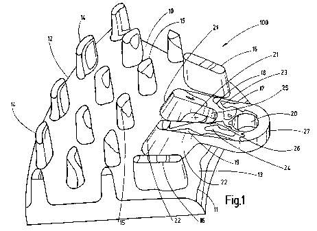
Figurel shows a top view of a detail of a friction ring portion in a schematic
representation, wherein the view shows the arrangement of the cooling
ribs and of the brake disc cam as well as its configuration.
Figurel merely is an exemplary technical embodiment of the present
invention.
Best way to carry out the invention
The brake disc shown in Figure 1 is given the reference number 100.

CA 02701328 2010-03-29
Basically it consists of two face-end friction ring portions, wherein in
Figure
1 merely one friction ring portion 10 is shown. The friction ring portions
form the friction surfaces of the brake disc 100. The friction ring portion 10
is limited by an inner edge 11 and an outer edge 12. In the region of the
inner edge 11 is located the input radius or the brake disc belt 13. A
multiplicity of cooling ribs 14, 15, 16, which cool the brake disc 10 during
the braking operation through resultant convection between the cooling
ribs, extends on the friction ring portion 10. In addition to this, the
cooling
ribs 14, 15, 16 contribute to the mechanical connection between the
friction ring portion 10 and a second friction ring portion of the brake disc
100 which is not shown here.
The brake disc cam 17 is arranged between the cooling ribs 16. In
addition, cooling ribs 14, 15 are located between the brake disc cam 17
and the outer edge 12 of the face-end friction ring portion 10. The brake
disc cam 17 serves to tie the brake disc 100 for example to a hub. In
order to additionally reduce material stresses, the brake disc cam 17
comprises two arm parts 18, 19 which extend spaced from each other
from the face-end friction ring portion 10 in the direction of the cam bore
20 and converge in front of the cam bore 20. Here, the cam bore 20 is
arranged offset from the inner edge 11.
The arm parts 18, 19 each comprise a web 21, 22 which are moulded on
the face-end friction ring portion 100 and which are followed by arms 23,
24 which are substantially arranged parallel and spaced from the face-end
friction ring portion 10. The radius of the webs 21, 22 increases towards
the surface of the face-end friction ring portion 10. In the context of the
invention it is also possible that the brake disc cam 17 tapers towards the
cam bore 20.
In the embodiment shown here the arms 23, 24 are extended laterally
away from each other in the direction of the outer edge 12 of the face-end

CA 02701328 2010-03-29
6
friction ring portion 10. In addition, the arms 23, 24 are shaped in a
roundish manner on their narrow sides 25, 26 which converge in front of
the cam bore 20, whereas the brake disc cam 17 is moulded in a roundish
manner on the side 27 facing away from the web. If applicable, the brake
disc cam 17 on the side 27 facing away from the web can also be formed
oval in shape. For the purpose of avoiding high compressive-tensile
stresses upon screening of the brake disc the webs 21, 22 are configured
inclined in axial direction and towards the inner edge 11.
In its embodiment the present invention is not limited to the preferred
exemplary embodiment stated above. A number of versions is rather
conceivable which make use of the solution shown even with
embodiments of a fundamentally different type. Thus, the webs 21, 22 for
example can have different radii. The cooling ribs 14, 15, 16 obviously
can also have different configurations. In addition, the webs 21, 22 can be
additionally provided with different transition radii. The webs 21, 22 can
also have different shapes.

CA 02701328 2010-03-29
7
List of reference numbers
100 Brake disc
Friction ring portion
11 Inner edge
12 Outer edge
13 Brake disc belt
14 Cooling rib
Cooling rib
16 Cooling rib
17 Brake disc cam
18 Arm part
19 Arm part
Cam bore
21 Web
22 Web
23 Arm
24 Arm
Narrow sides
26 Narrow sides
27 Side facing away from the web

Dessin représentatif
Une figure unique qui représente un dessin illustrant l'invention.
États administratifs

2024-08-01 : Dans le cadre de la transition vers les Brevets de nouvelle génération (BNG), la base de données sur les brevets canadiens (BDBC) contient désormais un Historique d'événement plus détaillé, qui reproduit le Journal des événements de notre nouvelle solution interne.

Veuillez noter que les événements débutant par « Inactive : » se réfèrent à des événements qui ne sont plus utilisés dans notre nouvelle solution interne.

Pour une meilleure compréhension de l'état de la demande ou brevet qui figure sur cette page, la rubrique Mise en garde , et les descriptions de Brevet , Historique d'événement , Taxes périodiques et Historique des paiements devraient être consultées.

Historique d'événement

Description Date
Demande non rétablie avant l'échéance 2011-07-15
Le délai pour l'annulation est expiré 2011-07-15
Inactive : Demande sous art.37 Règles - PCT 2011-06-27
Réputée abandonnée - omission de répondre à un avis sur les taxes pour le maintien en état 2010-07-15
Inactive : Page couverture publiée 2010-06-03
Inactive : Lettre de courtoisie - PCT 2010-05-26
Inactive : Notice - Entrée phase nat. - Pas de RE 2010-05-26
Inactive : CIB attribuée 2010-05-25
Inactive : CIB en 1re position 2010-05-25
Demande reçue - PCT 2010-05-25
Exigences pour l'entrée dans la phase nationale - jugée conforme 2010-03-29
Demande publiée (accessible au public) 2009-04-09

Historique d'abandonnement

Date d'abandonnement Raison Date de rétablissement
2010-07-15

Historique des taxes

Type de taxes Anniversaire Échéance Date payée
Taxe nationale de base - générale 2010-03-29
Titulaires au dossier

Les titulaires actuels et antérieures au dossier sont affichés en ordre alphabétique.

Titulaires actuels au dossier
FAIVELEY TRANSPORT WITTEN GMBH
Titulaires antérieures au dossier
HEINZ-JUERGEN GASPERS
HELMUT HOFFMANN
Les propriétaires antérieurs qui ne figurent pas dans la liste des « Propriétaires au dossier » apparaîtront dans d'autres documents au dossier.
Documents

Pour visionner les fichiers sélectionnés, entrer le code reCAPTCHA :


Pour visualiser une image, cliquer sur un lien dans la colonne description du document. Pour télécharger l'image (les images), cliquer l'une ou plusieurs cases à cocher dans la première colonne et ensuite cliquer sur le bouton "Télécharger sélection en format PDF (archive Zip)" ou le bouton "Télécharger sélection (en un fichier PDF fusionné)".

Liste des documents de brevet publiés et non publiés sur la BDBC .

Si vous avez des difficultés à accéder au contenu, veuillez communiquer avec le Centre de services à la clientèle au 1-866-997-1936, ou envoyer un courriel au Centre de service à la clientèle de l'OPIC.


Description du
Document 
Date
(aaaa-mm-jj) 
Nombre de pages   Taille de l'image (Ko) 
Description 2010-03-28 7 221
Dessins 2010-03-28 1 26
Revendications 2010-03-28 3 64
Abrégé 2010-03-28 1 20
Dessin représentatif 2010-06-02 1 17
Rappel de taxe de maintien due 2010-05-24 1 116
Avis d'entree dans la phase nationale 2010-05-25 1 210
Courtoisie - Lettre d'abandon (taxe de maintien en état) 2010-09-08 1 174
PCT 2010-03-28 4 153
Correspondance 2010-05-25 1 18
Correspondance 2011-06-23 1 21