Sélection de la langue

Search

Sommaire du brevet 2701548 

Énoncé de désistement de responsabilité concernant l'information provenant de tiers

Une partie des informations de ce site Web a été fournie par des sources externes. Le gouvernement du Canada n'assume aucune responsabilité concernant la précision, l'actualité ou la fiabilité des informations fournies par les sources externes. Les utilisateurs qui désirent employer cette information devraient consulter directement la source des informations. Le contenu fourni par les sources externes n'est pas assujetti aux exigences sur les langues officielles, la protection des renseignements personnels et l'accessibilité.

Disponibilité de l'Abrégé et des Revendications

L'apparition de différences dans le texte et l'image des Revendications et de l'Abrégé dépend du moment auquel le document est publié. Les textes des Revendications et de l'Abrégé sont affichés :

  • lorsque la demande peut être examinée par le public;
  • lorsque le brevet est émis (délivrance).
(12) Brevet: (11) CA 2701548
(54) Titre français: SYSTEME POUR LE MONTAGE D'UN MOTEUR SUR LA CELLULE D'UN AERONEF
(54) Titre anglais: ARRANGEMENT FOR MOUNTING AN ENGINE ON THE AIRFRAME OF AN AIRCRAFT
Statut: Périmé et au-delà du délai pour l’annulation
Données bibliographiques
(51) Classification internationale des brevets (CIB):
  • B64D 27/14 (2006.01)
  • B64D 27/20 (2006.01)
(72) Inventeurs :
  • LLAMAS SANDIN, RAUL CARLOS (Espagne)
(73) Titulaires :
  • AIRBUS OPERATIONS S.L.
(71) Demandeurs :
  • AIRBUS OPERATIONS S.L. (Espagne)
(74) Agent: SMART & BIGGAR LP
(74) Co-agent:
(45) Délivré: 2016-05-24
(86) Date de dépôt PCT: 2008-10-03
(87) Mise à la disponibilité du public: 2009-04-09
Requête d'examen: 2013-09-24
Licence disponible: S.O.
Cédé au domaine public: S.O.
(25) Langue des documents déposés: Anglais

Traité de coopération en matière de brevets (PCT): Oui
(86) Numéro de la demande PCT: PCT/EP2008/063274
(87) Numéro de publication internationale PCT: EP2008063274
(85) Entrée nationale: 2010-04-01

(30) Données de priorité de la demande:
Numéro de la demande Pays / territoire Date
P200702585 (Espagne) 2007-10-03

Abrégés

Abrégé français

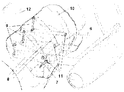
L'invention concerne un système pour le montage d'un système propulsif sur une cellule (12) d'un aéronef au moyen d'un pylône externe (4) qui relie le moteur (1) à la cellule (12). Ledit pylône (4) comprend une pluralité de longerons (8) qui entrent dans la cellule (12) et des moyens (7, 9, 11) qui permettent de fixer lesdits longerons (8) à la structure interne (10) de la cellule. Lesdits moyens (7, 9, 11) sont des amortisseurs, des absorbeurs de chocs ou des actionneurs actifs qui présentent des caractéristiques sélectionnées de sorte que lesdits moyens (7, 9, 11) sont particulièrement appropriés pour la réduction efficace de charges dynamiques internes et de liaison issues principalement mais pas uniquement d'événements d'atterrissages brutaux et de manoeuvres en vol d'aéronefs, et pour amortir les vibrations continues de l'ensemble système propulsif-cellule (12), ledit système permettant de séparer facilement ledit pylône (4) du reste de ladite cellule (12), d'utiliser ledit pylône (4) sur différents aéronefs de manière interchangeable; ledit système étant également tolérant aux dommages ou à une défaillance complète d'au moins un desdits longerons (8).


Abrégé anglais


Arrangement for mounting a propulsive system on an aircraft airframe (12) by
means of an external strut (4) which
connects the engine (1) with the airframe (12), said strut (4) comprising a
plurality of spars (8) intruding into the airframe (12) and
means (7, 9, 11) for attaching said spars (8) to the internal airframe
structure (10), the cited means (7, 9, 11) being dampers, shock
absorbers or active actuators with characteristics chosen so that the said
means (7, 9, 11) are particularly suited for the efficient
reduction of attachment and internal dynamic loads arising mainly but not only
from hard landing events and aircraft flight
manoeuvres, and for damping sustained vibrations of the propulsive system-
airframe (12) assembly, the said arrangement allowing the
easy removal of the strut (4) from the rest of the said airframe (12) and the
interchangeability of the said strut (4) between different
aircrafts, being also the cited arrangement tolerant to damage or complete
failure of at least one of the said spars (8).

Revendications

Note : Les revendications sont présentées dans la langue officielle dans laquelle elles ont été soumises.


9
CLAIMS:
1. A structural configuration for the assembly of the supporting structure
(4) of an
aircraft engine (1) on the fuselage (12) of an aircraft, wherein the
supporting structure (4) of
the engine (1) comprises a closed structure part (6) outside the fuselage (12)
and at least
two spars (8) penetrating the fuselage (12) and connected to the internal
structure (10) of
said fuselage (12) through first and second connecting members (9, 11), said
first members
(9) connecting the end of the spars (8) to the internal structure (10) of the
fuselage (12) and
said second members (11) connecting the mentioned spars (8) to the internal
structure (10)
at the points of said spars (8) closest to the engine (1) thereby forming a
lever arm such
that the inner dynamic loads and the loads from the coupling of the supporting
structure (4)
to the engine (1), generated in cases of sudden landings and in-flight
aircraft maneuvers,
are efficiently reduced, and the continuous vibrations in the engine assembly
(1) and
aircraft are further dampened.
2. A structural configuration for the assembly of the supporting structure
(4) of an
aircraft engine (1) on the fuselage (12) of an aircraft according to claim 1,
wherein the spars
(8) are straight and penetrate the fuselage (12) perpendicular to its outer
surface (10).
3. A structural configuration for the assembly of the supporting structure
(4) of an
aircraft engine (1) on the fuselage (12) of an aircraft according to claim 1,
wherein the first
and the second connecting members (9, 11) are arranged on the longitudinal
axis, said
spars (8), being spaced such that they form an effective support with said
large lever arm to
react due to the mechanical moments produced by gravitational and inertial
forces acting
on the engine (1).
4. A structural configuration for the assembly of the supporting structure
(4) of an
aircraft engine (1) on the fuselage (12) of an aircraft according to claim 3,
wherein the first
and the second connecting members (9, 11) transmit forces perpendicular to the
longitudinal axis of the spars (8), at least one of the first and the second
connecting
members (9, 11) further transmitting forces focused along the longitudinal
axis of said spars
(8).

10
5. A structural configuration for the assembly of the supporting structure
(4) of an
aircraft engine (1) on the fuselage (12) of an aircraft according to claim 1,
wherein the spars
(8) are three in number so as to obtain a redundant and fail-safe structural
configuration.
6. A structural configuration for the assembly of the supporting structure
(4) of an
aircraft engine (1) on the fuselage (12) of an aircraft according to claim 1,
further
comprising at least one additional connecting member (7) connecting the closed
supporting
structure (6) of the engine (1) to the fuselage (12) such that forces are
transmitted in the
longitudinal direction of the aircraft.
7. A structural configuration for the assembly of the supporting structure
(4) of an
aircraft engine (1) on the fuselage (12) of an aircraft according to claim 6,
wherein the first
and the second connecting members and the at least one additional connecting
member
(7, 9, 11) are adjusted such that in normal conditions only a sufficient
number of the
connecting members transmit forces such that the connection of the closed
supporting
structure (6) of the engine (1) to the fuselage (12) is statically determined,
the rest of the
connecting members transmitting forces only in the event of structural failure
or breakage
of other connecting members.
8. A structural configuration for the assembly of the supporting structure
(4) of an
aircraft engine (1) on the fuselage (12) of an aircraft according to claim 6,
wherein several
of the first and the second connecting members and the at least one additional
connecting
member (7, 9, 11) redundantly transmit forces in normal conditions, which
requires that the
geometry of the connecting members (7, 9, 11) connecting the spars (8) to the
internal
structure (10) of the fuselage (12) can be adjusted.
9. A structural configuration for the assembly of the supporting structure
(4) of an
aircraft engine (1) on the fuselage (12) of an aircraft according to claim 6,
wherein the first
and the second connecting members and the at least one additional connecting
member
(7, 9 and 11) are formed by elastomers, wire mesh, viscoelastic type elements,
or
electrohydraulic elements that allow transmitting the forces required between
the spars (8)
and the internal structure (10) of the fuselage (12), these members (7, 9, 11)
having the
desired rigidity and dampening.

11
10. A structural configuration for the assembly of the supporting structure
(4) of an
aircraft engine (1) on the fuselage (12) of an aircraft according to claim 6,
wherein the the
first and the second connecting members and the at least one additional
connecting
member (7, 9, 11) are active such that their rigidity, dampening or elongation
can be
changed by an automatic control system regulating these features to obtain a
desired
dynamic response in every flight or landing condition.
11. A structural configuration for the assembly of the supporting structure
(4) of an
aircraft engine (1) on the fuselage (12) of an aircraft according to claim 1,
wherein the first
and the second connecting members (9, 11) can be spaced out on a spar (8)
without
compromising the disassembly capacity, the rigidity of the supporting
structure (4) of the
engine (1) and preventing concentrations of stress in the spars (8) since
there are no
changes in the direction of the forces inside the spars (8), while at the same
time allowing
the reduction of the inner loads in the fuselage (12) transmitted by the
supporting structure
(4) of the engine (1).
12. A structural configuration for the assembly of the supporting structure
(4) of an
aircraft engine (1) on the fuselage (12) of an aircraft according to claim 1,
wherein the
engine (1) is a high bypass ratio engine or an open rotor engine.

Description

Note : Les descriptions sont présentées dans la langue officielle dans laquelle elles ont été soumises.


CA 02701548 2010-04-01
WO 2009/043924 PCT/EP2008/063274
- 1 -
ARRANGEMENT FOR MOUNTING AN ENGINE ON THE AIRFRAME OF AN
AIRCRAFT
FIELD OF THE INVENTION
The present invention discloses an arrangement for mounting an aircraft
engine support structure on the airframe of said aircraft.
BACKGROUND OF THE INVENTION
Modern aircraft propulsive systems tend to have increasingly large by-
pass ratios in order to achieve the high energetic efficiencies desirable for
their
operation. The said aircraft propulsive systems may be of the cowled type
(like
turbofans) or uncowled (including systems having propellers and those
variously
referred to as unducted fan engines (UDF), open rotor engines, prop-fans or
high speed turbo-prop engines).
All the modern high by-pass engines used in the aircraft industry have a
characteristically large diameter which imposes geometric constraints to their
installation on the airframe, particularly when the propulsive system is
mounted
on the fuselage as a certain clearance must be maintained between the airframe
and the engine cowl or open rotor blade tips, depending on whether the
propulsive system is cowled or uncowled. In the case of fuselage mounted
engines, aerodynamic considerations favour a concept of installation
consisting
on a single slender strut or pylon extending between the airframe and the
engine. Examples of this engine mounting arrangement can be seen in patents
US2863620 and US4953812 , presenting specific design problems particularly
in respect of the large static and dynamic loads that arise at the attachment
of
the strut to the airframe.
There exist solutions in the state of the art which have the problem of
presenting high structural discontinuities or apertures in the airframe, like
it is
described for example in document US 5065959, which discloses a

CA 02701548 2010-04-01
WO 2009/043924 PCT/EP2008/063274
- 2 -
configuration of branch or yoke that does not allow the dismounting of the
engine support structure or that needs big cuts in the airframe for allowing
the
dismounting of the structure. The possibility of dismounting the engine
support
structure is highly desirable for allowing the easy change of said support
structure in the case of damage produced for example by engine FIRE or by the
accidental impact of objects onto the support structure.
The present invention comes to solve the above-mentioned drawbacks.
SUMMARY OF THE INVENTION
The present invention describes a structural arrangement which provides
means for mounting an engine to an aircraft which reduce the internal loads
and
the magnitude of the dynamic response of the airframe due to continuous engine
and rotor vibration, aircraft manoeuvres and dynamic load cases. The said
structural arrangement comprises at least one strut, or pylon, between the
engine and the airframe. The said strut includes a plurality of spars, at
least
three in a fail safe configuration, which are attached to the internal
structure of
the airframe by means of a plurality of damping elements.
The present invention provides also means to attach an engine to an
airframe in such a way that the mounting strut can be easily removed from the
airframe and at the same time reduces the dynamic response of the assembly
and the static loads at the attachments due to the favourable geometry of the
arrangement.
Other features and advantages of the present invention will be disclosed
in the following detailed description of an illustrative embodiment of its
object in
relation to the attached figures.
DESCRIPTION OF THE DRAWINGS

CA 02701548 2010-04-01
WO 2009/043924 PCT/EP2008/063274
- 3 -
Figure 1 shows a perspective schematic view of a rear fuselage mounted
open rotor propulsive system illustrating the mounting arrangement according
to
the present invention.
Figure 2 shows a detailed side sectional view of the structural mounting
arrangement on the aircraft airframe according to the present invention.
Figure 3 shows a detailed sectional front view of the attachment of one of
the strut spars to the internal airframe structure according to the mounting
arrangement of the present invention.
DETAILED DESCRIPTION OF THE INVENTION
The installation of modern high by-pass engines, cowled or uncowled, on
aircraft requires consideration of the large loads introduced in the airframe
due
to the dynamic response of the engine-pylon-airframe assembly to normal and
emergency flight conditions. Consideration must also be given to the level of
sustained vibration in the cabin during normal flight and also in such
conditions
as those produced in and after the event of losing one or more rotor blades in
flight. The problems caused by the dynamic response can be particularly severe
in the case of high by-pass engines due to the large centrifugal forces
generated
by the unbalanced rotation of the relatively heavy rotor blades at high speed.
The rotor unbalance may be caused by damages in the blades by the impact of
small debris during the normal operation of the aircraft or, in the extreme
case,
by the loss of one or more rotor blades. Moreover, the large diameter of the
fan
or open rotor of modern high by-pass engines requires the use of long struts,
or
pylons, for their mounting in the airframe which due to their own flexibility
and
the flexibility of the attachment result in the engine mounting assembly
having
resonant frequencies similar to those of the airframe. The effect of this
similarity
of natural frequencies is a possible and undesirable amplification of the
dynamic
loads due to normal flight manoeuvres, aircraft response to atmospheric
turbulence or to dynamic landing loads, among other dynamic flight conditions.

CA 02701548 2010-04-01
WO 2009/043924 PCT/EP2008/063274
- 4 -
The physical reason for the large magnitude of the static loads at the
interface is that the bending moment produced by the mainly vertical forces at
the engine centre of gravity must be balanced by a tensile force on one side
of
the strut and a corresponding compressive force at the opposite side. The
magnitude of the said force couple is equal to the magnitude of the vertical
force
at the engine centre of gravity times the distance between the engine and the
strut attachment to the fuselage divided by the effective distance between the
load bearing elements on the upper and lower sides of the strut, or strut
depth.
In a typical application, considering a propulsive system weight of 5000Kg, a
distance between the engine C.G. and the side of the airframe of 2500mm and a
strut depth of 500mm, the magnitude of the force arising at each side of the
strut
at the attachment point for a vertical acceleration of the airframe of 9 gs,
this
being one of the load cases corresponding to a dynamic landing which analysis
is required by the aircraft certification authority, results after calculation
in
2205000 Newton at each side of the strut.
The obtained loads are substantial and require careful design of the strut
attachment and supporting fuselage internal structure in order to satisfy the
static strength requirements with minimal weight and while satisfying any
other
design requirements, particularly the possibility of removing the strut from
the
airframe and the tolerance to large structural damage to the strut or its
attachment to the airframe.
The calculation above does not consider dynamic effects, which in the
case of heavy engines with large diameter rotors and mounted on long struts
pose a particular problem due to the potentially large response to transient
excitations such as those produced by dynamic landings, flight manoeuvres and
discrete atmospheric turbulence, which may increase the statically calculated
loads by a large factor.
Also of concern in the presented engine installation concept is the
response of the airframe and propulsive system assembly to sustained vibration
produced by the inertial or aerodynamic imbalance of the rotating elements of
the propulsive system.

CA 02701548 2010-04-01
WO 2009/043924 PCT/EP2008/063274
- 5 -
On consideration of the transient response, it can be shown by simple
analysis that for a typical open rotor engine mounted on a rear fuselage as
described above, where the strut attachment to the airframe is assumed to be a
continuous structure and the airframe and strut are designed using good
aircraft
design practise, the first natural frequencies of the vertical oscillation of
the
engine-pylon assembly are in the range from 10Hz to 20Hz. Existing transport
aircraft carrying 100 to 200 passengers have natural frequencies of their
first
airframe vibration modes in the range from 2Hz to 15Hz. Therefore it can be
seen that if certain modes of the airframe are excited which corresponding
natural frequencies are similar to the frequency of vertical oscillation of
the
engine-pylon assembly, a large dynamic response of the propulsive system can
be expected resulting in large attachment loads. As an illustrative measure of
this effect it can be said that a well known result of the theory of the
dynamics of
systems of one degree of freedom (DoF) is that if the frequency of excitation
is
J2*fn or fn/l2, being fn the natural frequency of a lightly damped 1dof
system,
the amplitude of the response is 2 times the amplitude of the excitation.
Considering the above mentioned ranges of airframe and engine-pylon natural
frequencies it is clear that dynamic amplification effects may increase very
substantially the loads calculated above for the airframe-strut interface for
a
dynamic landing case in which calculation dynamic response effects were not
included.
Of high importance for the overall merit of the design of the airframe is its
dynamic response, and that of the propulsive system installation, to sustained
vibration induced by the rotating parts of the propulsive system. If the level
of
vibration is not very small it will be felt by the passengers and will cause
discomfort. Moderate levels of sustained vibration may cause failure of
aircraft
systems and material fatigue in the metallic parts.
At high levels of vibrations such as those produced after the loss of one
or more blades of the engine fan or open rotor, the transient dynamic loads
may
produce immediate structural failure. High levels of sustained vibration may
produce structural failure by fatigue and/or failures of the aircraft control
systems

CA 02701548 2010-04-01
WO 2009/043924 PCT/EP2008/063274
- 6 -
and/or even impair the pilots ability to read the instruments in the cockpit
and
operate the aircraft.
Low to moderate levels of vibration of the propulsive system may have
their origin in small damages to the fan or open rotor blades caused by the
input
of small debris or other accidental damage during the operational life of the
aircraft. The said blade damages may cause vibration due to the unbalanced
centrifugal forces if there is a loss of blade mass or due to unbalanced
aerodynamic forces caused by shape distortion of one or more blades.
Therefore, the present invention consists of a structural assembly
configuration of the supporting structure 4 of a high bypass ratio engine 1 or
an
open rotor 2 engine on the fuselage 12 of an aircraft. The supporting
structure 4
of the engine 1 comprises a closed structure part 6 outside the fuselage 12
and
two or more essentially straight stringers 8 penetrating the fuselage 12
approximately perpendicular to its outer surface, connecting with the internal
structure 10 of said fuselage 12 through several viscous dampers, elastic
supports or actuators. Each of the stringers 8 penetrating the fuselage 12 is
supported on the inner structure 10 of the fuselage 12 at two points 11, 9
arranged essentially on the longitudinal axis of said stringer 8, these points
11, 9
on the same stringer 8 being spaced in the mentioned stringer 8 such that they
form an effective support with a large lever arm to react due to the
mechanical
moments produced by gravitational and inertial forces acting on the centre of
gravity of the engine 1. One or more connecting members 7 additionally connect
the closed supporting structure 6 of the engine 1 to the fuselage 12 such that
they transmit the forces in the longitudinal direction of the airplane.
According to the configuration of the present invention, the connecting
members 7, 9 and 11 are thus clustered in members 9 connecting the end of the
stringers 8 of the closed supporting structure 6 of the engine 1 with the
internal
structure 10 of the fuselage 12; which members 11 connect the mentioned
stringers 8 with the closed supporting structure 6 of the engine 1 at points
of the
mentioned stringers 8 closest to the engine 1; and which members 7 connect the
closed supporting structure 6 of the engine 1 to the fuselage 12 such that
they

CA 02701548 2010-04-01
WO 2009/043924 PCT/EP2008/063274
- 7 -
transmit the forces in the longitudinal direction of the airplane. Connecting
members 9 and 11 transmit forces essentially perpendicular to the longitudinal
axis of the stringers 8, at least one of the two groups of connecting members
9
and 11 further transmitting forces essentially focused along the longitudinal
axis
of said stringers 8. The described arrangement of the connecting members 7, 9
and 11 according to the present invention is effective in restricting all the
degrees of freedom of the engine 1 in relation to the airplane. The connecting
members 7, 9 and 11 can be adjusted such that in normal conditions only a
sufficient number of them transmit forces, such that the connection of the
closed
supporting structure 6 of the engine 1 to the fuselage 12 is statically
defined, the
rest of the connecting members transmitting forces only in the event of
structural
failure or breakage of other connecting members. It is also possible that
several
of the connecting members 7, 9 and 11 redundantly transmit forces in normal
conditions, which requires that the geometry of the mentioned connecting
members connecting the stringers 8 to the internal structure 10 of the
fuselage
12 can be adjusted.
The connecting members 7, 9 and 11 can be different types of those
commonly used in aeronautics, formed by elastomers, wire mesh, viscoelastic
type elements, electrohydraulic elements or any other type of element that
allows transmitting the forces required between the stringers 8 and the
internal
structure 10 of the fuselage 12, these members 7, 9 and 11 having the desired
rigidity and dampening.
The connecting members 7, 9 and 11 can also be active insofar as their
rigidity, dampening or elongation can be changed by an automatic control
system regulating these mentioned features to obtain the desired dynamic
response in every flight or landing condition.
The use of at least three stringers 8 in the supporting structure 4 of the
engine 1 makes the assembly concept redundant from a structural point of view,
which is a certification requirement for airplanes, particularly in this case
in
which the supporting structure 4 of the engine 1, comprising the closed
structure
6 and the stringers 8, and or the inner structure 10 and/or the connecting

CA 02701548 2010-04-01
WO 2009/043924 PCT/EP2008/063274
- 8 -
members 9, 11 can be damaged by fragments of the engine 1 in the event the
latter should explode.
One of the main added advantages of the configuration object of the
present invention is furthermore the fact that it can be easily disassembled
from
outside the airplane without needing to have large structural gaps or openings
in
the fuselage 12. The possibility of being able to disassemble the supporting
structure 4 of the engine 1 is highly desired so as to be able to easily
change
said supporting structure 4 in the event of damage caused, for example, by a
fire
in the engine 1 or by the accidental impact of objects on the mentioned
supporting structure 4.
The configuration object of the present invention further has a geometry
that allows spacing out the supporting points 9, 11 of the stringers 8, as can
be
seen in Figure 3, much more than in other known configurations without
compromising the disassembly capacity, the rigidity of the supporting
structure 4
of the engine 1 and preventing concentrations of stress in the stringers 8
since
there are no changes in the direction of the forces inside the stringers 8,
while
further allowing the reduction of the inner loads in the fuselage 12
transmitted by
the supporting structure 4 of the engine 1.
Any modifications comprised within the scope defined by the following
claims can be introduced in the preferred embodiment just described.

Dessin représentatif
Une figure unique qui représente un dessin illustrant l'invention.
États administratifs

2024-08-01 : Dans le cadre de la transition vers les Brevets de nouvelle génération (BNG), la base de données sur les brevets canadiens (BDBC) contient désormais un Historique d'événement plus détaillé, qui reproduit le Journal des événements de notre nouvelle solution interne.

Veuillez noter que les événements débutant par « Inactive : » se réfèrent à des événements qui ne sont plus utilisés dans notre nouvelle solution interne.

Pour une meilleure compréhension de l'état de la demande ou brevet qui figure sur cette page, la rubrique Mise en garde , et les descriptions de Brevet , Historique d'événement , Taxes périodiques et Historique des paiements devraient être consultées.

Historique d'événement

Description Date
Inactive : CIB expirée 2024-01-01
Représentant commun nommé 2019-10-30
Le délai pour l'annulation est expiré 2019-10-03
Lettre envoyée 2018-10-03
Accordé par délivrance 2016-05-24
Inactive : Page couverture publiée 2016-05-23
Préoctroi 2016-03-09
Inactive : Taxe finale reçue 2016-03-09
Un avis d'acceptation est envoyé 2015-09-17
Lettre envoyée 2015-09-17
Un avis d'acceptation est envoyé 2015-09-17
Inactive : Approuvée aux fins d'acceptation (AFA) 2015-08-06
Inactive : Q2 réussi 2015-08-06
Modification reçue - modification volontaire 2015-05-13
Inactive : Dem. de l'examinateur par.30(2) Règles 2014-11-13
Inactive : Rapport - CQ réussi 2014-11-04
Inactive : Lettre officielle 2014-10-31
Demande de correction du demandeur reçue 2014-06-16
Modification reçue - modification volontaire 2014-03-05
Exigences relatives à une correction du demandeur - jugée conforme 2013-12-17
Lettre envoyée 2013-10-03
Toutes les exigences pour l'examen - jugée conforme 2013-09-24
Requête d'examen reçue 2013-09-24
Exigences pour une requête d'examen - jugée conforme 2013-09-24
Demande de correction du demandeur reçue 2013-09-03
Demande de correction du demandeur reçue 2013-02-26
Exigences relatives à la nomination d'un agent - jugée conforme 2012-05-18
Inactive : Lettre officielle 2012-05-18
Exigences relatives à la révocation de la nomination d'un agent - jugée conforme 2012-05-18
Demande visant la révocation de la nomination d'un agent 2012-05-07
Demande visant la nomination d'un agent 2012-05-07
Inactive : Lettre officielle 2011-10-19
Inactive : Page couverture publiée 2010-06-04
Demande reçue - PCT 2010-05-27
Inactive : Lettre officielle 2010-05-27
Lettre envoyée 2010-05-27
Inactive : Lettre de courtoisie - PCT 2010-05-27
Inactive : Notice - Entrée phase nat. - Pas de RE 2010-05-27
Inactive : CIB attribuée 2010-05-27
Inactive : CIB en 1re position 2010-05-27
Inactive : Déclaration des droits - PCT 2010-05-14
Exigences pour l'entrée dans la phase nationale - jugée conforme 2010-04-01
Demande publiée (accessible au public) 2009-04-09

Historique d'abandonnement

Il n'y a pas d'historique d'abandonnement

Taxes périodiques

Le dernier paiement a été reçu le 2015-09-18

Avis : Si le paiement en totalité n'a pas été reçu au plus tard à la date indiquée, une taxe supplémentaire peut être imposée, soit une des taxes suivantes :

  • taxe de rétablissement ;
  • taxe pour paiement en souffrance ; ou
  • taxe additionnelle pour le renversement d'une péremption réputée.

Les taxes sur les brevets sont ajustées au 1er janvier de chaque année. Les montants ci-dessus sont les montants actuels s'ils sont reçus au plus tard le 31 décembre de l'année en cours.
Veuillez vous référer à la page web des taxes sur les brevets de l'OPIC pour voir tous les montants actuels des taxes.

Historique des taxes

Type de taxes Anniversaire Échéance Date payée
Taxe nationale de base - générale 2010-04-01
TM (demande, 2e anniv.) - générale 02 2010-10-04 2010-04-01
Enregistrement d'un document 2010-04-01
TM (demande, 3e anniv.) - générale 03 2011-10-03 2011-09-21
TM (demande, 4e anniv.) - générale 04 2012-10-03 2012-09-20
TM (demande, 5e anniv.) - générale 05 2013-10-03 2013-09-18
Requête d'examen - générale 2013-09-24
TM (demande, 6e anniv.) - générale 06 2014-10-03 2014-09-18
TM (demande, 7e anniv.) - générale 07 2015-10-05 2015-09-18
Taxe finale - générale 2016-03-09
TM (brevet, 8e anniv.) - générale 2016-10-03 2016-09-19
TM (brevet, 9e anniv.) - générale 2017-10-03 2017-09-25
Titulaires au dossier

Les titulaires actuels et antérieures au dossier sont affichés en ordre alphabétique.

Titulaires actuels au dossier
AIRBUS OPERATIONS S.L.
Titulaires antérieures au dossier
RAUL CARLOS LLAMAS SANDIN
Les propriétaires antérieurs qui ne figurent pas dans la liste des « Propriétaires au dossier » apparaîtront dans d'autres documents au dossier.
Documents

Pour visionner les fichiers sélectionnés, entrer le code reCAPTCHA :


Pour visualiser une image, cliquer sur un lien dans la colonne description du document. Pour télécharger l'image (les images), cliquer l'une ou plusieurs cases à cocher dans la première colonne et ensuite cliquer sur le bouton "Télécharger sélection en format PDF (archive Zip)" ou le bouton "Télécharger sélection (en un fichier PDF fusionné)".

Liste des documents de brevet publiés et non publiés sur la BDBC .

Si vous avez des difficultés à accéder au contenu, veuillez communiquer avec le Centre de services à la clientèle au 1-866-997-1936, ou envoyer un courriel au Centre de service à la clientèle de l'OPIC.


Description du
Document 
Date
(aaaa-mm-jj) 
Nombre de pages   Taille de l'image (Ko) 
Description 2010-03-31 8 367
Dessins 2010-03-31 3 93
Revendications 2010-03-31 3 135
Abrégé 2010-03-31 1 82
Dessin représentatif 2010-05-27 1 36
Revendications 2015-05-12 3 138
Dessin représentatif 2016-04-04 1 37
Avis d'entree dans la phase nationale 2010-05-26 1 210
Courtoisie - Certificat d'enregistrement (document(s) connexe(s)) 2010-05-26 1 125
Rappel - requête d'examen 2013-06-03 1 118
Accusé de réception de la requête d'examen 2013-10-02 1 176
Avis du commissaire - Demande jugée acceptable 2015-09-16 1 162
Avis concernant la taxe de maintien 2018-11-13 1 180
PCT 2010-03-31 2 60
Correspondance 2010-05-26 1 16
Correspondance 2010-05-26 1 19
Correspondance 2010-05-13 3 68
Correspondance 2011-10-18 1 16
Correspondance 2012-05-06 4 127
Correspondance 2012-05-17 1 14
Correspondance 2012-05-17 1 17
Correspondance 2013-02-25 3 117
Correspondance 2013-09-02 1 49
Correspondance 2014-10-30 1 45
Taxe finale 2016-03-08 1 48