Note : Les descriptions sont présentées dans la langue officielle dans laquelle elles ont été soumises.
CA 02703529 2013-04-24
75089-109
RADIOMETRIC MEASURING DEVICE
FIELD OF INVENTION
The invention relates to a radiometric measuring device having a
radioactive radiator and a detector for registering a radiation
intensity falling on the site of the detector.
BACKGROUND OF INVENTION
By means of radiometric measuring devices, physical variables,
such as e.g. a fill level of a fill substance in a container, an
exceeding or subceeding of a predetermined fill level of a fill
substance in a container, or a density of a medium, are
measurable.
Radiometric measuring devices are applied, usually, when
conventional measuring devices are not applicable due to
especially difficult conditions at the measuring location. Very
frequently, there reigns at the measuring location e.g.
extremely high temperatures and pressures or chemically and/or
mechanically very aggressive environmental influences, which
make the use of other measuring methods impossible.
In radiometric measurements, a radioactive radiator, e.g. a Co
60 or Cs 137 preparation, is placed in a radiation protection
container at a measuring location, e.g. a container containing a
fill substance. Such a container can be e.g. a tank, a pipe, a
conveyor belt or any other form of containment.
The radiation protection container includes a passageway,
through which radiation emitted from the radiator positioned for
= the measuring is radiated through a wall of the radiation
protection container.
Usually, a radiation direction is selected, such that the
= radiation penetrates that region of the container, which should
be scanned for measurements reasons. On the oppositely lying
= side, the emerging radiation intensity changed by a fill level,
or density, change is quantitatively registered with a detector.
The emerging radiation intensity depends on the geometric
arrangement and on absorption. The latter is, in the case of
fill level measurement and in the case of monitoring of an
exceeding, or subceeding (falling beneath), of a predetermined
fill level, dependent on the amount of the fill substance in the
container and, in the case of the density measurement, on the
density of the fill substance. As a result, the emerging
radiation intensity is a measure for the current fill level, the
exceeding, or subceeding (falling beneath), of the predetermined
fill level, or the current density of the fill substance in the
container.
1
CA 02703529 2010-04-22
Suited as detector is e.g. a scintillation detector having a
scintillator, e.g. a scintillation rod, and a photomultiplier.
The scintillation rod is composed of a special synthetic
material, such as e.g. polystyrene (PS) or polyvinyl toluene
(PVT), which is optically very pure. Under the influence of
gamma radiation, light flashes are emitted by the scintillation
material. These are registered by the photomultiplier and
converted into electrical pulses. A pulse rate, with which the
pulses occur, depends on the radiation intensity and is, thus, a
measure for the physical variable to be measured, e.g. the fill
level or the density. Scintillator and photomultiplier are
usually mounted in a protective tube, e.g. of stainless steel.
The measuring device includes, associated with the detector, a
measuring device electronics, which produces an output signal
corresponding to the pulse rate. The measuring device
electronics comprises, usually, a controller and a counter. The
electrical pulses are counted and a counting rate derived, on
the basis of which the physical variable to be measured is
ascertainable. The ascertaining of the measured variable
occurs, for example, by means of a microprocessor provided in
the electronics and is made available by the measuring device in
the form of a measurement signal. The measurement signal is,
for example, supplied to a superordinated unit, e.g. a
programmable logic controller (PLC), a process control system
(PCS) or a personal computer (PC).
In measuring, and control, technology, preferably measuring
devices with only one line pair are applied, via which both the
supplying of the measuring device with energy, or power, as well
as also the signal transmission occurs. These devices are
frequently referred to as 2-wire, measuring devices.
According to standard, such measuring devices are supplied with
V to 12 V and the measuring device controls an electrical
current flowing through the line-pair as a function of an
instantaneous, measured value. The measurement signal is, in
the case of these measuring devices, an electrical current. In
a standard, which is usual in measuring, and control,
technology, the electrical current is set as a function of the
instantaneous measured value to values between a minimum
electrical current of 4 mA and a maximum electrical current of
mA. These devices offer the advantage, that, due to the
small energy supply, they can be used also in explosion
endangered areas, where an intrinsically safe, electrical
current supply is required.
2
CA 02703529 2010-04-22
Since both the supplying of energy, or power, as well as also
signal transmission occurs via the line-pair, the measuring
device has available, in the case of a supply voltage of 12 V
and an electrical current of 4 mA, a power of only 48 mW.
In the case of another variant of these 2-wire measuring
devices, the devices are connected via a bus, via which both the
supplying of the measuring device with energy, or power, as well
as also the signal transmission occurs. Also for this variant,
corresponding industrial standards have become common, such as
e.g. the Profibus and Foundation Fieldbus standards. Also in
the case of these 2-wire, bus devices, as a rule, only very
little energy is available for operating the measuring device.
Typically, the terminal voltage here amounts to 10 V and an
average electrical current of 9 mA flows. The available power
lies therewith around 90 mW.
Conventional radiometric measuring devices require, however,
especially for supplying the photomultiplier with high voltage,
very much more energy than is available for 2-wire measuring
devices.
For operating the photomultiplier, a high voltage of up to 2000
V is required. Usually, this high voltage is produced by means
of a DC/DC converter and distributed via a voltage divider, e.g.
a resistance chain, to the individual dynodes of the
photomultiplier. For this purpose, preferably very high ohm,
voltage dividers are applied. However, even in such case,
cross-current flows through the voltage divider, which, compared
to the actual electrical current requirement of the
photomultiplier, leads to considerable energy losses.
In order that these measuring devices, in spite of this, can be
used in connection with the earlier described standards, these
measuring devices, usually, have two line-pairs. Via one of the
line-pairs, the measuring device is supplied with energy, or
power, and via the other there flows an electrical current
corresponding to the earlier described standard. For the power
supply, it is usually required, in the case of the normal
electrical supply line delivering e.g. 230 V alternating
voltage, to provide a transformer and a rectifier, in order to
obtain e.g. a supply voltage of, usually, 24 V direct voltage
for the measuring device. This is very complicated and there is
danger that the two line-pairs can be switched, one for the
other, in the connecting of the device.
3
CA 02703529 2013-04-24
75P89-109
There are also radiometric measuring devices on the market, in
the case of which the detector and the associated measuring
device electronics are elements separated from one another,
which are, in such case, supplied with energy separately from
one another.
SUMMARY OF INVENTION
It is an object of the invention to provide a radiometric
measuring device using a single line-pair, via which there
occurs both the supplying of the total measuring device with
energy, or power, as well as also the transmission of the
measurement signal.
For this, the invention resides in a radiometric measuring
device for measuring a physical, measured variable of a fill
substance located in a container and for outputting a
measurement signal, corresponding to a measured value of the
physical, measured variable,
- wherein the device has available a single line-pair, via which
energy supply of the total measuring device occurs, and via
which transmission of the measurement signal occurs, and
wherein the device includes:
- A radioactive radiator, which, during operation, sends
radioactive radiation through the container;
- a detector having a scintillator and a photomultiplier and
serving for detecting, and for converting into an electrical
output signal, radiation intensity penetrating through the
container dependent on the physical, measured variable to be
measured;
- measuring device electronics, which serve for producing the
measurement signal on the basis of the electrical output
signal of the detector and for making the measurement signal
available via the line-pair;
- an energy storer supplied with energy via the line-pair; and
- a controller,
-- which triggers, as a function of energy available via the
line-pair and the energy storer, measuring phases, during
which the measuring device measures the physical, measured
variable, and
-- which places the photomultiplier in operation exclusively
during the measuring phases, wherein high voltages required
for operating the photomultiplier are produced during the
measuring phases by means of a high voltage cascade.
In a first embodiment, there is provided, connected to the line-
pair, a measurement circuit, which measures available input
electrical current and input voltage.
4
CA 02703529 2010-04-22
In a second embodiment, an energy measurement line is provided,
via which energy available internally in the measuring device
via the line-pair and the energy storer is registered.
In a further development, charge status of the energy storer is
registered, and the measuring phases are triggered as a function
of the charge status of the energy storer.
In an additional embodiment, the measuring device electronics
includes a microcontroller, which is switched off, or operated
with a reduced clocking rate, during measuring pauses.
In a further development, the measurement signal is an
electrical current, which varies between a minimum current and a
maximum current as a function of the measured value, wherein
associated with the minimum current is that measured value, in
the case of which, within a predetermined measuring range of the
measuring device, the highest radiation intensity is present.
In an additional further development, the measurement signal is
an electrical current, which varies between a minimum current
and a maximum current as a function of the measured value, and
the ratio of the duration of the measuring phases to the
duration of the measuring pauses increases with increasing
electrical current of the signal.
In an additional further development, the measurement signal is
an electrical current, which varies between a minimum current
and a maximum current as a function of the measured value, and
the duration of the measuring phases increases with increasing
electrical current of the signal.
In an embodiment, the measurement signal is a bus signal.
In a further development, a counter is provided, which counts
pulses produced by the photomultiplier, and the duration of the
measuring phases is dimensioned in such a manner that, during a
measuring phase, at least a predetermined minimum number of
pulses is produced.
Additionally, the invention resides in a method for operation of
a radiometric measuring device of the invention, wherein the
measurement signal is an electrical current, which varies
between a minimum current and a maximum current as a function of
the measured value, and the electrical current, at turn-on of
the measuring device, is controlled to the maximum current.
CA 02703529 2013-04-24
75089-109
Additionally, the invention resides in a method for operation of
a radiometric measuring device of the invention, wherein the
measurement signal is an electrical current, which varies
between a minimum current and a maximum current as a function of
the measured value, and wherein the electrical current is
controlled in calibration operation to a value of greater than
20.5 mA, especially to 22 mA.
Additionally, the invention resides in a method for operation of
a radiometric measuring device of the invention, wherein
- the measurement signal is an electrical current, which varies
between a minimum current and a maximum current as a function
of the measured value,
- the electrical current is controlled, in the case of the
presence of a device error, to an error value of less than 3.8
mA, especially to 3.6 mAõ and
- the controller effects, during the presence of a device error,
a measuring pause lasting for the duration of the presence of
= the device error.
In an embodiment of the invention, the ratio of the duration of
the measuring phases to the duration of the measuring pauses
lies, dependent on available energy, between 20% and 100%.
Additionally, the invention resides in a method for operation of
a measuring device of the invention, wherein
- available input voltage is measured,
- the input voltage is compared with a minimum voltage required
for continuous operation of the measuring device, and
- the controller, in the case of exceeding of the minimum
voltage, triggers a measuring phase, which ends, only when the
= input voltage sinks below the minimum voltage.
BRIEF DESCRIPTION OF THE DRAWINGS
The invention and other advantages will now be explained in
greater detail on the basis of the figures of the drawing, in
which an example of an embodiment is presented; equal parts are
provided in the figures with equal reference characters. The
figures of the drawing show as follows:
Fig. 1 schematically, a radiometric measuring device mounted
at a container;
Fig. 2 shows a circuit diagram of an radiometric measuring
device of the invention; and
Fig. 3 a high voltage cascade connected to dynodes of the
photomultiplier.
6
CA 02703529 2013-04-24
75089-109
DETAILED DESCRIPTION OF THE INVENTION
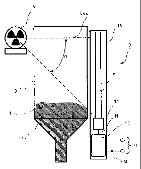
Fig. 1 shows schematically a measuring arrangement having a
radiometric measuring device. The radiometric measuring device
serves for measuring a physical, measured variable and for
outputting a measurement signal M, which corresponds to a
measured value of the physical, measured variable. The
measuring arrangement includes a container 3 fillable with a
fill substance 1. The radiometric measuring device is mounted
at the container 3. The physical, measured variable is e.g. a
fill level of the fill substance 1 in the container 3 or a
density of the fill substance 1.
The radiometric measuring device includes a radioactive radiator
5, which, during operation, sends radioactive radiation through
=
the container 3. The radiator 5 is composed e.g. of a radiation
protection container in which a radioactive preparation, e.g. a
Co 60 or Cs 137 preparation, is placed. The radiation
protection container has an opening, through which the radiation
escapes at an aperture angle alpha and irradiates the container
3.
The measuring device includes a detector 7, which serves for
registering radiation penetrating through the container 3 and
for detecting a radiation intensity dependent on the physical,
measured variable to be measured and for converting such into an
electrical output signal N. The detector 7 is a scintillation
detector having a scintillator 9, here a scintillation rod, and
. a photomultiplier 11 connected thereto. Scintillator 9 and
photomultiplier 11 are located in a protective tube 13
illustrated in Fig. 1, e.g. a tube =of stainless steel, which is
mounted on an outer wall of the container 3, lying opposite the
radiator 5. Radiometric radiatidn reaching the scintillator 9
= produces light flashes in the scintillation material. These are
registered by the photomultiplier 11 and converted into
electrical pulses, which are available as electrical output
signal N of the detector 7. The pulse rate, i.e. the number of
electrical pulses detected per unit time, is a measure for the
_ radiation intensity.
Connected to the detector 7 is a measuring device electronics
= 15, which serves. for producing, on the basis of the electrical
output signal N of the detector 7, the measurement signal M.
Energy supply of the radiometric measuring device occurs
exclusively via a single line-pair 17 connected to the measuring
= device electronics.15. Via line-pair 17, the measuring device
is connectable to a superordinated unit. Via =this line-pair 17,
7
CA 02703529 2010-04-22
also the measurement signal M generated by the measuring device
electronics 15 is made available by the measuring device.
For this, preferably one of the two standards set forth above
for 2-wire measuring devices is applied, i.e. the measuring
device controls either an electrical current flowing via the
line-pair 17 to a value, which corresponds to the present
measurement result, or the measuring device is connected to a
bus line and the measurement signal M is output in the form of a
bus signal corresponding to one of the standards usual for this,
such as e.g. Profibus or Foundation Fieldbus.
Fig. 2 shows a circuit diagram of the radiometric measuring
device of the invention, in which the detector 7, the thereto
connected measuring device electronics 15 and the line-pair 17
are presented.
The measuring device electronics 15 includes, connected to the
line-pair 17, a power supply 19, which supplies energy via a
first energy supply path 21 to the photomultiplier 11 and via a
second energy supply path 23 to a measuring, and control,
circuit 25. Applied in the first energy supply path 21 is an
energy storer 27, which is fed with energy from the line-pair 17
via the power supply 19. In the illustrated example of an
embodiment, the energy storer 27 is a capacitor connected to
ground or to a circuit zero point (circuit ground), which is
chargeable via the first energy supply path 21.
For producing the high voltages required for operating the
photomultiplier 11, a high voltage producing circuit 29 is
provided, which generates the required voltages by means of a
high voltage cascade 31. Fig. 3 shows example of an embodiment,
for this. The high voltage producing circuit 29 includes, input
side, a DC/AC converter 33, which is connected to the first
energy supply path 21 via a tap arranged between the energy
storer 27 and the power supply 19. The DC/AC converter 33
generates an alternating voltage, with which the high voltage
cascade 31 is operated. High voltage cascades are circuits,
which, by multiplication and rectification of an alternating
voltage, produce high direct voltages. They are known in the
literature, for example, under the name Cockcroft-Walton circuit
or Villard multiplier circuit and are based on a Villard
circuit, which, for this, is multiply connected one after the
other, thus cascaded. Each of the cascaded Villard circuits
includes two capacitors and two diodes, which are interconnected
with one another in the illustrated manner. The functional
principle of this high voltage cascade 31 is known from the
8
CA 02703529 2010-04-22
literature, and, consequently, not described here in detail.
Fig. 3 shows a six-stage, high voltage cascade 31, which is
constructed from six cascaded Villard circuits. On each stage,
a voltage tap UO, Ul, U2, U3, U4, U5 is provided. The uppermost
voltage tap UO is connected with a cathode K of the
photomultiplier 11, on which, in measurement operation, the
light flashes produced in the scintillator 9 by the radioactive
radiation impinge. The additional voltage taps Ul, U2, U3, U4,
U5 are, in each case, connected with a dynode D1, D2, D3, D4, D5
of the photomultiplier 11. Photoelectrons released from the
cathode K by the light pulses are accelerated and multiplied in
the electrical fields lying between the dynodes D1, D2, D3, D4,
D5. Then, they impinge on the anode A connected after the last
dynode D5 and flow via an analog pulse line 35 connected to the
anode A in the form of electrical current pulses. The analog
output signal of the anode A forms therewith the analog output
signal N of the detector 7. The output signal N is fed to the
measuring device electronics 15 via the analog pulse line 35 and
a trigger circuit 37 connected thereafter, which digitizes the
analog output signal N and forwards it via a digital pulse line
39 in the form of pulses P to a digital signal processor 41.
The digital signal processor 41 is, in the here illustrated
example of an embodiment, a component of the measuring, and
control, circuit 25. Core element of the measuring, and
control, circuit 25 is preferably a microcontroller 43, which
also performs the function of the signal processor 41.
The measuring, and control, circuit 25 includes a controller 45,
which, as a function of the energy available in measuring device
via the line-pair 17 and the energy storer 27, triggers
measuring phases, during which the measuring device measures the
physical, measured variable.
For this, the available energy in the device is registered.
This is accomplished, for example, via a measurement circuit 47,
which is connected to the line-pair 17 on the input side for
measuring the available input electrical current and input
voltage, and which provides the result to the measuring, and
control, circuit 25.
Alternatively or supplementally, for this, the total energy
available via the line-pair 17 and the energy storer 27 can be
registered via an energy measurement line 49, via which the
measuring, and control, circuit 25 is connected with a tap
arranged between the power supply 19 and the energy storer 27 in
the first energy supply path 21. The voltage applied to the
9
CA 02703529 2010-04-22
energy measurement line 49 is a measure of the charge status of
the energy storer 27, and is quantitatively registered via a
corresponding voltage measuring circuit 51 integrated in
measuring, and control, circuit 25 and made available to the
controller 45.
The function of the controller 45 is preferably likewise assumed
by the microcontroller 43 of the measuring, and control, circuit
25.
In a first variant of the invention, the available incoming
energy is measured via the measurement circuit 47, and the
controller 45 specifies, as a function of the available,
entering energy, measuring phases, during which the radiometric
measuring device measures. During measuring pauses, the energy
storer 27 is charged. In this case, the energy available in the
energy storer 27 supplementally to the entering energy is
derived, for example, on the basis of electrical current and
voltage of the entering energy and the charging and discharging,
characteristic curves of the energy storer 27 and taken into
consideration in the triggering of the measuring phases and the
dimensioning of the durations of the measuring phases and the
measuring pauses. In such case, the measuring phases have, for
example, a fixed, predetermined duration. They are, for
example, directly initiated, as soon as the incoming energy
together with that currently available in the energy storer 27
is sufficient therefor.
In a second variant, the triggering and the duration of the
measuring phases and the measuring pauses are established on the
basis of the total energy registered via the energy measurement
line 49 and available internally, as a whole, via the line-pair
17 and the energy storer 27. Also here the measuring phases
have, for example, a fixed predetermined duration, and they are,
for example, initiated, when the incoming energy together with
that currently available in the energy storer 27 are sufficient
therefor.
In a third variant, the measuring phases and the measuring
pauses are established as a function of the energy stored in the
energy storer 27. The stored energy can, in the illustrated
example of an embodiment, be derived, for example, on the basis
of the voltage across the capacitor, lying via the energy
measurement line 49 on the measuring, and control, circuit 25
and measured by means of the voltage measuring circuit 51. If
the stored energy is above a predetermined upper threshold
value, then the controller 45 initiates a measuring phase. The
CA 02703529 2010-04-22
duration of the measuring phase can be either fixedly
predetermined, or depend on the charge status of the energy
storer 27. In the second case, the controller 45 ends the
measuring phase, when the stored energy subceeds, or falls
beneath, a predetermined lower threshold value. The duration of
the measuring pause following thereon is ascertained by the time
required for the renewed charging of the energy storer 27.
The controller 45 operates the photomultiplier 11 exclusively
during the measuring phases. This is effected, in the
illustrated example of an embodiment, by an interrupter contact
53 installed in the first energy supply path 21 between the
energy storer 27 and the high voltage producing circuit 29.
Interrupter contact 53 is operated by the controller 45 via a
control line 55. During the measuring phases, the interrupter
contact 53 is closed and the photomultiplier 11 is supplied with
energy via the energy currently available via the line-pair 17
and the energy available in the energy storer 27. During the
measuring phase, the application of the high voltage cascade 31
effects, that only very low energy losses occur, since, in
contrast with the initially referenced resistance dividers,
practically no cross currents flow in the circuit. During the
measuring pauses, the high voltage producing circuit 29 (and
therewith also the photomultiplier 11) is switched off and
consumes no energy. In this time, the energy storer 27 is
charged via the energy available via the line-pair 17. If again
sufficient energy is available, the controller 45 can initiate
the next measuring phase. This can last, until the available
energy sinks below a predetermined limit value. Then, by the
opening of the interrupter contact 53, the next measuring pause
can be initiated. The high voltage cascade 31 offers the
advantage that it can be switched very rapidly on and off, since
it has only very low, internal capacitances.
For additional energy saving, the microcontroller 43 is
preferably switched off during the measuring pauses, or operated
with a reduced clocking rate.
During the measuring phases, the digital signal processor 41
ascertains, on the basis of the entering pulses P, the physical,
measured variable. For this, a pulse rate of the entering
pulses P is ascertained. Pulse rate is proportional to the
radiation intensity and therewith to the physical, measured
variable. The pulse rate is the number of pulses P entering per
unit time, and is, for example, ascertained by means of a
counter 57 and an internal clock 59 in the microcontroller 43.
11
CA 02703529 2010-04-22
Preferably, the duration of the measuring phases is dimensioned
in such a manner that during a measuring phase at least a
predetermined minimum number of pulses P enters and is available
for determining the pulse rate. In this way, statistical error
arising in the determining of the pulse rate can be limited.
The measuring device electronics 25 generates a measurement
signal M corresponding to the measured radiation intensity and
makes this available via the line-pair 17. This occurs, in the
illustrated example of an embodiment, via a transmitter 61, such
as e.g. a modem, inserted between the power supply 19 and the
measuring, and control, electronics 25.
In a first variant, the measurement signal M is output, as above
described, in the form of a bus signal and the transmitter 61 is
a bus modem, which cares for the communication via the line-pair
17 embodied as a data bus conductor. At the same time,
naturally also the energy supply of the total device occurs via
the data bus conductor.
In a second variant of the invention, the measurement signal M
is an electrical current I, which varies as a function of the
measured value between a minimum current 'min and a maximum
current 'max. In this case, the power supply 19, controlled by
the transmitter 61, sets an electrical current I flowing via the
line-pair 17. This electrical current I corresponds to the
measured value of the physical, measured variable to be
measured. This electrical current I is provided by the
superordinated unit (not shown) connected here to the measuring
device, and delivers the energy supply, with which the entire
measuring device is operated.
In the case of this variant, the duration of the measuring
phases is preferably based on the electrical current I
representing the measurement signal. In such case, the
electrical current I varies, as a function of the measured
value, between the minimum current Imin and the maximum current
Iõ,õõ, and the duration of the measuring phases increases with
increasing electrical current I.
Preferably, also the ratio of the duration of the measuring
phases to the duration of the measuring pauses is matched to the
electrical current I, so that the duration of the measuring
phases relative to the duration of the measuring pauses
increases with increasing electrical current I.
12
CA 02703529 2010-04-22
The ratio of the duration of the measuring phases referenced to
the duration of the measuring pauses is referred to as duty
cycle. This ratio is varied by means of the controller 45 as a
function of the available energy. Typically, the duty cycle
lies, dependent on the energy available via the line-pair 17
between 20 % and 100 %.
To the extent that sufficient energy is available, the measuring
device is preferably operated continuously with a duty cycle of
100 %. For this, for example, procedure is such, that the
available input voltage is measured e.g. with the measurement
circuit 47, and compared with a minimum voltage required for
continuous operation of the measuring device. If the input
voltage exceeds the minimum voltage required for continuous
operation, then the controller 45 initiates a measuring phase,
which it then ends, only when the input voltage sinks below the
minimum voltage.
Each radiometric measuring device has a measuring range for the
physical, measured variable to be measured, for which the
measuring device is designed. In the case of fill level
measurement, the measuring range is, for example, bounded by a
minimum fill level Lraln and a maximum fill level Lmax. In the
case of a classic fill level measurement, the radioactive
radiation is absorbed by the fill substance 1 in the container
3. Therewith, in the case of a full container 3, a low
radiation intensity falls on the detector 7, while, in the case
of an empty container 3, a markedly higher radiation intensity
falls on the detector 7.
In the case of density measurement, the measuring range is
bounded e.g. by minimum and maximum densities. Here,
analogously, in the case of fill substances with high density, a
smaller radiation intensity falls on the detector 7 than in the
case of fill substances with a lower density.
Preferably, for output of the measurement results, procedure is
such that associated with the minimum current is that
measured value, at which, within the predetermined measuring
range of the measuring device, the highest radiation intensity
is present. Referenced to the initially described standard for
2-wire measuring devices, this means that, for example,
associated with the minimum fill level Lnan is an electrical
current value of 4 mA and associated with the maximum fill level
Lmax is an electrical current value of 20 mA.
13
CA 02703529 2010-04-22
This offers the advantage, that, for measuring lower radiation
intensities, more energy is available than for measuring higher
radiation intensities. Correspondingly, lower radiation
intensities can be measured during longer measuring phases, or
with a higher duty cycle, than the higher radiation intensities.
The pulse rate to be measured in the case of high radiation
intensities is higher than in the case of low radiation
intensities. Correspondingly, a statistical measurement error
arising in the case of determining the pulse rate at high
radiation intensities is smaller than in the case of low
radiation intensities. The statistical fluctuations of the
pulse rate can be further reduced by special digital filters,
such as e.g. Kalman filters or median filters. In the case of
the example of an embodiment illustrated in Fig. 2, for this, a
digital filter 63 is provided associated with the signal
processor 41. A number of individual values of pulse rates
measured one after the other are input as input values into the
filter function. The filter weights the individual values
differently and ascertains, thereafter, the average value, or
the average value of the totality, of the individual values.
The longer the measuring phases last, the higher the number of
individual values can be selected, which are taken into
consideration for determining the pulse rate. In this way, the
statistical error is reduced. This positive effect is larger,
the smaller the pulse rate to be measured is.
For radiometric measuring devices of the invention, in the case
of which the measurement signal M is an electrical current I,
which varies between a minimum current Inun and a maximum current
'max as a function of the measured value, the electrical current
I is, at turn-on of the measuring device, preferably controlled
to the maximum current In
this way, the turn-on procedure,
wherein also the energy storer 27 is charged, is kept as short
as possible.
During calibration, the electrical current I is preferably
controlled to a value of more than 20.5 mA, especially to 22 mA.
An electrical current value of 22 mA for 2-wire measuring
devices is, according to standard, considered an error current,
and offers, in the case of the 2-wire device of the invention,
the advantage, that much energy is available in the device
during calibration.
In the case of the presence of a device error, the electrical
current is controlled to a value of less than 3.8 mA, especially
to 3.6 mA, which is likewise considered, according to standard
14
CA 02703529 2010-04-22
for this, to indicate error. According to the invention, the
controller 45 effects, during the presence of a device error, a
measuring pause lasting for the duration of the presence of the
device error.
CA 02703529 2010-04-22
List of Reference Characters
1 fill substance
3 container
radioactive radiator
7 detector
9 scintillator
11 photomultiplier
13 protective tube
measuring device electronics
17 line-pair
19 power supply
21 first energy supply path
23 second energy supply path
measuring, and control, circuit
27 energy storer
29 high voltage producing circuit
31 high voltage cascade
33 DC/AC converter
analog pulse line
37 trigger circuit
39 digital pulse line
41 digital signal processor
43 microcontroller
controller
47 measurement circuit
49 energy measurement line
51 voltage measuring circuit
_53 interrupter contact
control line
57 counter
59 clock
61 transmitter
63 digital filter
16