Note : Les descriptions sont présentées dans la langue officielle dans laquelle elles ont été soumises.
CA 02703917 2010-04-28
WO 2009/056792 PCT/GB2008/003462
1
DISPENSING VALVES
The present invention relates to dispensing valves for flowable material, such
as beverages, flowable foodstuffs, eg mustard and ketchup, and flowable
toiletries, such as moisturising cream.
The invention is concerned with such valves of the type comprising a valve
member of resilient polymeric material, in which at least one elongate
discontinuity is formed, the at least one discontinuity defining at least one
valve flap which is an integral part of the valve member but whose margin
defined by the discontinuity is not connected to the adjacent material of the
valve member, the valve flap being movable under the application of pressure
from a closed position, in which the adjacent margins of the discontinuity
form
a substantial seal, to an open position in which the margins of the
discontinuity
are spaced from one another and material can flow through the valve member.
The invention relates also to container closures incorporating such a
dispensing
valve and to a method of making such valves and closures.
Dispensing valves of the type referred to above are known and are disclosed in
e.g. US Patents Nos. 5033655, 5213236, 5377877 and 5409144. These known
valves include a valve member of silicone rubber in which there are two
elongate discontinuities in the form of two intersecting, perpendicular,
linear
cuts which define four valve flaps of segmental shape, the two linear edges of
each of which engage with an adjacent edge of an adjacent flap, when in the
closed position. The valve member is usually of concave shape and extends
into the interior of the container which it seals and in this position the
engaging
edges of the flaps form a seal. If the interior of the container is
pressurised, eg
by squeezing the wall of the container, if it is a resilient material, the
pressure
CA 02703917 2010-04-28
WO 2009/056792 PCT/GB2008/003462
2
causes the valve member to move into a convex configuration, in which it may
extend slightly out of the container. The pressure causes the valve flaps to
move pivotally about the lines along which they are connected to the remainder
of the valve member into an open position, thereby creating an opening through
which the content of the container may flow. When the pressure is relaxed, the
flaps return under their own resilience to the sealed position and the valve
member returns to its concave configuration.
Such valves are very effective and have an enjoyed wide commercial success.
However, the use of silicone rubber is also associated with a number of
disadvantages. Thus the surface of components made from silicone rubber is
tacky and thus has a very high coefficient of friction and this means that
handling and working with such components is problematic. Furthermore, the
valve has to be connected in some manner to a container closure, eg a bottle
lid, because it is of course not possible to make the entire closure from
silicone
rubber. However, this is a difficult process, particularly as silicone rubber
cannot be heat fused, and the additional steps involved add significantly to
the
overall manufacturing costs. Furthermore, the resultant container closure then
necessarily comprises quite different materials connected together and this is
a
significant problem as regards recycling the container and closure after use.
These problems are partially addressed by WO 99/08942 in which the valve
member is made of thermoplastic material. This material may be easily
handled and is heat sealable and the valve member may therefore be connected
to a container closure by a heat sealing process, which is relatively rapid
and
simple. However, it is still necessary to make the valve member separate from
the remainder of the container closure and then to connect these two
components together. This is not only time-consuming and expensive but also
still results in a composite container closure made of two different
materials.
CA 02703917 2010-04-28
WO 2009/056792 PCT/GB2008/003462
3
FR-A-2690139 discloses a valve member made of polyethylene or
polypropylene which is formed with an elongate area of reduced thickness by
virtue of the provision of an elongate recess in its internal surface. The
thickness of the area of reduced thickness progressively decreases to a
minimum towards one side. Pressure is applied by a tool to the internal
surface
of the portion of reduced thickness, which is thus caused to rupture along the
one side to form a slit. The ruptured edge of the portion of reduced thickness
is
stretched by the rupturing to form a lip and thus subsequently overlies the
opposite edge of the slit. Due to the fact that the rupturing occurs along one
side edge of the recess, the opposite edge of the slit does not have a similar
lip.
However, only a single straight rupture line is formed and thus no movable
valve flap is defined. In each of the first, third and fourth embodiments
disclosed, the rupture line extends over the apex or around the periphery of a
conical dispensing head and the rupture line is thus bent or curved. This
means
that the valve member thus does not have a valve flap which is movable with
respect to the remainder of the valve and thus the valve is in fact incapable
of
dispensing any material. The second embodiment shown in Figures 5 and 6
has two elongate areas of reduced thickness, which intersect in a cruciform
shape and each of which is of reducing thickness towards a long side.
Although the specification refers to rupturing the valve along the lines of
minimum thickness to form elastic flaps it also refers to forming two sets of
perpendicular slits 14 along angles 18 and it is therefore clear that
rectangular
cruciform resilient valve flaps are not formed. Although two triangular areas
partially defined by two perpendicular rupture lines are formed, the fact that
the
lines connecting the ends of the two sets of rupture lines are necessarily
curved,
due to the fact that the areas of reduced thickness are formed on a domed
dispensing head, means that pivotal movement of these triangular areas is
impossible and thus that no material can in fact be dispensed. It is,
therefore,
CA 02703917 2010-04-28
WO 2009/056792 PCT/GB2008/003462
4
clear that this prior document is in fact only a "paper publication" and that
the
valve it purports to disclose will not in fact operate as a valve at all. Even
if the
rupturing process were to produce movable valve flaps capable of dispensing
material from a container, the fact that only one marginal edge of the or each
ruptured slit is elongated to form a lip which overlies the other edge means
that
no air could be admitted into the container to replace dispensed material and
thus would mean that the valve would operate only as a one-way valve and not
a two-way valve and thus that the container would progressively collapse as
material is dispensed and this is highly undesirable in many cases.
It is therefore the object of the invention to provide a dispensing valve of
the
type referred to above and a one-piece container closure incorporating such a
dispensing valve which uses only cheap and readily available materials and
may be produced rapidly and cheaply in a single process and does not require
the subsequent connection of the dispensing valve to a container closure. It
is a
further object to provide such a valve which will act as a two-way valve and
will thus permit material to leave the container and air to enter it.
According to the present invention, a dispensing valve the type referred to
above is characterised in that the valve member is of polyolefin material,
that
the at least one discontinuity is a rupture line and that the two margins
defining
the rupture line are of decreasing thickness towards their free edge and
overlie
one another.
Thus the valve in accordance with the invention is fundamentally different to
the known valves of the type disclosed in the U.S. patents referred to above
in
that the or each elongate discontinuity is a rupture or tear line and not a
clean
cut. The manner in the material of the valve member is ruptured will be
described in detail below. However, since polyolefins are inherently somewhat
CA 02703917 2010-04-28
WO 2009/056792 PCT/GB2008/003462
waxy, the rupturing process permanently deforms or stretches the plastic
material along the rupture line before the actual rupture process occurs. This
stretching process will inherently result in a local reduction in thickness of
the
valve member and rupture of the material occurs when the thickness locally
5 becomes zero. After rupture has occurred, both the adjacent margins will be
of
decreasing thickness towards their free edge and one will necessarily somewhat
overlie the other.
The inherent resilience of the polyolefin material will result in a contact
pressure between the overlying margins of the discontinuity and the waxy
surface quality of the material ensures that the contacting surfaces form a
reliable seal. In order to ensure that the surface of the material has a
degree of
waxiness which optimises the integrity of the seal whilst ensuring that the
contacting surfaces do not stick together, it is preferred that the melt flow
index
of the polyolefin material is between 10 and 45 g/10 minutes.
In use, the valve is applied to a flowable material container. When the
pressure
within the container is increased, e.g. by compressing its outer wall, the
pressure acts on the valve flap and moves it away from the remainder of the
valve member so as to create an opening through which the flowable material
can then pass. The movement of the valve flap will be in rotation about an
axis
or integral hinge defined by a line extending between the adjacent ends of the
or each discontinuity defining the valve flap. In order to ensure that the
valve
flap is moved adequately by the pressure that is applied to it and that, when
it
returns to its original position under the resilience of its integral hinge,
its
margins engage the margins on the other side of the or each discontinuity with
an adequate contact pressure to create a reliable seal, it is important that
the
polyolefin material has an appropriate resilience and that the integral hinge
has
CA 02703917 2010-04-28
WO 2009/056792 PCT/GB2008/003462
6
an appropriate thickness. It is preferred that the flexural modulus of
elasticity
of the integral hinge is between 200 and 1400.
It is found that the bending characteristics of the integral hinge are more
predictable and reproducible if the valve plate is provided with a line of
reduced thickness extending between the ends of the or each discontinuity
defining the valve flap which defines the position of the integral hinge. The
precise stiffness of the integral hinge may be set by precisely controlling
the
thickness of the integral hinge. The valve member is typically a plate with a
thickness between 0.5 and 1.5mm and the integral hinge is typically defined by
a grove or line of reduced thickness and has a thickness of between 0.1 and
0.5mm, preferably between 0.2 and 0.3mm. In its simplest form, the valve
member will have only a single discontinuity in it, e.g. generally of U-shape,
so
that the valve includes a single valve flap which is defined by the
discontinuity
and is connected to the remainder of the valve member along a line which
extends between the two ends of the discontinuity. It may perhaps also be
possible for there to be two perpendicular intersecting discontinuities in the
manner similar to the prior art. However, this would result in four valve
flaps
connected to the valve member by relatively long integral hinges and the
greater stiffness of polyolefin material as compared to silicone rubber may
make this impractical. Furthermore, this would result in the movable margin of
each valve flap cooperating with and intended to form a seal with a movable
margin of the two adjacent flaps. It is found in practice that a more reliable
seal is formed if the margin of the or each valve flap cooperates, at least
over
the majority of its length, with a margin formed on a stationary portion of
the
valve member and not on another valve flap.
In the preferred embodiment, there are four valve flaps arranged in a
generally
cruciform shape, each valve flap being of generally rectangular shape and
CA 02703917 2010-04-28
WO 2009/056792 PCT/GB2008/003462
7
being integrally connected to the valve member at its outer end. The four
valve
flaps may cooperate with one another in a variety of different ways but it is
preferred that the margin of the inner end of each valve flap cooperates with
the
margin of the inner end of two adjacent valve flaps.
As mentioned above, the valve member is made of polyolefin material,
preferably polypropylene or polyethylene, both of which are cheap and readily
available materials. These materials are very suitable for making container
closures, e.g. bottle caps and the like, and this therefore opens up the
possibility
1.0 of providing a one-piece container closure incorporating such a dispensing
valve. Such a closure is in practice likely to be a unitary injection moulded
component and will consist of a closure plate, which, in use, will extend over
the mouth or dispensing opening of a container for flowable material, integral
with which is a peripheral depending skirt for attachment to the container,
the
closure plate constituting the valve member.
The invention also embraces a method of making such a dispensing valve and
thus according to a further aspect of the prevent invention a method of
manufacturing a dispensing valve for flowable material comprises injecting
hot, flowable polyolefin material into a mould cavity, which is partially
defined
by a first mould member on one side and a second movable mould member on
the other side, the second mould member including a relatively movable
rupture member, to form a valve member, forming one or more first elongate
recesses in a surface, which is defined by the second mould member, of the
valve member constituting one or more first lines of reduced thickness,
permitting the polyolefin material to cool and solidify, moving the second
mould member relative to the first mould member to create a gap, advancing
the rupture member against the valve member to cause it to rupture along the
first lines of reduced thickness and ejecting the valve member.
CA 02703917 2010-04-28
WO 2009/056792 PCT/GB2008/003462
8
Thus, the valve in accordance with the invention is produced by a conventional
injection moulding process. The mould cavity is defined, at least in part, by
a
first mould member and a second mould member on which one or more
elongate projections or beads are formed. Hot polyolefin material is then
injected into the mould cavity so as to form a valve member and the elongate
projection or bead on the movable mould member will necessarily form one or
more lines of reduced thickness in one surface of the valve member. The
polyolefin material is then permitted to cool and solidify and whilst it is
relatively warm the movable mould member is moved relative to the first
mould member to create a gap. The rupture member is then advanced towards
the valve member and this causes the portion of the valve member in which the
or each line of reduced thickness is formed to deform and ultimately to tear
or
rupture along the lines of reduced thickness. The lines of reduced thickness
are
arranged such that the rupturing process will produce one or more valve flaps
which are separated from the remainder of the valve member around much of
their periphery but are integrally connected to it along a hypothetical line,
which extends between the ends of the rupture lines or adjacent pairs of ends
of
the rupture lines, and this line will constitute an integral hinge about which
the
valve flap may pivot relative to the remainder of the valve member. The
rupturing process will inherently result in localised stretching of the
polyolefin
material and this means that the margins of each discontinuity will not simply
abut laterally against one another, as is the case when the discontinuity is
formed by a cutting process, but will overlie one another to a certain extent.
The overlying margins are of a material which inherently has a somewhat waxy
surface character and they therefore form a seal. The fact that the valve flap
was ruptured out of the material surrounding it means that it is inherently a
perfect fit in the hole which it occupies.
CA 02703917 2010-04-28
WO 2009/056792 PCT/GB2008/003462
9
As mentioned above, the or each valve flap will be connected to the remainder
of the valve member along a hypothetical line which will constitute an
integral
hinge. This integral hinge will operate more effectively and in a manner which
is readily predeterminable if it is defined by a second line of reduced
thickness.
The material thickness along the second line of reduced weakness is, however,
preferably greater than that along the first line or lines of reduced
thickness and
this will of course ensure that the first lines of reduced thickness rupture
whilst
the second lines of reduced thickness do not. It is therefore preferred that
the
one or more first lines of reduced thickness define an elongate area which is
integrally connected to the remainder of the valve member along a hypothetical
line and that the method includes forming a second elongate recess along the
said line to form a second line of reduced thickness along the said line, the
second elongate recess having a smaller depth than the first elongate recess.
It is preferred that the ultimate valve has two or more valve flaps and the
method therefore preferably includes forming a plurality of first elongate
recesses to define a plurality of elongate areas and moving a respective
rupture
member against each elongate area to cause it to rupture along the first lines
of
reduced thickness. Each valve flap is therefore ruptured or torn free of the
surrounding material by a respective rupture member and of course left
connected to the remainder of the valve member by a respective integral hinge,
which is preferably defined by a second line of reduced thickness. In the
preferred embodiment, four elongate areas arranged in the cruciform shape are
formed and the method includes forming a second line of reduced thickness at
the outer end of each elongate area.
In order to ensure that the polyolefin material is sufficiently soft and
ductile to
be ruptured relatively easily, it is preferred that the polyolefin material is
permitted to cool in the mould cavity to a temperature of between 40 C and
CA 02703917 2010-04-28
WO 2009/056792 PCT/GB2008/003462
70 C before advancing the or each rupture member against the valve member
to rupture it along the first lines of reduced thickness.
Further features and details of the invention will be apparent from the
5 following description of one specific method of manufacturing a container
closure cap incorporating a dispensing valve in accordance with the invention
which is given by way of example only with reference to the accompanying
drawings, in which:
10 Figure 1 is a partial sectional view of an injection mould for making a
closure
cap in accordance with the invention shown in the open position before
rupturing the lines of reduced thickness;
Figure 2 is an enlarged view of part of Figure 1 shown during rupturing of the
lines of reduced thickness;
Figure 3 is an end view of the inner core of the injection mould;
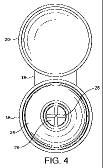
Figure 4 is a plan view of the closure cap produced in the injection mould;
Figure 5 is a vertical sectional view of a modified construction of closure
cap;
Figure 6 is a plan view of the cap of Figure 5;
Figures 7 and 8 are partial sectional views along the line 7-7 and 8-8,
respectively, in Figure 6; and
Figure 9 is a perspective view of a further modified closure cap.
CA 02703917 2010-04-28
WO 2009/056792 PCT/GB2008/003462
11
The injection mould shown in Figures 1 to 3 consist of a fixed mould portion 2
and a movable mould portion 4. The fixed mould portion 2 includes a molten
plastic injection nozzle 6 and a stationary core 8. The movable mould portion
4 includes a core which comprises an inner core 8 surrounded by an outer core
10 and is surrounded by a stripper ring 12. The movable mould member also
includes an ejector rod 14. When the two mould portions are moved together
they define a closed mould cavity defining the shape of a closure cap
comprising a cap portion 16 connected by an integral bridge 18 to a cover
portion 20. The cap portion comprises a cylindrical side wall 22, integral
with
whose inner surface is a screwthread for connection with a corresponding
screwthread on the external surface of the neck of a bottle or other container
and integral with one end of which is a generally inwardly extending annular
flange 24. Integral with the inner edge of the annular flange 24 is a
substantially planar element constituted by a plate 26 in which four movable
valve flaps 28 are defined, as will be described below.
Longitudinally movably accommodated within the inner core 8 are four rupture
pins 30, only one of which is shown in Figure 1 for the sake of clarity, each
of
which is movable between a retracted position, in which its end surface is
flush
with the end surface of the inner core, and an extended position in which it
extends slightly beyond the end surface of the inner core. As may be seen in
Figure 2, the end surface of the inner core is slightly conical. As may be
best
seen in Figure 3, extending around the conical end surface of the inner core 8
is
a bevel or chamfer 32. Situated centrally within the end surface are four
openings, each of which constitutes the end of a respective passage
accommodating an ejector pin 30, the shape of which precisely matches that of
the openings. The four openings and thus the four ejector pins 30 are of
rectangular shape with the four rectangles being arranged in a cruciform shape
offset from one another by 90 . At the inner end of each rectangle is a
CA 02703917 2010-04-28
WO 2009/056792 PCT/GB2008/003462
12
triangular extension and the apexes of the four triangles meet at a single
point.
Extending along each longitudinal side of each rectangular portion of the
opening is an elongate upstanding formation or bead 34 of triangular cross-
section, the height of which is about 0.6mm. Each bead 34 associated with
each opening meets a bead 34 associated with another opening to define a
junction 36 and there are therefore four such junctions arranged in a square
configuration. Extending between each diagonally opposed pair of junctions is
a further triangular upstanding bead 38. The two beads 38 intersect at right
angles at their centre. Extending along the outer end of each rectangular
opening is a further upstanding bead 40, generally similar to the bead 34 but
lower, that is to say in this case with a height of about 0.3mm.
In use, the injection mould is closed and molten polyolefin material is
injected
through the injector 6 into the mould cavity to form the cap portion 16
connected by the integral bridge 18 to the cover 20. The beads 34, 38, 40
produce lines of reduced thickness in the underside of the plate 24, the shape
and arrangement of which of course corresponds precisely to those of the
beads. The moulding is then allowed to cool and solidify until it reaches a
temperature of between about 40 C and 70 C, that is to say the plastic
material
is still warm and thus relatively soft, and the movable mould portion 4 is
then
moved away from the fixed mould portion 2 into the position shown in Figure
2. The four rupture pins 30 are then advanced slightly, as shown in Figure 2.
Their end surfaces correspond to the area within the beads 34 and 40 and this
causes the material within those beads to deform out of the plane of the plate
26. The end surfaces of the pins 30 match the conical shape of the end surface
of the core 8 and the deforming force supplied by the pins therefore acts
preferentially in the centre of the plate 26. As the plastic within the areas
defined by the lines of reduced thickness is deformed upwardly, the material
of
the lines of reduced thickness begins to stretch and its thickness decreases.
The
CA 02703917 2010-04-28
WO 2009/056792 PCT/GB2008/003462
13
thickness of the lines of reduced thickness formed by the beads 40 does not,
however, decrease significantly, firstly because the force supplied to them is
less due to the conical shape of the ends of the rupture pins and secondly
because their material thickness is greater than that of the lines of reduced
thickness formed by the beads 34 and 38. As the lines of reduced thickness
formed by the beads 34 and 38 stretch, their thickness decreases progressively
until it reaches zero, at which point rupture occurs. Four valve flaps 28 are
thus formed, each of which has a shape defined by the rupturing which occurs
along the lines of reduced thickness created by two parallel beads 34, the
associated bead 40 and the two associated beads 38. Each valve flap 28
remains, however, connected to the plate 26 by the line of reduced thickness
created by the associated bead 40, which now constitutes an integral hinge. As
a result of the stretching which occurred at the lines of reduced thickness
prior
to rupture, the margins of each valve flap will no longer neatly abut the
adjacent margins of the hole formed in the plate but will instead overlie
those
margins.
Whilst the valve flaps are formed by rupturing, the closure cap is retained in
position on the movable mould member because its cylindrical side wall 22 is
retained captive. Once the rupturing process is complete, the stripper ring 12
is
advanced and due to the fact that a portion of the stripper ring engages the
free
end surface of the cylindrical side wall 22, this results in the moulded cap
being
forced free of the movable mould member. The moulded cap then has the
appearance shown in Figure 4. The cap portion may then be screwed to a
bottle or other container for flowable material and the cover portion 20 may
be
pivoted using the bridge or integral hinge 18 into a position on top of the
cap
portion, where it may be retained by e.g. a snap fit. It will be appreciated
that
the cover portion is not essential and merely serves as a dust protector and
to
enhance the aesthetic appeal of the closure.
CA 02703917 2010-04-28
WO 2009/056792 PCT/GB2008/003462
14
As mentioned above, the margins of the valve flaps 28 will overlie the margins
of the apertures in the plate 26 at their outer ends and will overlie, or be
overlain by, the margins of the adjacent flaps at their inner ends. Since this
would mean that the valve flaps are deformed slightly out of the plane of the
plate 26, the resilience of polyolefin material at the lines of reduced
thickness
formed by the beads 40 will mean that this contact is under pressure. Due to
the inherently waxy surface quality of polyolefin material, this means that a
reliable seal is formed. If the container is now inverted and pressure applied
to
its side wall to pressurise the contents, the flaps are caused to rotate
outwardly
about their integral hinges, thereby opening the container and permitting
dispensing of its contents. If the container is now returned to its original
orientation, the valve flaps will return to their original position under the
resilience of the integral hinges and the seal of the container will be
recreated.
The modified embodiment of closure cap shown in Figures 5 to 8 is very
similar to that shown in Figure 4, but in this case no lid portion is
provided.
The cylindrical side wall 22 for connection to the bottle is integrally
connected
to a further cylindrical portion 50 of smaller diameter and it is this latter
cylindrical portion 50 which carries the plate 26 from which the valve flaps
are
formed.
Figures 7 and 8 are cross-sectional views which show how the stretched
margins of the valve flaps overlie one another and the margins of the holes
formed in the plate 26 by the rupturing process. It is in practice immaterial
which margin overlies the other and it will be understood that, in use, this
may
be frequently reversed but this has no adverse effect on the function.
CA 02703917 2010-04-28
WO 2009/056792 PCT/GB2008/003462
Figure 9 is a perspective view of a further embodiment of closure cap in
accordance with the invention which differs from the preceding embodiments
only in details which are immaterial to the invention. It has, however, been
included because it shows the valve flaps in the open position, which they
5 adopt when flowable material is being poured from the container.
In a further modified embodiment, which is not illustrated, each valve flap is
connected to the remainder of the lid by a respective hinge of so-called "bow
tie" type. Such hinges are known per se and consist of a number of integral
10 hinge lines and cut lines and serve to increase the force acting on the
valve
flaps tending to return them to the closed position. The use of such hinges
will
further increase the sealing integrity of the valve flaps in the closed
position.