Sélection de la langue

Search

Sommaire du brevet 2704822 

Énoncé de désistement de responsabilité concernant l'information provenant de tiers

Une partie des informations de ce site Web a été fournie par des sources externes. Le gouvernement du Canada n'assume aucune responsabilité concernant la précision, l'actualité ou la fiabilité des informations fournies par les sources externes. Les utilisateurs qui désirent employer cette information devraient consulter directement la source des informations. Le contenu fourni par les sources externes n'est pas assujetti aux exigences sur les langues officielles, la protection des renseignements personnels et l'accessibilité.

Disponibilité de l'Abrégé et des Revendications

L'apparition de différences dans le texte et l'image des Revendications et de l'Abrégé dépend du moment auquel le document est publié. Les textes des Revendications et de l'Abrégé sont affichés :

  • lorsque la demande peut être examinée par le public;
  • lorsque le brevet est émis (délivrance).
(12) Brevet: (11) CA 2704822
(54) Titre français: PROCEDE ET DISPOSITIF DE DETERMINATION DU DEBIT D'UN FLUIDE EN ECOULEMENT
(54) Titre anglais: METHOD AND APPARATUS TO DEFINE THE VELOCITY OF A FLOWING LIQUID
Statut: Périmé et au-delà du délai pour l’annulation
Données bibliographiques
(51) Classification internationale des brevets (CIB):
  • G01F 01/68 (2006.01)
(72) Inventeurs :
  • VERJUS, CHRISTOPHE (Suisse)
  • RENEVEY, PHILIPPE (Suisse)
  • NEUMANN, VICTOR (Suisse)
(73) Titulaires :
  • DIGMESA AG
(71) Demandeurs :
  • DIGMESA AG (Suisse)
(74) Agent: AVENTUM IP LAW LLP
(74) Co-agent:
(45) Délivré: 2016-09-20
(86) Date de dépôt PCT: 2008-11-13
(87) Mise à la disponibilité du public: 2009-05-22
Requête d'examen: 2013-10-31
Licence disponible: S.O.
Cédé au domaine public: S.O.
(25) Langue des documents déposés: Anglais

Traité de coopération en matière de brevets (PCT): Oui
(86) Numéro de la demande PCT: PCT/EP2008/009579
(87) Numéro de publication internationale PCT: EP2008009579
(85) Entrée nationale: 2010-05-05

(30) Données de priorité de la demande:
Numéro de la demande Pays / territoire Date
10 2007 054 186.6 (Allemagne) 2007-11-14

Abrégés

Abrégé français

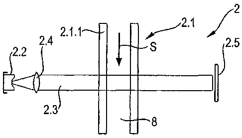
Pour déterminer avec une haute précision et une mise en oeuvre technique minimale, et en particulier une mise en oeuvre minimale d'appareils, le débit d'écoulement d'un liquide dans un tube, l'invention propose un procédé et un dispositif de détermination du débit d'un écoulement de liquide, le procédé prévoyant de chauffer le liquide au moyen d'un faisceau optique de chauffage, de faire traverser l'emplacement chauffé par un faisceau optique de détection, les axes optiques du faisceau de chauffage et du faisceau de détection coïncidant au moins sur le site du chauffage et le faisceau de détection étant enregistré au moyen d'une batterie de détecteurs, le dispositif étant configuré de telle sorte que le système qui chauffe une partie intérieure délimitée du liquide et un ensemble optique qui guide le faisceau du laser sont disposés de telle sorte qu'un faisceau de mesure traverse la partie chauffée à l'emplacement exact de son chauffage.


Abrégé anglais


In order to determine the through put of a fluid flow in a pipe with a minimum
of technical and particularly equipment
expense, the invention proposes a method and a device for determining the
throughput of a fluid flow, wherein the method provides
for the fluid to be heated by means of an optical heating beam and for the
heating site to be irradiated by an optical detection beam,
wherein the optical axes of the heating and detection beams correspond at
least at the heating site, and the detection beam is recorded
by a detector array; and the device is designed such that the unit for heating
an inner region of an adjacent inner region of the fluid
and an optical arrangement guiding the beam of the laser are disposed such
that a measurement beam passes through the heated
region at the absolute location of the heating thereof.

Revendications

Note : Les revendications sont présentées dans la langue officielle dans laquelle elles ont été soumises.


17
CLAIMS
What is claimed is:
1. A method for determining a flow of a flowing fluid, the method comprising
the steps
of:
heating the flowing fluid by means of an optical heating beam, said optical
heating beam being intensity-modulated or pulsed;
irradiating a heating location by at least one optical detection beam, wherein
optical axes of the optical heating beam and the at least one optical
detection beam
coincide at least at the heating location, the at least one optical detection
beam being
absorbed by an array of detectors, wherein an angle between said optical
heating beam
and said at least one optical detection beam is zero at least at said heating
location, said
array of detectors carrying out a plurality of temporally successive
measurements during
heating; and
determining at least a statistical moment of a variance of said at least one
optical
detection beam influenced by said heating location, wherein a time profile of
a refractive
index of said heating location in the flowing fluid is determined based on
said plurality of
temporally successive measurements.
2. A method according to claim 1, wherein the optical heating beam and said at
least one
optical detection beam are emitted from a same radiation source.
3. A method according to claim 1, wherein the optical heating beam and said at
least one
optical detection beam are emitted from different radiation sources.
4. A method according to any one of claims 1 to 3, wherein the at least one
optical
detection beam has a greater mean diameter than the optical heating beam.
5. A method according to any one of claims 1 to 4, wherein one or more of the
optical
heating beam and said at least one optical detection beam are optical beams or
laser

18
beams focused on a region inside the flowing fluid.
6. A method according to any one of claims 1 to 4, wherein one or more of the
optical
heating beam and said at least one optical detection beam are parallel beams.
7. A method according to any one of claims 1 to 4, wherein one or more of the
optical
heating beam and said at least one optical detection beam are modulated
optical beams.
8. A method according to any one of claims 1 to 7, wherein a detection of said
at least
one optical detection beam is carried out by means of a linear array of
detectors.
9. A method according to any one of claims 1 to 7, wherein a detection of said
at least
one optical detection beam is carried out by means of a planar, two-
dimensional array of
detectors.
10. A method according to any one of claims 1 to 9, wherein the flow is
determined from
a received profile of the at least one optical detection beam.
11. A method according to any one of claims 1 to 10, wherein a flow velocity
of the
flowing fluid is determined by determining a decrease in statistical moments.
12. A method according to any one of claims 1 to 11, wherein determining said
at least a
statistical moment of the variance of said at least one optical detection beam
includes
determining one or more of mean value, variance, skewness and kurtosis.
13. A method according to claim 12, wherein a shift in the mean value of a
position of the
at least one optical detection beam is determined as a measure for the flow.
14. A method according to claim 12, wherein a modification of the variance of
the at least
one optical detection beam is determined with the flow.

19
15. A method according to any one of claims 1 to 14, wherein an intensity of
the at least
one optical detection beam is modulated and a phase shift of the modulated
intensity and
of a measurement is determined.
16. A method according to claim 15, wherein the at least one optical detection
beam is
modulated with a plurality of frequencies.
17. A method according to claim 15, wherein the at least one optical detection
beam is
stochastically modulated.
18. An apparatus for determining a flow of a flowing fluid, the apparatus
comprising:
a tube, through which the flowing fluid flows, said tube having a wall, which
is at
least partially transparent for an optical detection beam;
a device for heating at least a location inside the flowing fluid, said device
generating an optical heating beam, said optical heating beam being intensity-
modulated
or pulsed;
a laser for generating the optical detection beam; and
an electronic evaluation device, wherein the device for heating at least the
location inside the flowing fluid and an optical arrangement guiding the
optical detection
beam of the laser are positioned in such a way that the optical detection beam
irradiates
the heated location, said optical heating beam being located at an angle of
zero with
respect to said optical detection beam at least in said heated location,
wherein an array of
detectors is provided for receiving the optical detection beam, and the
evaluation device
is configured for determining at least a statistical moment of a variance of
said optical
detection beam influenced by said heating location, said array of detectors
carrying out
successive measurements during heating, wherein a time profile of a refractive
index of
said heated location in the flowing fluid is determined based on said
successive
measurements.
19. An apparatus according to claim 18, wherein the device for heating the
flowing fluid
is a laser.

20
20. An apparatus according to claim 18 or 19, wherein the laser, which
produces the
optical detection beam, is also the device for heating the flowing fluid.
21. An apparatus according to claim 20, wherein the optical arrangement is
such that the
optical detection beam and the heating beam is not split when transmitted
through the
flowing fluid.
22. An apparatus according to any one of claims 18 to 21, wherein said optical
arrangement comprises a focusing lens for focusing said optical heating beam
and said
optical detection beam inside the flow of the flowing fluid.
23. An apparatus according to any one of claims 18 to 21, wherein said optical
arrangement comprises a lens for parallelizing the optical detection beam and
irradiating
the flowing fluid by means of the parallelized optical detection beam.
24. An apparatus according to any one of claims 18 to 23, wherein the laser is
a
modulated laser.
25. An apparatus according to any one of claims 18 to 24, wherein the
apparatus is
configured for taking a plurality of temporally sequential measurements.
26. An apparatus according to claim 24 or 25, wherein the apparatus is
configured for
taking a plurality of temporally sequential measurements during a laser pulse.
27. An apparatus according to any one of claims 18 to 26, wherein the array of
detectors
is a linear array of detectors.
28. An apparatus according to any one of claims 18 to 26, wherein the array of
detectors
is a planar, two-dimensional array of detectors.

21
29. An apparatus according to any one of claims 18 to 28, wherein the
electronic
evaluation device is configured for determining statistical moments of
received signals,
said statistical moments being one or more of mean value, variance,
statistical skewness
and kurtosis.
30. A method for determining a flow of a flowing fluid, the method comprising
the steps
of:
heating a fluid by an optical heating beam;
irradiating a heating location with at least one optical detection beam,
wherein
optical axes of the optical heating beam and said at least one optical
detection beam
coincide at least at the heating location, the at least one detection beam
being absorbed by
an array of detectors, wherein said heating beam is parallel to said at least
one detection
beam at least at said heating location, said array of detectors carrying out a
plurality of
successive measurements during heating; and
determining a time profile of a refractive index of said heating location in
the
flowing fluid determined based on said plurality of successive measurements.
31. A method according to claim 30, further comprising:
determining at least a statistical moment of a variance of said at least one
detection beam influenced by said heating location.

Description

Note : Les descriptions sont présentées dans la langue officielle dans laquelle elles ont été soumises.


CA 02704822 2010-05-05
Method and apparatus to define the velocity of a flowing
liquid
This invention is about a method and apparatus to define
the velocity of a flowing liquid.
Other generic kind of procedures and systems of different
makes are known.
Therefore it is known that the deflection of a - small -
laser beam which is sent through a heated zone of a liquid
can be used to measure the velocity of the liquid. The
heated zone of the liquid is warmed up by a different de-
vice than the laser.
Alternatively, it is known how to measure the flow velocity
of a liquid if necessary by means of a down-stream array of
optical detectors and an optically produced heating point
during the running time of a temporarily heated area from
the heating point to the measuring point.
2008199141

CA 02704822 2010-05-05
2
Disadvantageously, in this case two different workspace lo-
cations as well as working equipments are needed: the heat-
ing system and the heating detection system. The invention
has therefore the aim to develop an improved procedure as
well as a developed apparatus to define the velocity of a
flowing liquid and to avoid the disadvantages mentioned be-
fore.
In accordance with an invention like the one initially men-
tioned the requirement named before is solved that way that
the liquid will be heated by means of an optical heating
ray. The heating spot will be radiated by an optical detec-
tion ray. The optical axis of the heating ray and the de-
tection ray will at least correspond in the heating spot.
The detection ray will be taken by an array of detectors.
To fulfil the above mentioned requirement the invention
will include an apparatus in which the device to heat a
limited area of the interior of the liquid (8) and an opti-
cal device (2.4, 2.6) to guide the optical beam (2.3) of
the laser (2.2) are positioned such that a measuring beam
(2.3) radiates the heated area in its absolute point of
heating.
Flow defines one for this typical dimension, like rate of
flow, velocity, volume flow rate and similar. By partly ab-
sorbing an optical beam, e.g. a laser beam, in the liquid,
especially in water which absorbing coefficient is 0,46 m-1
accordingly to a wave length of 970 mm a thermical lens
will be produced in the heated area. The lens and espe-
cially its flow inducing properties are measured to define
the flow velocity of the liquid. The measurement is taken
by means of the not-absorbed light of the same laser beam

CA 02704822 2010-05-05
3
so that the initial beam and the measuring beam coincide.
This method is a non-invasive, contact free thermical meas-
uring method of the heat induced modifications of the opti-
cal properties of the heated fluid. The measurement is
taken at the same point as the absolute heating point: i.e.
heating point and measuring point coincide or overlap in
the area. The detection of the laser beam takes place by an
array of detectors with a few single-detectors (at least
two) but at the same time a number of single-detectors col-
lect the light of the light beam. Apart from the diffusion
by the heat induced thermical lens, this procedure can be
expanded by means of an additional lens or a group of opti-
cal lenses which are positioned outside and in front of the
tube of the array of detectors. Herewith different proper-
ties of the heated area can be collected and not only its
displacement (movement) but also its deformation, i.e.
changes of the shape within the heated zone which result
from the flow movement. In accordance with the invention
the measurement is not just calculated by a global deflec-
tion of the light ray but a global measurement of a wider
area is taken and therewith its flow induced properties,
especially its deformations. The liquid is heated (contact
free) by means of an optical beam. Especially the beam with
its light irradiating through and which heats the liquid is
detected.
In accordance with the preferred arrangement it is planed
that the heating beam and the detector beam are sent by the
same source or that they arise out of different sources. In
the latter case, the sources of radiation can have the same
or different frequencies. The production of the heating and
the detection beam by means of a source of light can be
achieved by separating the beams, by filtering through dif-

CA 02704822 2010-05-05
4
ferent optical filters and/ or different expansions via
different projection lenses.
Therefore the apparatus to heat an area of the liquid can
also be a radiating source or light source like a laser
which coincides with the measuring source. But, the direc-
tion of the radiation is especially this way that the heat-
ing ray and the detection ray are the same i.e. no separa-
tion of beams of one radiating or light source takes place.
In accordance with a preferred further development the
measuring beam might have a wider intermediate diameter
than the heating beam.
The optical beam can be either focused into the tube and
therefore into the flow of the liquid or outside of it. Al-
ternatively it can be transmitted in parallel direction.
In accordance with a preferred further development it might
be planned that measurements can be taken serially by means
of the array of detectors. If planned accordingly serial
measurements could be taken during one laser pulse and the
source of light is a modulated or pulsed laser.

CA 02704822 2010-05-05
Herewith the temporary development of the heating in the
heating area which is influenced by the flow velocity can
be detected.
5 While it might basically be planned that the detection
takes place via a linear array of detectors and their posi-
tion is planned in flow direction. A preferred arrangement
is that the detection takes place via an array of two-
dimensional detectors.
Further developments of the invention envision that the
flow rate is determined by a received profile of the opti-
cal beam. Statistical moments of the received signals are
especially calculated like the average value, variance,
asymmetry and/or kurtosis. The flow velocity of the liquid
will be determined by the decrease of statistical moments.
Each defined (statistical) moment is connected to a differ-
ent characteristic of the form of ray and therefore the
thermical lens as well as the flow velocity. Alternatively
to the flow values received by the exponential characteris-
tics of statistical moments during a period of time can be
determined the displacement of the phases of the statisti-
cal moments at a defined laser excitation frequency. There-
fore it might be planned that the displacement of the aver-
age value of the position of the optical beam can be the
reference for the low and/or that the decrease of the vari-
ance of the optical beam is determined by the flow. Other
preferred developments of the invention envision that the
intensity of the optical beam will be modulated and the
displacement of the phases of the modulation will be deter-
mined so that the optical beam is modulated by numerous
frequencies and/or the optical beam will be modulated sto-
chastically.

CA 02704822 2010-05-05
6
Other advantages and physical characteristics of the inven-
tion are a result of the demands and the following descrip-
tion in which examples of constructions of the invention
are explained in accordance with the drawing. It is shown:
Fig. 1 a schematical overview of the
invention apparatus;
Fig. 2.3 to 2.7 diverse constructions of the optical
heating and detection rays which shine
through the liquid: partly in parallel
direction, partly focused;
Fig. 3.1, 3.2 two constructions of the invention with
different sources of beam for the heat-
ing and the detection ray while in Fig.
3.1 they shine in parallel direction
and in Fig. 3.2 they are focussed on an
area inside the liquid;
Fig. 4 shows the lateral cut of the propor-
tions of the measuring and heating beam
if they do not coincide;

CA 02704822 2010-05-05
7
Fig. 5 the development of the distribution
curves of the measuring beam at differ-
ent points of time in the direction of
the flow;
Fig. 6.1 a diagram of the average value for dif-
ferent flow rates (in ml/ min);
Fig. 6.2 a diagram of the standard deviation for
different kinds of flow (in ml/ min)
and
Fig. 7 a diagram of the displacement of
phases in accordance with the initial
modulation and the received optical ra-
diation.
An apparatus in accordance with the invention 1 shows an
optical arrangement 2, this demands laser technology 3, an
array of amplifier 4, an electronic analysing device 5 as
well as an array of interfaces. Additionally, power supply
7 is needed for each electrical and electronical device.
A tube 2.1 filled with liquid 8 runs through the optical
application 2. It needs transparent walls 2.1.1 e.g. made
of glass at least for the measuring area and the measuring
beam 2.3.
The optical arrangement shows a laser 2.2 as an optical
source of light which might be run by e.g. a wavelength of
970 15 nm and with an output of 100mW.

CA 02704822 2010-05-05
8
The optical beam 2.3 or the laser beam will be parallelized
by means of the first lens 2.4, shines the tube 2.1 and
onto an array of detectors 2.5 with numerous single-
detectors. The array of detectors 2.5 is connected to an
electronic amplifier 4.1.
The laser control 3 incl. a modulator 3.1 and a laser
driver unit 3.2 to control the laser 2.2.
The amplifier 4.1 in the analysing device 5 is subordinated
by an A/D converter 5.1 as well as a computer or processor,
preferably as a digital processor 5.2. An interface allows
the output of the calculated data onto a display, a memory
device and/or a printer. If necessary, control cables 9.1,
9.2 are planned to adjust the laser control unit as well as
the analysis control device and to react i.e. to control
the laser operation.
The optical arrangement shown in Fig 2.1 is equivalent to
Fig 1 and shows a lens 2.2 to parallelise the optical beam
which radiates the tube in parallel direction and therefore
radiates the liquid 8 which flows through the tube, too.
The direction of the liquid flow is shown in case S.
In Fig. 2.2 an additional lens 2.6 is planned in front of
the tube 2.1 which focuses the beam 2.2 in the inner part
of the liquid 8. This will leave the liquid divergent and
strike the array of detectors 2.5.

CA 02704822 2010-05-05
9
As shown in Fig. 2.3 an additional lens 2.7 is planned on
the side of the tube which is directed away from the laser
and which allows a further expansion of the beam 2.2 apart
from the lenses 2.4 and 2.6.
Fig. 2.4 diverts from Fig. 2.2 and 2.3 to such a degree as
the light beam is focussed through the lens 2.6 laser sided
in front of the tube 2.1.
This equals Fig. 2.5 where also an expansion is achieved
via the lens 2.7 on the side of the tube 2.1 which points
away from the laser 2.2.
While in Fig 2.2 and 2.3 the focus lays in the interior of
the liquid but on the side which points away from the laser
2.2 relatively to the symmetry axis; in Fig 2.6 when looked
at from the symmetry axis it lays on the side which points
away from the laser- and the side which points to the photo
array 2.7 within the liquid.
Again, Fig. 2.7 shows as well as Fig 2.1 a beam in parallel
direction. However, this is expanded via a lens 2.7 posi-
tioned on the side pointing away from the array of detec-
tors 2.5 as shown in Fig. 2.5, 2.6.
In the description of Fig. 1 and 2.1 to 2.7 it is assumed
that the beam or the laser is an optical one which not only
heats the liquid 8 in the tube 2.1 but also detects the op-
tical lens which is produced during the heating process and
whose shape is influenced by the flow, i.e. serves a heat-
ing as well as a measuring beam.

CA 02704822 2010-05-05
Fig 3.1 and 3.2 are showing apart from Fig. 2.1 to 2.7 al-
ternative designs with two different radiation or light
sources 2.2, 2.8 for the detection beam 2.3 i.e. for the
heating beam 2.10. The arrangement and the assembly for the
5 measuring beam 2.3 equals Fig. 3.1. Fig. Basically it can
be referred to the description of 3.2 as it equals Fig. 2.1
and 2.2. The same parts are named the same. One radiation
source 2.2 is planned for the measuring beam 2.3. A accumu-
lative lens 2.4 is situated behind this in the same direc-
10 tion of radiation which parallelises the detection ray 2.3
as shown in Fig. 3.1, 3.2. As an alternative and further
development of Fig. 2.1. 2.2, this beam radiates through a
mirror which is partly permeable and positioned in an angle
of 45 in direction of the radiation before t shines
through the tube 2.1 and through the flowing liquid 8. In
Fig. 3.1 the detection ray shines through the tube 2.1 in
parallel direction and through the foaming liquid 8 before
reaching the array of detectors 2.5.
In Fig. 3.2 the measuring beam 2.3 will be directed into
the interior of the tube 2.1 after passing the partly per-
meable mirror 2.11 by means of the accumulative lens 2.6.
Herewith the interior will be focussed by the flowing liq-
uid 8 with the result that the divergent ray will reach the
array of detectors 2.5.

CA 02704822 2010-05-05
11
The frequency and the capacity of the detection beam are
chosen the way that they do not considerably heat the liq-
uid 8.
Hereunto a second radiation or light source 2.8 is planned
which radiates a heating beam 2.10. Initially, this beam
shines through a accumulative lens 2.9 and will be paral-
lelised like the beam 2.3 which shines through the accumu-
lative lens 2.4. Then it will reach the side of the partly
permeable mirror 2.11 which is directed towards the tube
2.1 and will be reflected by 90 that its optical axis co-
incides with the detection beam 2.3 after the mirroring. As
shown in Fig 3.2 the heating beam 2.10 will shine through
the accumulative lens 2.6, too and will be focussed in the
inside of the liquid 8; unlike in Fig. 3.1 where it will
radiate into the liquid as a beam in parallel direction.
While as a simplification the beams in Fig 3.1 and 3.2 are
shown with coincident lateral cut measurements and beam
guidance after mirroring, these can vary as shown in Fig. 4
and explained as follows.
Additionally, if needed, it is possible that the detection
beam radiates through the liquid in parallel direction and
to focus the heating beam 2.10 into the interior and vice
versa, i.e. the heating beam shines through the liquid and
the detection beam is focussed into the interior or in any
other way as shown in Fig. 2.3 to 2.6. Herewith if neces-
sary the partly permeable mirror 2.11 can be positioned be-
hind the collecting lens in accordance with the preferred
focus of the ray i.e. whether in line with the measuring
beam 2.3 or with the heating ray 2.10. Additionally further
designs as Fig 2.3, 2.5 to 2.7 are possible i.e. a dispers-

CA 02704822 2010-05-05
12
ing lens 2.7 for the detection ray after it passed the tube
2.1 and the liquid 8 as shown in the drawing 2 as well as
different radiation sources for the measuring beam 2.3 and
the heating beam 2.8.
Fig. 4 is provided with two beams. Next to the measuring
beam 2.3 a separate heating beam 2.3.1 is positioned. It is
important that the latter owns a diameter which is equal or
smaller than the diameter of the measuring beam 2.3. In the
drawing example the measuring beam 2.3 and the heating beam
2.3.1 are routed coaxially. They can origin from one light
source or different light sources and be positioned as
shown in the drawing.
The laser 2.2 is a modulated or pulsed one with the result
that the laser beam will be a modulated or pulsed one 2.3,
too.
With the planned array of detectors 2.5 with numerous sin-
gle detectors in which the array detectors 2.5 can be lin-
ear or a two-dimensional one not simply the local diversion
of the laser beam through the lens but herewith the global
properties of the appearing thermal lenses can be deter-
mined. Numerous measurements are taken over a period of
time - during a laser pulse - that the specified time which
is enormously influenced by the flow velocity of the liquid
of the development of the thermical lens can be collected.
`To become a detailed analysis of the flow properties four
statistical analyses of the signals received are evaluated
by means of the analysing device; especially to determine
the first moments as an average value, the second moment as
a variance and the third moment as the statistic skewness
as well as the fourth moment as kurtosis.

CA 02704822 2010-05-05
13
A local increase of temperature which is directly connected
to the laser intensity and causes an irregular distribution
of the temperature in the liquid is achieved by irradiating
light energy, especially laser energy into the liquid 8.
Herewith the effect of a thermical lens is induced which
influences the light ray and therefore the intensity which
is absorbed by the array of detectors or the capacity pro-
file is modified. The temperature distribution changes with
the flow of the liquid and accordingly, the profile of the
received light capacity. This change in connection with the
laser control is used to determine the flow properties of
the flowing liquid.
If the liquid is not flowing, the intensity- or the capac-
ity profile of the received radiation is symmetrical and
the effect of the thermical lens is a decrease of the width
of the intensity profile. (However an expansion of the la-
ser ray could occur depending on the physical configuration
of the system and the laser focus). The temperature profile
will not be symmetrical when the liquid is flowing.
As shown in Fig 5, this results in a different laser inten-
sity allocation from the position which it would have if
the liquid would stand still and will not become symmetric.
These deviations are experimentally used to determine char-
acteristic or properties of liquid flows, e.g. flow rate or
volume flow rate in which the flow velocity and flow rate
are directly connected via the diameter of the tube.
If a laser is working with pulse modulation measurements
are taken during the pulse and the signals received are
analysed. The period of time and the frequency of the pulse

CA 02704822 2010-05-05
14
are preferably adapted to the time constant of the system.
The constants depend upon the physical configuration of the
system like the distance between the parts, the focus of
the laser beam and the area of the flow rate which has to
be determined. Since the temperature increases when the la-
ser is enabled the laser capacity- or intensity profile
changes with the time, too. This change depends on the ve-
locity of the liquid within the system and therefore the
flow rate. It was noticed that the change of the middle po-
sition or the position average value of the laser intensity
rate and its width (standard deviation) are related to the
velocity of flow. Accordingly, due to each detector element
of the array of detectors which are positioned in direction
of flow the (local) average value and the standard devia-
tion of the received light intensity can be determined as
usual.
It can be seen that Fig. 6.1 and 6.2 show an exponential
disintegration and similar time response. Moments of higher
folder i.e. skewness and kurtosis can be determined accord-
ingly and are likewise related to the rate of flow. These
kinds of data can be seen as an example of received data
projection into a data subspace whereby different contribu-
tions can be split up into signals with the result that the
rate of flow can be improved.
As it can be seen in the drawings the average value can
e.g. be approached by a model like p (t) ao + a e tai or
p (t) = y + >f3itanh (ait) whereas the last model shows a
better convergence and the sensitivity is reduced compared
to the initial conditions.

CA 02704822 2010-05-05
The parameters of the example formula have to be adapted to
the flow rate although apart from the linear the non-linear
models linear models can be taken into consideration as
well.
5
The algorithm which is developed for a pulsed laser excita-
tion offers an exponential answer of the system. Such an-
swer equals an auto-regressive first order model in a fil-
ter theory. It was diagnosed that the time constant of the
10 exponential model which shows the development of the aver-
age value position is closely related to the flow rate. Ex-
pecting that the system reacts as an auto-regressive first
order the responding phase will vary with the flow rate. It
is also possible to determine the flow rate if therefore
15 the initial laser capacity is changed with a cosine func-
tion and the phase displacement is determined between the
received middle laser capacity position (or moments of
higher order) and the modulated initial signal. Problems
can occur if the flow rate is achieved by means of pumping
the liquid and the pump frequency lies close to the modula-
tion frequency. These can be resolved by modulating the la-
ser with two different frequencies and determine the flow
rate by both of them together. But the received signal
around each frequency has to be filtered. Another solution
could be detecting the interfering interactions and to
change the modulation frequency. Additionally, different
modes of vibration within the sensor can be separated by
means of a PCA - Principle Component Analysis.
The variation of the phase displacement in accordance with
the velocity is shown in Fig. 7.

CA 02704822 2010-05-05
16
It is advantageous to use numerous modulation frequencies
to modulate the laser. This allows expanding the area of
the flow rates which has to be controlled. The resolution
e.g. is better at a minor flow rate of typically 0 to
6 mm/min (and an internal tube diameter of 4mm) at a low
modulation frequency of e.g. 10Hz while the measuring area
can be expanded up to 25mm/min using a higher modulation
frequency of e.g. 80Hz.
While using a pulsed laser the information taken over a pe-
riod of time of the received signals are taken into consid-
eration to determine the flow rate during the modulation of
the output intervals of the laser the chronological as well
as the frequent response at chosen frequencies are taken
into consideration. To benefit from the whole time-
frequency-area the noise to control the laser can be taken
into consideration (e.g. the white noise filtered if neces-
sary) . This results in covering a further frequency area.
Analysing the system's response and therefore the transmis-
sion rate a connection can be drawn between this rate and
the flow rate.

Dessin représentatif
Une figure unique qui représente un dessin illustrant l'invention.
États administratifs

2024-08-01 : Dans le cadre de la transition vers les Brevets de nouvelle génération (BNG), la base de données sur les brevets canadiens (BDBC) contient désormais un Historique d'événement plus détaillé, qui reproduit le Journal des événements de notre nouvelle solution interne.

Veuillez noter que les événements débutant par « Inactive : » se réfèrent à des événements qui ne sont plus utilisés dans notre nouvelle solution interne.

Pour une meilleure compréhension de l'état de la demande ou brevet qui figure sur cette page, la rubrique Mise en garde , et les descriptions de Brevet , Historique d'événement , Taxes périodiques et Historique des paiements devraient être consultées.

Historique d'événement

Description Date
Le délai pour l'annulation est expiré 2022-05-13
Inactive : CIB expirée 2022-01-01
Lettre envoyée 2021-11-15
Lettre envoyée 2021-05-13
Lettre envoyée 2020-11-13
Représentant commun nommé 2019-10-30
Demande visant la nomination d'un agent 2018-06-06
Demande visant la révocation de la nomination d'un agent 2018-06-06
Exigences relatives à la révocation de la nomination d'un agent - jugée conforme 2018-05-18
Exigences relatives à la nomination d'un agent - jugée conforme 2018-05-18
Accordé par délivrance 2016-09-20
Inactive : Page couverture publiée 2016-09-19
Inactive : Taxe finale reçue 2016-07-27
Préoctroi 2016-07-27
Un avis d'acceptation est envoyé 2016-02-29
Lettre envoyée 2016-02-29
Un avis d'acceptation est envoyé 2016-02-29
Inactive : Approuvée aux fins d'acceptation (AFA) 2016-02-25
Inactive : Q2 réussi 2016-02-25
Modification reçue - modification volontaire 2016-01-27
Inactive : Dem. de l'examinateur par.30(2) Règles 2015-07-27
Inactive : Rapport - Aucun CQ 2015-07-24
Lettre envoyée 2013-11-08
Modification reçue - modification volontaire 2013-10-31
Exigences pour une requête d'examen - jugée conforme 2013-10-31
Toutes les exigences pour l'examen - jugée conforme 2013-10-31
Requête d'examen reçue 2013-10-31
Inactive : Notice - Entrée phase nat. - Pas de RE 2010-07-08
Inactive : Demandeur supprimé 2010-07-08
Inactive : Page couverture publiée 2010-07-07
Inactive : Notice - Entrée phase nat. - Pas de RE 2010-06-28
Inactive : CIB en 1re position 2010-06-21
Inactive : CIB attribuée 2010-06-21
Demande reçue - PCT 2010-06-21
Exigences pour l'entrée dans la phase nationale - jugée conforme 2010-05-05
Demande publiée (accessible au public) 2009-05-22

Historique d'abandonnement

Il n'y a pas d'historique d'abandonnement

Taxes périodiques

Le dernier paiement a été reçu le 2015-11-12

Avis : Si le paiement en totalité n'a pas été reçu au plus tard à la date indiquée, une taxe supplémentaire peut être imposée, soit une des taxes suivantes :

  • taxe de rétablissement ;
  • taxe pour paiement en souffrance ; ou
  • taxe additionnelle pour le renversement d'une péremption réputée.

Les taxes sur les brevets sont ajustées au 1er janvier de chaque année. Les montants ci-dessus sont les montants actuels s'ils sont reçus au plus tard le 31 décembre de l'année en cours.
Veuillez vous référer à la page web des taxes sur les brevets de l'OPIC pour voir tous les montants actuels des taxes.

Historique des taxes

Type de taxes Anniversaire Échéance Date payée
Taxe nationale de base - générale 2010-05-05
TM (demande, 2e anniv.) - générale 02 2010-11-15 2010-09-30
TM (demande, 3e anniv.) - générale 03 2011-11-14 2011-10-13
TM (demande, 4e anniv.) - générale 04 2012-11-13 2012-09-24
TM (demande, 5e anniv.) - générale 05 2013-11-13 2013-10-31
Requête d'examen - générale 2013-10-31
TM (demande, 6e anniv.) - générale 06 2014-11-13 2014-11-04
TM (demande, 7e anniv.) - générale 07 2015-11-13 2015-11-12
Taxe finale - générale 2016-07-27
TM (brevet, 8e anniv.) - générale 2016-11-14 2016-09-26
TM (brevet, 9e anniv.) - générale 2017-11-14 2017-10-11
TM (brevet, 10e anniv.) - générale 2018-11-13 2018-09-26
TM (brevet, 11e anniv.) - générale 2019-11-13 2019-10-10
Titulaires au dossier

Les titulaires actuels et antérieures au dossier sont affichés en ordre alphabétique.

Titulaires actuels au dossier
DIGMESA AG
Titulaires antérieures au dossier
CHRISTOPHE VERJUS
PHILIPPE RENEVEY
VICTOR NEUMANN
Les propriétaires antérieurs qui ne figurent pas dans la liste des « Propriétaires au dossier » apparaîtront dans d'autres documents au dossier.
Documents

Pour visionner les fichiers sélectionnés, entrer le code reCAPTCHA :


Pour visualiser une image, cliquer sur un lien dans la colonne description du document. Pour télécharger l'image (les images), cliquer l'une ou plusieurs cases à cocher dans la première colonne et ensuite cliquer sur le bouton "Télécharger sélection en format PDF (archive Zip)" ou le bouton "Télécharger sélection (en un fichier PDF fusionné)".

Liste des documents de brevet publiés et non publiés sur la BDBC .

Si vous avez des difficultés à accéder au contenu, veuillez communiquer avec le Centre de services à la clientèle au 1-866-997-1936, ou envoyer un courriel au Centre de service à la clientèle de l'OPIC.


Description du
Document 
Date
(aaaa-mm-jj) 
Nombre de pages   Taille de l'image (Ko) 
Revendications 2013-10-30 5 172
Revendications 2010-05-04 7 188
Description 2010-05-04 16 555
Abrégé 2010-05-04 2 92
Dessins 2010-05-04 7 124
Dessin représentatif 2010-06-28 1 5
Revendications 2016-01-26 5 163
Dessins 2016-01-26 7 107
Dessin représentatif 2016-08-15 1 5
Rappel de taxe de maintien due 2010-07-13 1 113
Avis d'entree dans la phase nationale 2010-07-07 1 195
Avis d'entree dans la phase nationale 2010-06-27 1 195
Rappel - requête d'examen 2013-07-15 1 117
Accusé de réception de la requête d'examen 2013-11-07 1 176
Avis du commissaire - Demande jugée acceptable 2016-02-28 1 160
Avis du commissaire - Non-paiement de la taxe pour le maintien en état des droits conférés par un brevet 2021-01-03 1 544
Courtoisie - Brevet réputé périmé 2021-06-02 1 551
Avis du commissaire - Non-paiement de la taxe pour le maintien en état des droits conférés par un brevet 2021-12-28 1 542
Taxes 2011-10-12 1 157
Taxes 2012-09-23 1 156
PCT 2010-05-04 7 238
Taxes 2010-09-29 1 27
Taxes 2013-10-30 1 25
Taxes 2014-11-03 1 26
Demande de l'examinateur 2015-07-26 5 295
Modification / réponse à un rapport 2016-01-26 17 415
Taxe finale 2016-07-26 3 79