Sélection de la langue

Search

Sommaire du brevet 2705559 

Énoncé de désistement de responsabilité concernant l'information provenant de tiers

Une partie des informations de ce site Web a été fournie par des sources externes. Le gouvernement du Canada n'assume aucune responsabilité concernant la précision, l'actualité ou la fiabilité des informations fournies par les sources externes. Les utilisateurs qui désirent employer cette information devraient consulter directement la source des informations. Le contenu fourni par les sources externes n'est pas assujetti aux exigences sur les langues officielles, la protection des renseignements personnels et l'accessibilité.

Disponibilité de l'Abrégé et des Revendications

L'apparition de différences dans le texte et l'image des Revendications et de l'Abrégé dépend du moment auquel le document est publié. Les textes des Revendications et de l'Abrégé sont affichés :

  • lorsque la demande peut être examinée par le public;
  • lorsque le brevet est émis (délivrance).
(12) Demande de brevet: (11) CA 2705559
(54) Titre français: ENSEMBLE VANNE MUNI D'UN SIEGE DE VANNE RENFORCE
(54) Titre anglais: A VALVE ASSEMBLY HAVING A REINFORCED VALVE SEAT
Statut: Réputée abandonnée et au-delà du délai pour le rétablissement - en attente de la réponse à l’avis de communication rejetée
Données bibliographiques
(51) Classification internationale des brevets (CIB):
  • F16K 03/02 (2006.01)
  • F16K 03/316 (2006.01)
  • F16K 27/04 (2006.01)
(72) Inventeurs :
  • DEVINE, DONALD (Etats-Unis d'Amérique)
  • MURAN, JOHN (Etats-Unis d'Amérique)
  • GAMBETTA, DAVID (Etats-Unis d'Amérique)
(73) Titulaires :
  • PENTAIR VALVES & CONTROLS US LP
(71) Demandeurs :
  • PENTAIR VALVES & CONTROLS US LP (Etats-Unis d'Amérique)
(74) Agent: KIRBY EADES GALE BAKER
(74) Co-agent:
(45) Délivré:
(86) Date de dépôt PCT: 2008-11-14
(87) Mise à la disponibilité du public: 2009-05-22
Requête d'examen: 2013-11-13
Licence disponible: S.O.
Cédé au domaine public: S.O.
(25) Langue des documents déposés: Anglais

Traité de coopération en matière de brevets (PCT): Oui
(86) Numéro de la demande PCT: PCT/US2008/083480
(87) Numéro de publication internationale PCT: US2008083480
(85) Entrée nationale: 2010-05-11

(30) Données de priorité de la demande:
Numéro de la demande Pays / territoire Date
11/939,870 (Etats-Unis d'Amérique) 2007-11-14

Abrégés

Abrégé français

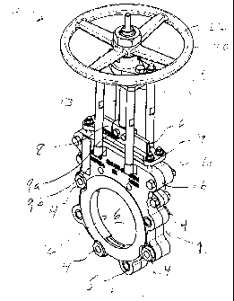
L'invention concerne une vanne à guillotine comprenant un corps de vanne défini par un premier et un deuxième demi-corps. Les demi-corps de vanne sont assemblés pour définir un passage d'écoulement, un évidement de guillotine et un évidement de siège. Une guillotine est disposée entre les demi-corps et est prévue pour traverser l'évidement de guillotine. La guillotine est configurée de façon à pouvoir se trouver en position ouverte afin de permettre à un flux de traitement de traverser la vanne et en position fermée pour empêcher le flux de traitement de traverser la vanne. Un ensemble siège est positionné à l'intérieur du guide d'évidement et est défini par un segment horizontal, une paire de segments verticaux et un segment inférieur. L'ensemble siège est comprimé entre le premier et le deuxième demi-corps de vanne. Au moins une plaque de renfort est disposée à l'intérieur d'une partie du segment horizontal, de telle sorte que le segment horizontal conserve sa rigidité lorsque la guillotine traverse l'ensemble siège.


Abrégé anglais


A knife gate valve
includes a valve body defined by
a first and second body halves. The
valve halves are assembled to define
a flow path, a knife gate channel
and a seat channel. A knife gate is
disposed between the body halves
and is adapted to traverse the gate
channel. The knife gate is configured
to be in an open position to allow
process flow through the valve and
a closed position to prevent process
flow through the valve. A seat
assembly is positioned within the
channel guide and is defined by a
horizontal segment, a pair of vertical
segments and a lower segment.
The seat assembly is compressed
between the first and second valve
body halves. At least one reinforcing
plate is disposed within a portion
of the horizontal segment, such that
the horizontal segment maintains its
rigidity when the knife gate traverses
the seat assembly.

Revendications

Note : Les revendications sont présentées dans la langue officielle dans laquelle elles ont été soumises.


What is claimed is:
1. A knife gate valve:
a valve body defining a flow path, a knife gate channel and a seat channel;
a knife gate adapted to traverse said gate channel, said knife gate having a
lower
edge and configured to be in an open position to allow process flow through
said valve and a
closed position to prevent process flow through said valve;
a seat assembly positioned within said channel guide, said seat assembly
defined
by a horizontal segment, a pair of vertical segments and a lower segment
corresponding to said
lower edge of said knife gate, said seat assembly compressed between said
first and second valve
body halves; and
at least one reinforcing plate disposed within a portion of said horizontal
segment,
such that said horizontal segment maintains its rigidity when said knife gate
traverses said seat
assembly.
2. The valve of claim 1 further comprising a first and second body halves
assembled to
define said flow channel, said gate channel and said seat channel, each of
said first and second
body halves having an overhang portion disposed around a portion of said flow
path and
configured to retain said seat assembly within said channel seat.
3. The valve of claim 2 wherein said first body half further includes a flange
portion
extending from said channel seat.
4. The valve of claim 3 wherein said lower segment of said seat assembly
further comprises
a cavity adapted to receive said flange portion of said first body half.
9

5. The valve of claim 2 wherein said second body half further includes a
flange portion
extending from said channel seat.
6. The valve of claim 5 wherein said lower segment of said seat assembly
further comprises
a cavity adapted to receive said flange portion of said second body half.
7. The valve of claim 2 wherein said first body half further includes a
plurality of apertures
in spaced relationship around said first body half and configured to receive
fasteners for
connection with said second body half.
8. The valve of claim 2 wherein said second body half further includes a
plurality of
apertures in spaced relationship around said second body half and configured
to receive fasteners
for connection with said second body half.
9. The valve of claim 1 further comprising a stem assembly connected at a
first end to said
knife gate and at a second end to an actuator such that said actuator raises
and lowers said knife
act.
10. The valve of claim 1 wherein said seat assembly is integrally molded from
an elastomeric
material.
11. The valve of claim 1 wherein said horizontal segment of said seat assembly
further
comprises a gate opening defined by a plurality of interior walls, said gate
opening having
dimensions corresponding to dimensions of said knife gate.
12. The valve of claim 1 wherein said seat assembly further comprising at
least one
reinforcing plate integrally formed within said horizontal segment.
10

13. The valve of claim 1 wherein said valve body is a unitary valve body.
14. The valve of claim 13 wherein said at least one reinforcing plate is a
first reinforcing
plate, said seat assembly further comprising a second reinforcing plate
connected to said first
reinforcing plate and extending down at least one of said pair of vertical
segments.
15. The valve of claim 13 wherein said at least one reinforcing plate is a
first reinforcing
plate, said knife gate valve further comprising a second reinforcing plate
connected to said first
reinforcing plate and extending down a first one of said pair of vertical
segments and a third
reinforcing plate connected to said first reinforcing plate and extending down
a second one of
said pair of vertical segments.
16. The valve of claim 14 further comprising a third reinforcing plate
connected to said
second reinforcing plate and formed within said lower segment of said seat
assembly.
17. The valve of claim 16 further comprising a fourth reinforcing plate
connected to said
second and third reinforcing plate, said fourth reinforcing plate formed
within said lower
segment of said seat assembly.
18. The valve of claim 13 wherein said at least one reinforcing plate is a
first reinforcing
plate, said seat assembly further comprising a second reinforcing plate
integrally formed with
said first reinforcing plate and extending down each of said pair of vertical
segments and said
lower segment.
11

Description

Note : Les descriptions sont présentées dans la langue officielle dans laquelle elles ont été soumises.


CA 02705559 2010-05-11
WO 2009/064940 PCT/US2008/083480
A VALVE ASSEMBLY HAVING A REINFORCED VALVE SEAT
Background of the Invention
[0001] The present invention relates generally to the field of flow control
valves and the
construction thereof. More specifically, the present invention relates to the
internal components
of valves including a reinforced elastomer seat that provides a sealing
surface for the valve
components.
[0002] Flow control valves such as, for example, knife gate valves or line
blind valves,
are used to control the flow of process media and can be particularly well
suited for use with
abrasive and corrosive slurries used in, for example, the mining, pulp or
paper industries. One
form of gate valve known in the art includes a housing constructed of two
halves that when
coupled together form the valve housing and passageway therethrough. On
opposite sides of the
housing are connections for installing the valve in a pipe line, for example,
the housing can be
bolted to a flange end of a pipe. To control the flow of fluid through the
valve, the valve
includes a knife gate that is disposed within a valve body which is comprised
of two valve body
halves. In operation, when the knife gate is raised, the valve is open and
process media flows
through the passageway. When the knife gate is lowered, the valve is closed
and process media
is prevented from flowing through the passageway.
[0003] Each of the valve body halves includes a recess in which is disposed a
valve seat
that provides a sealing function between the knife gate and the valve body.
The valve seat seals
against the gate when the gate is in the open configuration to allow for
process media to flow
through the valve while substantially preventing process leakage out of the
valve housing.
1

CA 02705559 2010-05-11
WO 2009/064940 PCT/US2008/083480
Previous valve seats include a top horizontal portion which is displaced
within the valve body
when the gate valve is lowered or raised. This movement with the recesses of
the valve body
causes process media to leak into the valve housing. One previous valve seat
included one or
more injection chambers within the horizontal portion of the valve seat. These
chambers were
accessible from outside the valve housing and adapted to receive injectable
packing which
created a seal with the knife gate. However, use of injectable packing did not
provide a rigid
enough valve seat to prevent displacement within the recesses of the valve
body. Thus, there is a
need for a knife gate valve seat configured to prevent displacement within a
valve housing when
the valve is opened and closed.
Summary of the Invention
[0004] Preferred embodiments of the inventions are directed to a knife gate
valve having
a valve body defined by a first and second body halves. The valve halves are
assembled to
define a flow path, a knife gate channel and a seat channel. A knife gate is
disposed between the
body halves and adapted to traverse the gate channel. The knife gate is
configured to be in an
open position to allow process flow through said valve and a closed position
to prevent process
flow through the valve. The knife gate also includes a lower edge. A seat
assembly is positioned
within the channel guide and is defined by a horizontal segment, a pair of
vertical segments and a
lower segment corresponding to the lower edge of the knife gate. The seat
assembly is
compressed between the first and second valve body halves. At least one
reinforcing plate is
disposed within a portion of the horizontal segment, such that the horizontal
segment maintains
its rigidity when the knife gate traverses the seat assembly.
2

CA 02705559 2010-05-11
WO 2009/064940 PCT/US2008/083480
Brief Description of the Drawings
[0005] FIG. 1 is a perspective view of a knife gate valve having a valve
sleeve in
accordance with the present invention.
[0006] FIG. 2 illustrates a cut-away interior view of a body half of the knife
gate valve
shown in FIG. 1.
[0007] FIG. 3 is a perspective view of seat assembly of the knife gate valve
shown in
FIG. 1.
[0008] FIG. 4 is a cross sectional view of the seat assembly shown in FIG. 3
taken along
lines A-A.
[0009] FIG 5 is a perspective view of another embodiment of a knife gate valve
having a
valve sleeve in accordance with the present invention.
[0010] FIG 6 is a perspective view of unitary valve body of the knife gate
valve shown in
FIG. 5.
[0011] FIG. 7 is a perspective view of the seat assembly of the knife gate
valve shown in
FIG. 5.
[0012] FIG 8 illustrates reinforcing plates which are integrally formed within
the seat
assembly shown in FIG. 7.
Detailed Description
[0013] FIG 1 is a perspective view of an embodiment of a knife gate valve for
connection
within a process line in accordance with the present invention. Valve 10
generally includes body
halves 1 a and 1 b which define a valve housing 1 and a pathway or channel 2
through which
process media flows. Body halves la and lb form a gate channel which receives
gate 6 which
3

CA 02705559 2010-05-11
WO 2009/064940 PCT/US2008/083480
opens to allow process flow through valve 10 and closes to prevent process
flow through valve
10. The body halves la and lb are connected via a plurality of body bolts 4
received by threaded
apertures 5 disposed in spaced relationship around body halves la and lb. Yoke
posts 18 are
connected to body halves la and lb at a first end and to yoke top plate 19 at
a top or second end.
Stem assembly 13 is connected to gate 6 via fastener block 8 which may
include, for example
fasteners 9a and 9b. Handwheel 22 is mounted above top plate 19 and when
turned, rotates
stemnut (not shown) to pull the stem linearly up and down which raises and
lowers gate 6.
Although valve 10 is shown with handwheel actuation, other types of actuators
including, but not
limited to pneumatic, hydraulic and electric may also be employed to open and
close gate 6.
[0014] FIG. 2 illustrates a cut-away interior view of body half 1 a having a
plurality of
orifices 24 adapted to receive body bolts 4. The interior surface 21 of body
half 1 a includes a
recessed channel guide 25 which receives seat assembly 40 (shown in FIG. 3).
Channel guide 25
is comprised of a substantially horizontal channel portion 26, a pair of
substantially vertical
channel portions 27 and a curved channel portion 28. Body half 1 a further
includes a flange
portion 29 located within curved channel portion 28 which assists in the
retention of seat
assembly 40 within housing. Overhang section 30 of the interior of body half 1
a forms a portion
of channel guide 25 as well as sections of vertical channels 27. Overhang
section 30 assists in
the retention of seat assembly 40 within housing 1 as described below. Body
half lb is a mirror
image of body half I a.
[0015] FIG. 3 is a perspective view of seat assembly 30 defined by horizontal
segment
36, a pair of vertical segments 37 and a curved lower segment 38. Seat
assembly 30 is
positioned within channel guide 25 such that a seal is formed between gate 6
and seat 30 when
gate 6 is in a closed position within valve 10. Seat assembly 30 may be
comprised of an
4

CA 02705559 2010-05-11
WO 2009/064940 PCT/US2008/083480
elastomeric material with each of segments 36, 37 and 38 integrally formed.
Conversely, seat
assembly 30 is configured to allow gate 6 to move upward within housing 1 when
valve 10 is in
an open position. A ridge 41 is centrally disposed along the interior surface
40 of vertical
segments 37 and curved lower segment 38 of seat assembly 30. This ridge 41
contacts an outer
perimeter of gate 6 when valve 10 is in a closed position. Curved segment 38
includes a cavity
42 which receives flange portion 29 (shown in FIG. 2) of body half I a.
Similarly, the opposite
side of curved segment 38 also includes a second cavity which receives a
flange portion of body
half lb. Horizontal segment 36 includes a gate opening 43 defined by interior
walls 36a, 36b,
36c and 36d through which gate 6 is positioned. Gate opening 43 has length and
width
dimensions corresponding to the length and width dimensions of gate 6 such
that when gate 6 is
in a closed position, the interior walls 36a, 36b, 36c and 36d of horizontal
segment 36 form a
sufficient seal with the perimeter surface of gate 6.
[0016] FIG. 4 is a cross sectional view of seat assembly 30 taken along lines
A-A.
Horizontal segment 36 includes a reinforcing plate 45 which is integrally
formed with the
elastomer material and positioned on each side of gate opening 43. Reinforcing
plate 45 includes
an opening or slot which is aligned with gate opening 43. Reinforcing plate 45
may be, for
example, made from metal and may run the entire length of horizontal segment
36 or a portion of
the length of horizontal segment 36. Reinforcing plate 45 provides rigidity to
seat assembly 30
and in particular horizontal segment 36 to maintain its structure as gate 6
traverses through
opening 43 when valve 10 is opened and closed. In this manner, displacement of
seat assembly
30 within recessed channel guide 25 is reduced thereby alleviating possible
leaks within the
valve housing 1 when knife gate 6 is opened and closed. In addition,
reinforcing plate 45
prevents opening 43 and associated interior walls 36a, 36b, 36c and 36d from
expanding when in

CA 02705559 2010-05-11
WO 2009/064940 PCT/US2008/083480
contact with the perimeter surface of gate 6. Returning briefly to FIG. 2,
once horizontal
segment 36 is positioned within horizontal channel portion 26, packing
material is filled on top
of segment 36 and packing gland 7 is attached to body halves 1 a and lb.
Packing materials used
are those well known in the art and may include, for example, various yams
such as acrylic,
Teflon , Teflon graphite, Kevlar , etc. These materials may be braided into a
square packing
material, a modable material composed primarily of Teflon or a packing braided
around an
elastomer core.
[0017] FIG 5 is a perspective view of another embodiment of a knife gate valve
for
connection within a process line in accordance with the present invention
having a unitary valve
body 101. In particular, valve 100 generally includes a unitary valve body 101
which defines a
pathway or channel 102 through which process media flows. Unitary valve body
101 includes a
gate channel that receives gate 106 which opens to allow process flow through
valve 100 and
closes to prevent process flow through valve 100. Unitary valve body 101 is
connected to a
process pipeline via a plurality of threaded apertures 105 disposed in spaced
relationship around
unitary body 101. Yoke posts 118 are connected to unitary body 101 at a first
end and to yoke
top plate 119 at a top or second end. Stem assembly 113 is connected to gate
106 via fastener
block 108 which may include, for example fasteners 109a and 109b. Handwheel
122 is mounted
above top plate 119 and when turned, rotates stemnut (not shown) to raise and
lower gate 106.
Again, although valve 100 is shown with handwheel actuation, other types of
actuators
including, but not limited to pneumatic, hydraulic and electric may also be
employed to open and
close gate 106.
[0018] FIG 6 is a perspective view of unitary valve body 101 defining a
pathway or
channel 102 through which process media flows. Unitary valve body 101 includes
a seat channel
6

CA 02705559 2010-05-11
WO 2009/064940 PCT/US2008/083480
126 similar to the channel formed by body halves la and lb shown in FIGS. 1
and 2. Valve seat
assembly 130 shown in FIG. 7 is positioned in seat channel 126 of unitary body
101 such that a
seal is formed between gate 106 and seat 130 when gate 106 is in a closed
position within valve
100. In particular, FIG. 7 is a perspective view of seat assembly 130 defined
by horizontal
segment 136, a pair of vertical segments 137 and a curved lower segment 138.
Seat assembly 30
may be comprised of an elastomeric material with each of segments 136, 137 and
138 integrally
formed. Gate opening 143 has length and width dimensions corresponding to the
length and
width dimensions of gate 106 such that when gate 106 is in a closed position,
the interior walls
of opening 143 of horizontal segment 36 forms a sufficient seal with the
perimeter surface of
gate 106. In addition, ridge 141 is centrally disposed along the interior
surface 140 of vertical
segments 137 and curved lower segment 138 of seat assembly 130. This ridge 141
contacts the
outer perimeter of gate 106 when valve 100 is in a closed position.
[0019] Because seat assembly 130 is positioned in unitary valve body 101
rather then
between 2 valve body halves, sufficient rigidity is needed to force the seat
into seat channel 126.
FIG 8 illustrates reinforcing plates 136a, 137a, 137b, and 138a which are
integrally formed
within each of the seat assembly segments 136, 137 and 138. The reinforcing
plate positioned
within segment 136 includes an opening or slot 150 which is aligned with gate
opening 143.
Reinforcing plates 136a, 137a, 137b, and 138a may be a single piece of metal
or other
sufficiently rigid material to allow seat assembly 130 to maintain its
structure when installed in
seat channel 126 of valve body 101. The elastomer material used to form the
seat assembly is
then molded around the reinforcing plates 136a, 137a, 137b, and 138a. Once
installed in the seat
channel, packing material is placed on top of the seat assembly 130 together
with a packing
gland 107 (shown in FIG. 5) to retain the seat assembly within valve body 101.
7

CA 02705559 2010-05-11
WO 2009/064940 PCT/US2008/083480
[0020] While the present invention has been disclosed with reference to
certain
embodiments, numerous modifications, alterations and changes to the described
embodiments
are possible without departing from the sphere and scope of the present
invention, as defined in
the appended claims. Accordingly, it is intended that the present invention
not be limited to the
described embodiments, but that it has the full scope defined by the language
of the following
claims, and equivalents thereof.
8

Dessin représentatif
Une figure unique qui représente un dessin illustrant l'invention.
États administratifs

2024-08-01 : Dans le cadre de la transition vers les Brevets de nouvelle génération (BNG), la base de données sur les brevets canadiens (BDBC) contient désormais un Historique d'événement plus détaillé, qui reproduit le Journal des événements de notre nouvelle solution interne.

Veuillez noter que les événements débutant par « Inactive : » se réfèrent à des événements qui ne sont plus utilisés dans notre nouvelle solution interne.

Pour une meilleure compréhension de l'état de la demande ou brevet qui figure sur cette page, la rubrique Mise en garde , et les descriptions de Brevet , Historique d'événement , Taxes périodiques et Historique des paiements devraient être consultées.

Historique d'événement

Description Date
Inactive : Morte - Taxe finale impayée 2017-02-17
Demande non rétablie avant l'échéance 2017-02-17
Réputée abandonnée - omission de répondre à un avis sur les taxes pour le maintien en état 2016-11-14
Réputée abandonnée - les conditions pour l'octroi - jugée non conforme 2016-02-17
Un avis d'acceptation est envoyé 2015-08-17
Lettre envoyée 2015-08-17
Un avis d'acceptation est envoyé 2015-08-17
Inactive : Q2 réussi 2015-06-12
Inactive : Approuvée aux fins d'acceptation (AFA) 2015-06-12
Modification reçue - modification volontaire 2015-04-23
Inactive : Dem. de l'examinateur par.30(2) Règles 2014-10-29
Inactive : Rapport - Aucun CQ 2014-10-23
Lettre envoyée 2013-11-25
Requête d'examen reçue 2013-11-13
Inactive : Transfert individuel 2013-11-13
Toutes les exigences pour l'examen - jugée conforme 2013-11-13
Exigences pour une requête d'examen - jugée conforme 2013-11-13
Inactive : Page couverture publiée 2012-06-08
Inactive : Notice - Entrée phase nat. - Pas de RE 2011-05-18
Exigences relatives à une correction du demandeur - jugée conforme 2011-05-18
Inactive : Acc. réc. de correct. à entrée ph nat. 2010-11-08
Inactive : Notice - Entrée phase nat. - Pas de RE 2010-09-21
Inactive : CIB attribuée 2010-06-30
Inactive : CIB enlevée 2010-06-30
Inactive : CIB en 1re position 2010-06-30
Inactive : CIB attribuée 2010-06-30
Demande reçue - PCT 2010-06-29
Inactive : CIB attribuée 2010-06-29
Inactive : CIB en 1re position 2010-06-29
Exigences pour l'entrée dans la phase nationale - jugée conforme 2010-05-11
Demande publiée (accessible au public) 2009-05-22

Historique d'abandonnement

Date d'abandonnement Raison Date de rétablissement
2016-11-14
2016-02-17

Taxes périodiques

Le dernier paiement a été reçu le 2015-11-10

Avis : Si le paiement en totalité n'a pas été reçu au plus tard à la date indiquée, une taxe supplémentaire peut être imposée, soit une des taxes suivantes :

  • taxe de rétablissement ;
  • taxe pour paiement en souffrance ; ou
  • taxe additionnelle pour le renversement d'une péremption réputée.

Les taxes sur les brevets sont ajustées au 1er janvier de chaque année. Les montants ci-dessus sont les montants actuels s'ils sont reçus au plus tard le 31 décembre de l'année en cours.
Veuillez vous référer à la page web des taxes sur les brevets de l'OPIC pour voir tous les montants actuels des taxes.

Historique des taxes

Type de taxes Anniversaire Échéance Date payée
Taxe nationale de base - générale 2010-05-11
TM (demande, 2e anniv.) - générale 02 2010-11-15 2010-10-21
TM (demande, 3e anniv.) - générale 03 2011-11-14 2011-10-25
TM (demande, 4e anniv.) - générale 04 2012-11-14 2012-10-23
TM (demande, 5e anniv.) - générale 05 2013-11-14 2013-10-21
Enregistrement d'un document 2013-11-13
Requête d'examen - générale 2013-11-13
TM (demande, 6e anniv.) - générale 06 2014-11-14 2014-11-03
TM (demande, 7e anniv.) - générale 07 2015-11-16 2015-11-10
Titulaires au dossier

Les titulaires actuels et antérieures au dossier sont affichés en ordre alphabétique.

Titulaires actuels au dossier
PENTAIR VALVES & CONTROLS US LP
Titulaires antérieures au dossier
DAVID GAMBETTA
DONALD DEVINE
JOHN MURAN
Les propriétaires antérieurs qui ne figurent pas dans la liste des « Propriétaires au dossier » apparaîtront dans d'autres documents au dossier.
Documents

Pour visionner les fichiers sélectionnés, entrer le code reCAPTCHA :


Pour visualiser une image, cliquer sur un lien dans la colonne description du document. Pour télécharger l'image (les images), cliquer l'une ou plusieurs cases à cocher dans la première colonne et ensuite cliquer sur le bouton "Télécharger sélection en format PDF (archive Zip)" ou le bouton "Télécharger sélection (en un fichier PDF fusionné)".

Liste des documents de brevet publiés et non publiés sur la BDBC .

Si vous avez des difficultés à accéder au contenu, veuillez communiquer avec le Centre de services à la clientèle au 1-866-997-1936, ou envoyer un courriel au Centre de service à la clientèle de l'OPIC.


Description du
Document 
Date
(aaaa-mm-jj) 
Nombre de pages   Taille de l'image (Ko) 
Abrégé 2010-05-10 2 78
Description 2010-05-10 8 316
Dessins 2010-05-10 6 188
Revendications 2010-05-10 3 102
Dessin représentatif 2010-09-21 1 29
Revendications 2015-04-22 4 141
Rappel de taxe de maintien due 2010-07-14 1 114
Avis d'entree dans la phase nationale 2010-09-20 1 195
Avis d'entree dans la phase nationale 2011-05-17 1 196
Rappel - requête d'examen 2013-07-15 1 117
Accusé de réception de la requête d'examen 2013-11-24 1 176
Courtoisie - Certificat d'enregistrement (document(s) connexe(s)) 2013-11-24 1 102
Avis du commissaire - Demande jugée acceptable 2015-08-16 1 161
Courtoisie - Lettre d'abandon (AA) 2016-03-29 1 163
Courtoisie - Lettre d'abandon (taxe de maintien en état) 2016-12-27 1 172
PCT 2010-05-10 1 50
Correspondance 2010-11-07 5 127