Note : Les descriptions sont présentées dans la langue officielle dans laquelle elles ont été soumises.
CA 02706067 2010-05-28
09HR 230245
CAPACITIVE PROXIMITY DETECTION SYSTEM FOR AN APPLIANCE
BACKGROUND OF THE INVENTION
The present invention relates generally to proximity detection systems, and
more particularly to a capacitive proximity detection system for an appliance
such as a refrigerator.
Capacitive proximity sensors and systems rely on electrostatic fields that are
disturbed. When an object passes the sensing face of the capacitive
proximity sensor, the electric field is disturbed and provides an output
signal.
Physical contact with the object is not required and any type of object can be
detected, without regard to material or conductivity.
Although devices employing capacitive proximity sensors are known, the
application of capacitive proximity sensors in refrigerators is problematic
because the refrigerator is typically a large, grounded metal object. The
large
size of refrigerators, and the corresponding ground plane affects capacitive
proximity detection since the ground plane absorbs the electrostatic field.
This diminishes the range of proximity detection systems in refrigerators. It
would be advantageous to be able to reduce the influence of the ground plane
of a refrigerator in a proximity detection system for an appliance. It would
also
be advantageous to enhance the range of proximity sensing in a refrigerator.
BRIEF DESCRIPTION OF THE INVENTION
As described herein, the exemplary embodiments overcome one or more of
the above or other disadvantages known in the art.
One aspect of the exemplary embodiments relates to a proximity detection
system for an appliance. The system includes an electrically conductive
sensor for a capacitive proximity detection system, the sensor being a part of
- 1 -
CA 02706067 2010-05-28
09HR 230245
an accessory device for the appliance; and an electrically conductive member
disposed substantially behind and opposite a location of the sensor and
electrically connected to a ground potential to form a ground shield for the
sensor.
Another aspect of the exemplary embodiments relates to an appliance. The
appliance includes a chassis; a capacitive proximity detection system
supported by the chassis, the capacitive proximity detection system
comprising an electrode for generating a electrostatic field; and an
electrically
conductive member supported by the chassis and disposed substantially
opposite from a location of the electrode, the electrically conductive member
being electrically connected to a ground potential to form a ground shield for
the electrode.
Still another aspect of the exemplary embodiments relates to a refrigerator.
The refrigerator includes a chassis; an accessory device supported by the
chassis, the accessory device comprises an electrically conductive part which
forms an electrode of a capacitive proximity detection system for generating a
electrostatic field; and an electrically conductive member supported by the
chassis and at least partially surrounding the electrode, the electrically
conductive member being electrically connected to a ground potential to form
a ground shield for the electrode.
These and other aspects and advantages of the exemplary embodiments will
become apparent from the following detailed description considered in
conjunction with the accompanying drawings. It is to be understood, however,
that the drawings are designed solely for purposes of illustration and not as
a
definition of the limits of the invention, for which reference should be made
to
the appended claims. Moreover, the drawings are not necessarily drawn to
scale and unless otherwise indicated, are merely intended to conceptually
illustrate the structures and procedures described herein. In addition, any
suitable size, shape or type of elements or materials could be used.
- 2 -
CA 02706067 2010-05-28
09HR 230245
BRIEF DESCRIPTION OF THE DRAWINGS
In the drawings:
Fig. 1 is a schematic illustration of an exemplary appliance incorporating
features of an exemplary embodiment;
Fig. 2 is a schematic illustration of accessory housing for an appliance
incorporating features of an exemplary embodiment;
Fig. 3 is a schematic illustration of a capacitive proximity detection system
incorporating features of an exemplary embodiment.
DETAILED DESCRIPTION OF THE EXEMPLARY EMBODIMENTS OF THE
INVENTION
Referring to FIG. 1, one embodiment of an appliance 100 incorporating a
proximity detection system of the present invention is illustrated. In the
exemplary embodiments described herein, the appliance 100 will be referred
to as a refrigerator. However, the aspects of the disclosed embodiments are
not so limited, and the appliance 100 can include any suitable appliance that
incorporates range and proximity detection functions and devices, such as for
example a range, a washer/dryer or other similar appliance.
The aspects of the disclosed embodiments address the need for short-range
proximity detection capability (approximately 1 foot) for the appliance 100.
Capacitive proximity detection depends on electrostatic fields that are
disturbed for sensing. When the appliance 100 has a large electrically
conducting chassis or body 102, capacitive proximity detection can be
negatively affected. The aspects of the disclosed embodiments utilize an
electrically conductive portion of the appliance 100 as the capacitive sensor
for the capacitive proximity detection system and a ground shield behind the
electrically conductive portion to minimize the influence of appliance body
102
on the capacitive sensor and therefore extend the range of proximity sensing.
- 3 -
CA 02706067 2010-05-28
09HR 230245
As shown in FIG. 1, the appliance 100 has the chassis or body 102 that
includes a left door 104, right door 106, each having a front surface 108 and
110, respectively. In alternate embodiments, the appliance 100 can have a
single door, or more than two doors. In one embodiment the chassis 102 is
formed from an electrically conductive material, such as for example,
stainless
steel. In alternate embodiments, the chassis 102 of the appliance 100 can be
formed from any suitable material.
In one embodiment, an accessory device 112 is shown mounted in one of the
doors, in this example, door 104. As shown in FIG. 1, the accessory device
112 can be integral to the front surface 108 of door 104. In alternate
embodiments, the accessory device 112 can be located in any suitable area
of the appliance 100. In the example shown in FIG. 1, the accessory device
112 includes a water and/or ice dispenser for a refrigerator. For descriptive
purposes, the aspects of the disclosed embodiments will be described with
reference to a water dispenser for a refrigerator. In alternate embodiments,
the accessory device 112 can include any suitable accessory for an
appliance, other than including a water dispenser. For
example, the
accessory device 112 could comprise an interactive display or control panel
for the refrigerator.
As shown in FIG. 1, the water dispenser 112 includes one or more
components, such as for example control panel 114 and buttons or keys 116.
The dispenser 112 also includes a cup switch 118, a cup recess 120 and a
drip tray 122. In alternate embodiments, the water dispenser 112 can include
any number of components related to the operation of the dispenser 112
and/or refrigerator 100.
Referring to FIG. 2, a rear view of a housing or frame 200 for the exemplary
water dispenser 112 of FIG. 1 is illustrated. The housing 200 is usually made
of electrically insulating material. When installed in an appliance, such as
the
refrigerator 100 of FIG. 1, generally only the front or forward facing portion
202 of the housing 200 is visible to the user. The rear, or inward facing
- 4 -
CA 02706067 2010-05-28
09HR 230245
portion 204 of the housing 200 is maintained in a suitable enclosure or recess
in the door 104 of FIG. 1. More specifically, the rear portion 204 of the
housing 200 will be covered from view by interior components of the
refrigerator 100.
As shown in FIG. 2, in one embodiment, an electrically conductive member
206, such as for example, a foil heater, is affixed to the rear portion 204 of
the
housing 200. For exemplary purposes, the electrically conductive member
206 will be referred to as a foil heater, or sweat foil heater. In alternate
embodiments, any suitable electrically conductive member can be used, such
as for example, thin sheets of flexible foil.
The general functions of the foil heater 206 with respect to the housing 200
are not described herein, and do not limit the scope of the disclosed
embodiments. The foil heater 206 generally includes a foil portion 208 and
wire elements 210. In alternate embodiments, the foil heater 206 includes
other suitable parts or components.
The foil heater 206 is configured to be fastened or secured to the rear
portion
204 of the housing 200. The foil heater 206 can be affixed in any suitable
manner, including for example, using an adhesive. In alternate embodiments,
any suitable mechanism can be used, other than including an adhesive.
In order to provide the proximity detection described herein, the appliance
100
of FIG. 1 also includes a capacitive proximity detection system. The
capacitive proximity detection system depends on electrostatic fields that are
disturbed and generally comprises an electrically conductive sensor area and
an electrical ground plane that forms a capacitor having a capacitance that
varies as a result of proximity. A refrigerator is a large, grounded metal
object, and will affect capacitive proximity detection. The aspects of the
disclosed embodiments create a ground shield behind the dispenser 112 that
surrounds the area of the sensor and that is not electrically connected to the
ground plane of the refrigerator body. This greatly extends the range of
proximity sensing and minimizes the influence of the refrigerator body, the
- 5 -
CA 02706067 2010-05-28
09HR 230245
grounded metal object, on the sensor. Positioning the ground shield behind
the dispenser also expands the possibilities for the type of electrode that
could
be used to create the electrostatic field. In the embodiments disclosed
herein,
an electrically conductive component of the dispenser 112, such as a plated
cup-switch 118, can be used as the electrode or sensor.
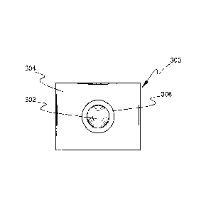
A schematic diagram of an exemplary capacitive proximity system 300 is
shown in FIG. 3. As shown in FIG. 3, the capacitive proximity detection
system 300 generally includes an electrode or sensor 302 and a ground shield
304. The electrode 302 and the ground shield 304 are separated by a
dielectric layer, which in one embodiment comprises air. The capacitive
proximity detection system 300 will include other components related to the
detection of a disturbance in an electrostatic field, as well as the
processing of
that information and the generation of an input signal, that are not necessary
to the understanding of the invention. These other components are known in
the art, and therefore are not described herein.
On or more of the components of the accessory device 112 can include
electrically conductive and non-conductive (non-metal and metallized
components). The components can include an electrically conducting frame
or structure, or an electrically conductive coating. One of the electrically
conductive components of the accessory device 112 is configured to be the
electrode 302 in the capacitive proximity detection system. The aspects of the
disclosed embodiments utilize one of the electrically conductive components
of the accessory device 112 of FIG. 1 as the electrode 302 of FIG. 3 for the
capacitive proximity detection system 300. The foil portion 208 of the foil
heater 206 of FIG. 2, or other similar electrically conductive member, which
is
behind or on the back of the housing 200, is used as the ground shield 304 of
FIG. 3.
For example, in one embodiment, where the accessory device 112 is a water
dispenser, the cup switch 118 is configured to be the electrode 302. In this
example, the cup switch 118, or a portion thereof, is plated with an
electrically
- 6 -
CA 02706067 2010-05-28
09HR 230245
conductive material. The electrically conductive portion of the cup switch 118
is electrically connected to a capacitive proximity detection circuit (not
shown)
in a suitable manner.
If the housing 200 of the water dispenser is electrically conductive, for
purposes of the embodiments described herein, the housing 200 is electrically
isolated from the chassis 102 of the appliance 100 shown in FIG. 1 in any
suitable manner. In one embodiment (not shown) a non-conductive material
or an insulator is configured between the housing 200 and the chassis 102 of
FIG. 1. By electrically isolating the housing 200 from the chassis 102, the
amount of the electrostatic field generated by the electrode 302 of FIG. 3
that
would be shorted to the ground of the chassis 102 is minimized. In such
configuration, there is probably no need to use the foil portion 208 of the
foil
heater 206 as the ground shield 304 for the electrode 302.
In the embodiments disclosed herein, the foil portion 208 of the foil heater
206 shown in FIG. 2 is electrically connected to a ground potential, but is
electrically isolated from the appliance's chassis 102. The ground shield 304
absorbs the electrostatic field that is generated by the electrode 302.
Interruptions in the electrostatic field, such as by a body passing in front
of or
near the electrode 302 will be detected, and provide a corresponding input to
the capacitive proximity detection system. For example, when the refrigerator
100 of FIG. 1 includes a display unit or control panel 114, the control
pane1114
can be configured to activate as the user approaches the refrigerator.
In the embodiments disclosed herein, the ground shield 304 is positioned
substantially behind, or opposite the sensing face of, the sensor 302. As
shown in FIG. 2, the foil heater 206 is positioned on the rear 204 of the
water
dispenser 200 so that the foil heater 206 is substantially opposite an area
212
occupied by the electrically conductive element acting as the electrode 302 of
FIG. 3. In the example described herein, the cup switch 118 is used as the
electrode 302. Thus, the foil heater 206 is positioned so that the foil
portion
- 7 -
CA 02706067 2010-05-28
09HR 230245
208 of the foil heater 206 generally occupies the area 212, which is
substantially behind the cup switch 118 of FIG. 1.
Thus, while there have been shown and described and pointed out
fundamental novel features of the invention as applied to the exemplary
embodiments thereof, it will be understood that various omissions and
substitutions and changes in the form and details of devices illustrated, and
in
their operation, may be made by those skilled in the art without departing
from
the spirit of the invention. For example, in some instances, the appliance
chassis 102 or the combination of the appliance chassis 102 and the foil
heater 26 can be used as a shield for the sensor, depending on the desired
sensing distance. Moreover, it is expressly intended that all combinations of
those elements and/or method steps that perform substantially the same
function in substantially the same way to achieve the same results are within
the scope of the invention. Moreover, it should be recognized that structures
and/or elements and/or method steps shown and/or described in connection
with any disclosed form or embodiment of the invention may be incorporated
in any other disclosed or described or suggested form or embodiment as a
general matter of design choice. It is the intention, therefore, to be limited
only as indicated by the scope of the claims appended hereto.
- 8 -