Note : Les descriptions sont présentées dans la langue officielle dans laquelle elles ont été soumises.
CA 02706979 2015-01-20
1
TITLE OF THE INVENTION
IDENTIFICATION SYSTEM AND METHOD USING HIGHLY COLLIMATED
SOURCE OF ELECTROMAGNETIC RADIATION
CROSS REFERENCE TO RELATED APPLICATIONS
[001] This application claims priority on U.S. Provisional Application No.
60/990,410, filed on November 27, 2007.
FIELD OF THE INVENTION
[002] The present invention relates to an identification system and method
using a highly collimated source of electromagnetic radiation. In particular,
the
present invention relates to a beacon unit, which emits highly directional
radiation towards a thermal imaging unit for secure and/or identification as
friend or foe. The beacon unit may also be used to shield activities,
equipment,
etc., in the vicinity of the beacon unit from the operator of a thermal
imaging
unit.
BACKGROUND OF THE INVENTION
[003] In military applications, secure and covert identification of an asset
as
friend or foe, also referred to as Identification Friend or Foe (IFF) is of
the
utmost importance. Indeed, it is primordial for military platform commanders
to
be able to accurately distinguish friendly aircrafts, vehicles, or forces from
the
enemy in order to prevent accidental fratricide (friendly casualties due to
friendly fire). This becomes increasingly difficult when forces move covertly
through unknown combat zones with limited visibility.
[004] As known in the art, modern technology, and optical 1FF systems in
CA 02706979 2010-05-27
WO 2009/067807
PCT/CA2008/002089
2
particular, ensures that action against friendly forces is reduced or
prevented
by visually identifying potential targets as friend or foe. Typically, optical
IFF
emitters used for such identification operate in the near Infrared (near-IR)
wavelengths, i.e. between 0.7 and 1.3 micrometers (pm), a range very close to
visible light. Although the radiation they emit is invisible to the human eye,
a
major disadvantage of these emitters is that they are highly visible via night
vision systems (NVS), which are commonplace in military applications. NVS
are optical systems, which allow images to be produced in levels of light
approaching total darkness.
[005] Thermal imaging provides an alternative to near-IR systems by enabling
the location of living and inanimate bodies otherwise hidden to be revealed
through their heat signatures. This is done by visualization of the
battlefield with
a thermal imaging device. These devices are sensitive to radiation emitted in
the infrared range of the electro-magnetic spectrum. However, one drawback of
thermal imaging systems is that they typically do not allow to identify and
detect
the bulk of a scene's distinguishable characteristics (i.e. people, places, or
objects). In particular, in military applications, an observer cannot
determine
whether the displayed thermal image represents a "friendly" soldier (i.e. on
their
team) or an enemy as only the heat generated by the soldier is imaged on the
thermal imaging device.
[006] To overcome these and other drawbacks of existing optical IFF systems,
the prior art reveals thermal beacons, which are used for friend or foe
identification through a thermal imager and is otherwise invisible to the
naked
eye and near-IR imaging equipment. Such a beacon typically emits a
continuous series of flashes visible to far-IR imaging equipment when in
operation and is attached to each friendly asset, thus allowing for covert
identification when the beacon is in operation. One drawback of such prior art
thermal beacons, however, is that they typically rely on heating a blackbody
(such as conductive plate or the like) to generate emissions in the infrared
range. As a result, a significant delay is typically experienced between
CA 02706979 2010-05-27
WO 2009/067807
PCT/CA2008/002089
3
successive beacon flashes as the beacon is heated and subsequently cooled
and as a result is typically unsatisfactory for signalling applications
without the
use of a complex shuttering system. Another drawback of such prior art devices
is that blackbody radiation is inherently omnidirectional in nature and as a
result
the distance over which the beacon can be detected by the IR imaging
equipment is limited. Still another disadvantage is that even if the beacon is
proximate enough that it can be detected using the IR imaging equipment, the
image presented to the operator on the display of the equipment as a result of
the radiation emitted by the beacon is small relative to the entire field of
view (in
many cases just a single pixel) and therefore may go undetected by all but the
most vigilant of operators.
SUMMARY OF THE INVENTION
[007] The present invention addresses the above and other drawbacks by
providing an identification system for identifying an asset. The system
comprises an imaging device comprising an array of detectors sensitive to
wavelengths within a predetermined band and a display, and a beacon
positioned in proximity to the asset and at a distance from the imaging
device.
The beacon emits a beam of radiation comprised of wavelengths within the
predetermined band and having a predetermined width at the distance. The
beam is of sufficient strength such that when the beam is incident on the
array,
an image of the beam projected on the display has a relative width which is
greater than the predetermined width.
[008] In accordance with the present invention, there is also provided a
method for identifying an asset in a system comprising an imaging device
comprising an array of detectors sensitive to wavelengths within a
predetermined band and a display, the asset positioned at a distance to the
imaging device. The method comprises positioning a beacon in proximity to the
asset, emitting using the beacon a beam of radiation comprised of wavelengths
within the predetermined band and having a predetermined width at the
CA 02706979 2010-05-27
WO 2009/067807
PCT/CA2008/002089
4
distance, and directing the beam towards the imaging device. The beam is of
sufficient strength such that when the beam is incident on the array, an image
of the beam projected on the display has a relative width which is greater
than
the predetermined width.
[009] Still in accordance with the present invention, there is also provided a
beacon for use in an identification system for identifying an asset, the
system
comprising an imaging device comprising an array of detectors sensitive to
wavelengths within a predetermined band and a display. The beacon
comprises a source of radiation positioned in proximity to the asset and at a
distance from the imaging device and a power supply for operating the source
of radiation. The source of radiation emits a beam of radiation comprised of
wavelengths within the predetermined band and having a predetermined width
at the distance. The beam is of sufficient strength such that when the beam is
incident on the array, an image of the beam projected on the display has a
relative width which is greater than the predetermined width.
BRIEF DESCRIPTION OF THE DRAWINGS
[010] Figure 1 is a schematic diagram of a thermal beacon identification
system in accordance with an illustrative embodiment of the present invention;
[011] Figures 2a and 2b are schematic diagrams of a thermal imaging unit and
an array of sensing elements in accordance with an illustrative embodiment of
the present invention;
[012] Figure 3 is a schematic diagram of a thermal beacon unit in accordance
with an illustrative embodiment of the present invention;
[013] Figure 4 is a schematic diagram of the blooming effect in accordance
with an illustrative embodiment of the present invention; and
CA 02706979 2010-05-27
WO 2009/067807
PCT/CA2008/002089
[014] Figures 5a and 5b are schematic diagrams of sources of radiation in
accordance with alternative illustrative embodiments of the present invention.
DETAILED DESCRIPTION OF THE ILLUSTRATIVE EMBODIMENTS
5
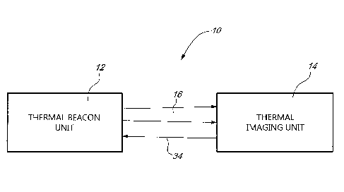
[015] Referring now to Figure 1, a thermal beacon identification system,
generally referred to using the reference numeral 10, will now be described.
The system 10 comprises a thermal beacon unit 12 and a thermal imaging unit
14 positioned at a distance thereto. In operation, the thermal beacon unit 12
emits radiation 16 projected in the direction of the thermal imaging unit 14
for
identification of the thermal beacon unit 12 and associated carrier (soldier,
vehicle, or the like). When detected by the thermal imaging unit 14, an image
of
the radiation 16 is displayed as a spot on the thermal imaging unit 14, thus
eliciting the attention of a viewer observing a scene through it. The system
10
therefore allows for easy visual identification of specific locations, people,
items, targets, and the like through the thermal imaging unit 14.
[016] Referring now to Figures 2a and 2b in addition to Figure 1, the thermal
imaging unit 14 illustratively comprises an array of sensing elements 18, also
referred to as a Focal Plane Array (FPA), consisting of Infrared (IR) detector
elements 20 and electronics implemented on a Read Out Integrated Circuit
(ROIC) 22 for image processing. The ROIC 22 typically serves as a substrate
with the array of IR detector elements 20 being typically bonded thereon in
order to create the FPA, as shown in Figure 2b. The thermal imaging unit 14
further includes conventional optics (i.e. lenses, mirrors, and the like) as
in 24
for shaping and focusing incoming IR radiation as in 16 emitted by a given
object in a scene (in this case the thermal beacon unit 12) and a display 26
for
displaying an image of the detected object.
[017] Typically, thermal imaging units as in 14 detect radiation in the IR
range
and convert it into visible light. As known in the art, thermal imaging is
usually
performed in a predetermined band of wavelengths, illustratively the IR
wavelength region of around 8 to 12 micrometers (pm) or 3 to 5 pm (with many
CA 02706979 2010-05-27
WO 2009/067807
PCT/CA2008/002089
6
devices being listed in the 7 to 15 pm or 3 to 7 pm range) so as to reduce the
effects of atmospheric absorption. The 8 to 12 pm band has the advantage that
an object at 25 degrees Celsius emits close to fifty (50) times more radiation
in
this longer wavelength band than at the shorter 3 to 5 pm band. Also, imaging
units which operate in the 3 to 5 pm range are generally more expensive and
necessitate cooling of the device elements (as shorter wavelength waves have
higher energy). Still, imaging units operating in the 3 to 5 pm range have the
advantage of not suffering from sun bloom. The choice to operate in either the
shorter or longer wavelength band is therefore dependant on the intended
application. In one embodiment of the present invention, the thermal imaging
unit 14 illustratively operates in the wavelength band from 8 to 12 pm, which
corresponds to the thermal Infrared (thermal-IR) range of IR radiation. In
this
range, sensors can obtain a completely passive picture of the outside world
based on thermal emissions only without the need for any external light.
[018] Still referring to Figures 2a and 2b in addition to Figure 1, in
operation,
the radiation 16 focused by optics 24 is first scanned by the array of IR
detector
elements 20, which may be linear, i.e. comprise a single row or column of IR
detector elements 20, or two-dimensional, i.e. consist of a matrix of columns
and rows of IR detector elements 20. The temperature rise in the material of
an
IR detector element 20 caused by the absorption of electromagnetic radiation
as in 16 results in a change in some measurable property (e.g. electrical
charge, voltage, or resistance) of the detector material. For this purpose, a
variety of IR detectors 20 such as resistive bolometers, in which a change in
temperature results in a change in resistance, may be used. A detailed
temperature pattern or thermogram is then created and translated into electric
impulses, which are sent to the ROIC 22 for signal processing (e.g.
amplification, multiplexing...) in order to generate data for display. Each IR
detector element 20 usually corresponds to one pixel of the display 26 of the
thermal imaging unit 14, on which displayed data may appear as grayscale or
different colours depending on the intensity of the IR emission 16. As known
in
the art and as is the case with any camera system, in most cases, the
CA 02706979 2010-05-27
WO 2009/067807
PCT/CA2008/002089
7
impinging radiation 16 will fill the optical device (e.g. lens, system of
lenses,
optical train) as in 24 used to focus the radiation onto the imager array but
will
be shown only on a few pixels of the display 26. In embodiments of the present
invention where data is being sent on the beam 16, there might be only one IR
detector element 20 onto which the optics 24 would focus all radiation 16.
[019] IR detectors as in 20 are generally classified into quantum and thermal
types. To improve detector performance, and thus ensure accurate
measurement, as well as keep the detector element at constant temperature, it
is generally desirable for the quantum detectors generally to be cooled. As
known in the art, various cooling techniques are currently available such as
cryogenic cooling using liquid nitrogen or dry ice, thermoelectric cooling,
Joule-
Thomson cooling, and gas-circulation cooling. Because detector elements are
typically sealed inside a container that cools them below 0 C (or 32 F), the
use
of quantum IR detectors provides for good resolution and sensitivity. Quantum
detectors thus offer high detection performance as well as fast response
speeds. However, their photosensitivity is dependent on wavelength and
quantum detectors are expensive and susceptible to damage from rugged use.
Today, the elements of most IR detectors 20 are thermal detectors, which use
the IR energy as heat and whose photosensitivity is independent of
wavelength. They typically include sensors, which detect photons at a
particular
wavelength and generate an electrical charge, voltage, or resistance, in
relation
to the number of photons detected. Thermal detectors do not require cooling,
i.e. they operate at (or close to) ambient temperature without the need for
artificial means to decrease the temperature if the IR array.
[020] Referring now to Figure 3 in addition to Figure 1, the thermal beacon
unit
12 illustratively comprises a source of radiation 28 operated by a power
supply
30. The thermal beacon unit 12 may further illustratively comprise
conventional
optics as in 32 used to steer the beam 16 into a desired shape, as will be
discussed herein below. The source of radiation 28 is selected to emit
electromagnetic energy in the desired wavelength range, illustratively 8 to 12
CA 02706979 2010-05-27
WO 2009/067807
PCT/CA2008/002089
8
pm, in a highly directional or collimated (i.e. rays substantially parallel)
manner.
As a result, the thermal beacon unit 12 is highly visible at short and long
distances along a narrow emission trajectory via thermal imaging units as in
14,
as will de discussed in further detail below, while being undetectable at any
reasonable distance by common night vision equipment. Before reaching the
thermal imaging unit 14, the radiation 16 emitted by the source of radiation
28
is optionally shaped into a variety of geometries via optics 32 to meet
specific
needs of given applications, as will be explained in further detail herein
below.
[021] Referring now to Figure 4 in addition to Figures 2a and 3, a
phenomenon referred to as blooming may occur when an IR detector as in 20
(and thus the corresponding pixel on the display 26) is saturated with bright
radiation. In this case, the maximum amount of charge that can be
accumulated in an individual pixel, defined by the pixel's full well capacity,
is
reached. As known in the art, the charge capacity of a detector 20 can either
be
limited by the individual pixel characteristics or the detector itself, and is
defined
by the maximum amount of charge that the detector 20 can collect and transfer
while still maintaining all of its design performance specifications. When
this
limit is reached, the pixel or detector 20 is described as being saturated and
accumulation of additional charge generated by incoming photons results in
overflow of the excess electrons into adjacent device structures. The
direction
of electron flow typically depends on the construction of the detector element
20 and usually happens on one axis x or y. Still, as known in the art, for
some
IR detectors 20 (e.g. bolometers or pyroelectric detectors), blooming may not
be due to charge well overflow, as discussed herein above. Instead, blooming
may be related to the specific design and control characteristics of the IR
detector 20 or even to thermal bleed, which is evident when a signal from any
source reaches a pixel on the array and the thermal energy generated at that
pixel moves into neighbouring pixels having a lower temperature.
[022] Still referring to Figure 4 in addition to Figures 2a and 3, blooming is
typically perceived as having a number of potentially undesirable effects
CA 02706979 2010-05-27
WO 2009/067807
PCT/CA2008/002089
9
reflected in the output of the thermal imaging unit 14 (i.e. the captured
images).
These effects often range from image streaks and erroneous pixel signal
values to complete breakdown at the output amplification stage, producing a
dark image. However, in the preferred embodiment of the present invention,
blooming is fostered to advantageously ease visual identification of the
thermal
beacon unit 12, which becomes highly visible through thermal imaging units as
in 14 over both short and long distances. For this purpose, and as discussed
further herein below, the thermal beacon unit 12 uses a highly collimated
source of radiation 28, which has very high power density at great distances.
As a result a relatively great amount of power is delivered to the thermal
imaging unit 14, and such amount of power is sufficient to result in
saturation of
the IR detectors 20 and high charge overflow between adjacent pixels of the
display 26. Blooming of the entire pixel array therefore occurs leading to the
beam 16 appearing on the display 26 as a diffused bright generally circular
patch of light 36 instead of the typical small bright spot 38 expected from a
highly directional beam 16. Indeed, the image of the beam 16 projected on the
display 26 positioned at a given distance from the thermal beacon unit 12 will
have a relative width, which is greater than the width of the beam 16 at that
distance. Detection of the radiation emitted from the thermal beacon unit 12
by
an operator observing the scene through the thermal imaging unit 14 is
therefore aided, thus allowing for more efficient Identification Friend or Foe
(IFF). The degree of blooming could further be adjusted as desired by varying
the amount of power incident on the array 18. Illustratively, the thermal
beacon
unit 12 may comprise a power up and down mode or an attenuator (not
shown), which would allow the user to increase or decrease the power output
of the source of radiation 28, thereby increasing or decreasing the degree of
blooming accordingly. The thermal beacon unit 12 could also be programmable
as an additional feature.
[023] Still referring to Figure 4 in addition to Figures 2a and 3, in other
embodiments of the present invention, blooming is not fostered but detection
is
simply aided due to the fact that the emitted radiation 16 is highly
collimated
CA 02706979 2010-05-27
WO 2009/067807
PCT/CA2008/002089
with very high power density, and thus brighter than conventional thermal
sources at a given distance. As a result, the spot of light 38, which appears
on
the display 26 is brighter than would be the case for other conventional
thermal
beacon units as in 12. In this case, imaging software (not shown) may
5 illustratively be used to further enhance the visibility of the spot of
light 38. For
example, circles, arrows, and the like may be imaged on the display 26 near or
around the displayed spot of light 38, which then becomes even more readily
detectable.
10 [024] Referring now to Figure 5a in addition to Figure 3, the source of
radiation
28 may be one of a plurality of lighting devices including laser devices such
as
gas, liquid or chemical lasers, quantum cascade lasers, direct diode or diode
pumped solid state (DPSS) lasers, other solid state lasers, and optical
parametric oscillator sources. As known in the art, lasers emit radiation in a
narrow, low-divergence beam with a well-defined wavelength, divergence being
the increase in beam diameter with distance from the aperture from which the
beam emerges. They consist of an active medium 40 with appropriate optical
properties inside an optical cavity 42, with a means to supply energy to (i.e.
excite) the active medium 40 in order to produce radiation. In addition to the
known advantages of lasers (e.g. high peak power, directionality, high power
density at great distances due to collimation not achievable with other
radiation
sources), gas lasers in particular have the advantage of containing relatively
inexpensive active material (i.e. gas) and allowing for simplified cooling
mechanisms in comparison to other laser technologies. In addition, RF excited
gas lasers can be built out metal or ceramics instead of glass, as generally
used, in order to improve their ruggedness. Depending on the application, one
of a plurality of gas laser types may be used.
[025] Still referring to Figure 5a in addition to Figure 3, as known in the
art,
carbon dioxide (002) lasers are very high-power lasers. They are also very
efficient with a ratio of output power to exciting power as large as 20%
(illustratively about 5 to 10% in the present application). Typically, they
emit a
CA 02706979 2010-05-27
WO 2009/067807
PCT/CA2008/002089
11
beam of infrared radiation having principal wavelength bands centered around
9.4 and 10.6 pm. Since the 10.6 pm wavelength provides good visibility via
long wave thermal imaging cameras while remaining invisible to detection by
the naked eye or Night Vision Systems (NVS), CO2 lasers provide a good laser
choice for the source of radiation 28 of the present invention. Moreover, as
CO2
lasers typically laser across a couple of dozen lines from about 9 to 11 pm, a
CO2 laser may alternatively be built to illustratively operate at a wavelength
about 9.5 pm with some of the light being subsequently frequency doubled to
generate a wave with a wavelength of 4.75 pm using well understood practices.
In this manner, a single laser tube could generate light waves for both the
desired shorter (3 to 5 pm) and longer (8 to 12 pm) wavelength bands. As a
result, significant benefits in terms of cost, size and required power supply
for
the overall system 10 may be achieved by using such a dual wavelength
thermal beacon unit 12 built from a single wavelength CO2 laser.
[026] Still referring to Figure 5a in addition to Figure 3, carbon monoxide
(CO)
lasers provide another type of laser which may be used for emissions visible
for
the 4 to 7 pm thermal camera range. Nitrogen could be used in the IR range as
well since nitrogen lasers are typically cheaper to build and more efficient.
[027] Still referring to Figure 5a in addition to Figure 3, when gas lasers
are
used as the source of radiation 28, the latter may be manufactured as a single
laser device, which emits both 10 pm and 4 or 5 pm radiation simultaneously.
For this purpose, CO and CO2 gases may either be used in the same laser
cavity as in 42 at the same time, or in two separate cavities 42.
Alternatively
and depending on the applications, the source of radiation 28 may comprise
some laser units, which emit only 4 or 5 pm radiation and a separate laser
unit,
which emits at 10 pm.
[028] Still referring to Figure 5a in addition to Figure 3, the source of
radiation
28 may also be implemented as a Quantum Cascade Laser (QCL), a
semiconductor laser that emits in the mid- to far-IR portion of the
CA 02706979 2010-05-27
WO 2009/067807
PCT/CA2008/002089
12
electromagnetic spectrum, i.e. typically above 3 pm. Since QCLs comprise a
periodic series of thin layers of varying material composition, varying
electrical
potential is introduced across the length of the device. By suitable design of
the
layer thicknesses, it is possible to tune the emission wavelength of the QCLs
over a wide range in the same material system. Indeed, unlike other types of
lasers, QCLs can be manufactured to emit at nearly any wavelength from a few
pm (i.e. about 4 pm) to about 100 pm, such a wavelength tunability feature
being very useful for maximizing atmospheric transmission as many infrared
wavelengths in the band of interest are typically absorbed by gases in the
air.
Illustratively, QCLs would be used in the present invention as the source of
radiation 28 for short wavelength range thermal beacon units as in 12 while
CO2 lasers would be used for higher power longer wavelength thermal beacon
units as in 12.
[029] Still referring to Figure 5a in addition to Figure 3, QCLs further have
the
advantage of being typically electrically pumped with small DC voltages and
currents. Moreover, while advantageously providing relatively high electrical
to
optical efficiencies, QCLs are very small and compact compared to gas lasers
and do not comprise any moving parts, breakable components, or gases, thus
proving rugged and highly suitable for military applications. Thus, in another
embodiment of the present invention, two QCLs operating at two different
wavelengths may illustratively be used, or one gas laser cavity and one QCL
alternatively. Also, as will be apparent to a person of skill in the art, it
may be
possible to use a laser-like cavity relying on spontaneous photon emissions
instead of coherent stimulated emissions, which form the basis of lasers.
[030] Still referring to Figure 5a in addition to Figure 3, in another
alternative
embodiment of the present invention, the source of radiation 28 may comprise
Optical Parametric Oscillators (0P0). OPOs are parametric oscillators,
generally consisting of an optical resonator and a nonlinear optical crystal,
that
allow frequency mixing of input laser light waves to generate new harmonically
related output wavelengths. As a result, laser light frequencies, which are
CA 02706979 2010-05-27
WO 2009/067807
PCT/CA2008/002089
13
difficult or impossible to obtain from any laser, may be synthesized from
other
frequencies, thus offering the potential for wavelength tuning with very wide
tuning ranges. For instance, OPOs may be used to double or half the frequency
of light, add two (2) frequencies of light together to create a higher
frequency or
subtract two (2) frequencies of light to create lower frequencies. Such a
process can also be subsequently cascaded more than once to create yet more
frequencies for which a laser cannot be directly built. As use of OPOs
requires
one or more coherent pump sources with high optical intensity, typically laser
light sources such as DPSS or direct diode lasers, the present invention may
illustratively use QCLs as laser light sources for pumping an OPO to tune the
wavelength of the light output by the source of radiation 28. In this manner,
OPOs can be used for thermal beacon units as in 12 operating in the short to
mid wavelength range.
[031] Still referring to Figure 5a in addition to Figure 3, as known in the
art,
certain types of lasers may be subject to collateral radiation, i.e. radiation
other
than that associated with the primary laser beam. Unlike QCLs, gas lasers,
diode and lamp pumped lasers are particularly susceptible to such radiation,
which may take the form of visible and/or near-IR radiation generated in the
laser optical cavity 42. As a result, it becomes desirable to place a filter
at the
laser output in order to remove such unwanted collateral radiation while still
allowing enough radiation to escape at the laser aperture so as to enable
detection of the thermal beacon unit 12 at great distances. For this purpose,
visible and near-IR filter material could be used.
[032] Referring now to Figure 5b in addition to Figure 3, the source of
radiation
28 may further be a gas discharge lamp, which typically sends electrical
discharge through an ionized gas 44. Such lamps use a noble gas such as
argon, neon, krypton, and xenon or a mixture of these. They are also usually
filled with additional materials such as mercury, sodium, and/or metal
halides.
As known in the art, in operation, the gas 44 is retained within a chamber or
tube 46 and ionised using electrodes (not shown). The ionised gas 44 emits
CA 02706979 2010-05-27
WO 2009/067807
PCT/CA2008/002089
14
photons at wavelengths dictated largely by the gas 44 being ionised. In order
to ensure that emissions emitted by the ionised gas 44 fall within a desired
infrared range, a variety of materials can be used as a filtering separator or
window 48 to separate the gas 44 held within the chamber or tube 46 from the
surrounding environment. These materials serve the dual purpose of retaining
the gas 44 within the chamber or tube 46 and filtering out unwanted
wavelengths of radiation that are emitted by the ionised gas 44. For example,
the separator 48 could be fabricated from silicon (operates at 9 pm),
germanium (operates between 2 and 12 pm), sapphire (operates from the UV
range to 5 pm), germanium sapphire, sodium chloride, lead salt, potassium
bromide and potassium chloride (although the latter is a hydroscopic material
which attracts water molecules and therefore care must be taken to shield the
separator from the surrounding environment). Zinc selenide and zinc sulfide
(operates between 600 nm and 20 pm) could be used as well, either alone (if
used for the sole purpose of retaining the gas 44) or in combination with
other
materials (if it is desirable to achieve filtering of the emitted wavelengths,
as
these materials are generally transparent to visible and near-IR radiation). A
CO or CO2 gas discharge lamp could also be manufactured, resulting in a
source of radiation 28 having an IR signature and power similar to CO or CO2
lasers, yet being significantly cheaper. However, it will be apparent to one
of
skill in the art that, unlike with lasers which emit a well collimated beam,
the gas
discharge lamp will likely generate radiation in all directions (also called
isotropic radiation), which could be further collimated by the use of
conventional
optical devices such as lenses and the like.
[033] In order to obtain high concentrations of radiation and high peak power,
thus ensuring that the thermal beacon unit 12 is easily detectable over long
distances, as discussed herein above, it is desirable for the discharge lamp
to
produce regular flashes of radiation (discharge strobe) instead of producing
continuous or quasi-continuous radiation. Indeed, as known in the art, flashes
emanating from strobe sources are typically very intense. Also, as the lamp
may emit radition in various spectral lines, i.e. broadband in nature, a
separator
CA 02706979 2010-05-27
WO 2009/067807
PCT/CA2008/002089
or window or the like illustratively placed in front of the lamp's cavity can
be
doped to filter particular wavelengths of the radiation emitted by the
discharge
strobe in order to tailor to specific applications. The bandwidth of the
emitted
radiation may further be tailored to the desired ranged (e.g. between 3 and 5
5 pm or 8 and 12 pm) by an increase in the pressure of the ionized gas,
resulting
in a decrease in bandwidth.
[034] Referring to Figure 3, the system 10 benefits from the fact that the
radiation 16 is generated in a highly directional manner. Indeed, unlike other
10 common sources of radiation, which isotropic radiation, resulting in the
energy
decreasing as an inverse square of the distance, the source of radiation 28,
preferably either a laser or discharge strobe, emits energy with a very high
radiance value (indicates how much of the power emitted by an emitting or
reflecting source will be received per solid angle of propagation by an
optical
15 system). This high radiance allows the emitted radiation 16 to be highly
collimated and thus have high power density at great distances, as discussed
herein above. Since the power density emitted by the thermal beacon unit 12
does not significantly drop at great distances, it is a very efficient device
for
long-range detection. Indeed, as known in the art, detection by thermal
imaging
devices at any range does not depend on the total power emitted by the source
of radiation as in 28 but rather on the power density at the location of the
thermal imager. Moreover, the thermal beacon unit 12 has the additional
advantage of consuming less power than would be required for detection of an
isotropic radiator by many orders of magnitude at longer distances.
[035] Still referring to Figure 3, the radiation emitted by the thermal beacon
unit 12 may be required to meet the internationally accepted Maximum
Permissible Exposure (MPE) standard, in order to make the beam "eye-safe".
As known in the art, the MPE is the highest power or energy density of a
source of radiation considered safe, i.e. having a negligible probability for
creating a damage to an observer's eye for instance. In order to abide by MPE
requirements at the device's aperture (e.g. 100mW/cm2 for continuous wave
CA 02706979 2010-05-27
WO 2009/067807
PCT/CA2008/002089
16
(CW) emissions), some sources of radiation 28 may be designed with a large
aperture that allows the radiation energy density at long distances to remain
high while the power density is decreased to a lower level for safety, thus
ensuring that the MPE is not exceeded at the aperture. In this case, large
dimensions may be used in one or both x and y axes as well as highly
divergent beams generated using optics as in 32, as will be described in more
detail herein below.
[036] Still referring to Figure 3, the source of radiation 28 is
illustratively
excited through by the power supply 30. The source of radiation 28 may be
battery operated (rechargeable or disposable) for remote or man-carry
operation, or powered from vehicle power or facility power at a military base.
The power supply 30 may further comprise a control unit (not shown)
integrating digital devices such as microprocessors and the like for
controlling
the level of power delivered to the source of radiation 28. When lasers are
used
as the source of radiation 28, either Direct Current (DC) or Radiofrequency
(RF) electrical signals may be used to excite it. As known in the art, when DC
exciting is used, it is desirable for the laser to be manufactured having an
insulated bore whereas, for gas lasers in particular, RF exciting has the
advantage that the laser tube can be made of conductive material, such as
metal, or ceramic instead of glass, thus lowering the costs and increasing
ruggedness. Moreover, unlike DC exciting, RF exciting does not disassociate
gas molecules, and in particular the CO2 molecules. Thus additional time or
gas are not necessary to recombine the molecules and as such, RF excited
lasers can significantly reduce the gas ballast size and overall cost of the
device.
[037] Referring now to Figure 1 in addition to Figure 3, a laser used as the
source of radiation 28 may be built to emit a continuous beam (CW operation),
a single pulse, or a train of short or long pulses (pulsed operation). In the
CW
mode of operation, the output of the laser is relatively consistent with
respect to
time and maintained by a steady power supply as in 30. In the pulsed mode of
CA 02706979 2010-05-27
WO 2009/067807
PCT/CA2008/002089
17
operation however, the output of the laser varies with respect to time.
Pulsing
may be used to increase detection and discrimination visually either by eye or
by automated means. Pulsing can further be used to transfer information or
indicate the serial number of each thermal beacon unit 12, or other data. When
in pulsed mode, the source of radiation 28 may be operated at several times
(typically two (2) to six (6) times) the CW power level, thus maintaining high
peak power levels while reducing the length desirable for the laser tube. In
addition, to meet the MPE safety standards mentioned herein above, the
source of radiation 28 may alternatively be operated in short pulse mode
instead of long pulse or CW.
[038] The duty cycle and frequency of the laser may also be selected as
uniform or changing, or a combination thereof. For instance, low duty cycle
pulsed operation may be used to extend the life of the power supply 30 as well
as lower the cost and complexity of a potentially integrated cooling system
(not
shown). High frequency pulses may be used to decrease or prevent instances
of missing identification due to passing over the observer's location between
pulses. Indeed, the thermal beacon unit 12 is not visible at any significant
distance unless it is pointed directly at the observer's thermal imaging unit
14.
Thus, if the output beam 16 is swept and not held constant and the duty cycle
is low, the observer might miss a pulse of the thermal beacon unit 12.
[039] Referring back to Figure 1, in other embodiments of the present
invention, the thermal beacon unit 12 may be designed to only emit radiation
when interrogated by a signal 34 from the thermal imaging unit 14. For this
purpose, the signal 34 could illustratively be sent via RF or optically, along
with
an encoded password as a security measure. As a result, this would ensure
that a beacon unit as in 16 only divulges the location of its related friendly
asset
(soldier, vehicle, or the like, as will be described herein below) when the
private
password is received rather than all of the time.
[040] Still referring to Figure 1, the first intended use of the system 10 is
CA 02706979 2010-05-27
WO 2009/067807
PCT/CA2008/002089
18
indeed to save the lives of military personnel by reducing fratricide. For
this
purpose, and as discussed herein above, the thermal beacon unit 12 emits
highly collimated radiation that facilitates effortless identification when
using
thermal imaging devices as in 14. The system 10 may be useful in ground-to-
ground applications in particular, where it is desirable for battlefield
soldiers to
positively identify one another, as well as distinguish equipment or people
locations, including cover locations, caches, and the like. In these
applications,
it is commonplace for most ground vehicles and foot soldiers to carry thermal
imaging devices, which are typically designed to be small and handheld.
Installing thermal beacon units as in 12 on all friendly assets within a
requested
target area would therefore prove very useful for IFF applications. Indeed,
the
thermal beacon unit 12 carried by a friendly vehicle or soldier will only be
visible
to friendly observers carrying thermal imaging devices as in 14, on which it
will
appear as a bright diffused spot.
[041] In aircraft-to-ground and aircraft-to-aircraft applications, thermal
imaging
cameras are also often used to equip aircrafts, thus making the system 10
useful for identifying friendly equipment (e.g. landing zones) and people in
these applications. For example, the system 10 could be used to alert the
aircraft of a "friend". In this case, the thermal beacon unit 12 carried by a
given
soldier or aircraft would emit radiation towards the friendly aircraft for
identification, thus avoiding friendly fire in close air support and further
indicating points of interest or temporary landing or drop zones. Other
applications such as personnel or mobile unit identification, safety (no-fire)
zone identification, or sea and coastal rescue operations may also be
considered.
[042] Referring now to Figures 6a and 6b and 7a, 7b, 7c and 7d in addition to
Figure 3, the radiation 16 emitted by the thermal beacon unit 12 can be
tailored
to specific applications. For this purpose, the optics as in 32 may be
designed
to shape and collimate the beam 16, as mentioned briefly herein above. For
lasers in particular, the degree of collimation of the radiation 16 could be
CA 02706979 2010-05-27
WO 2009/067807
PCT/CA2008/002089
19
adjustable. In some uses (e.g. pointing applications), it may be desirable to
generate a beam 16 that diverges from the x axis by a few (e.g. one (1))
degrees only at a given distance, thus substantially projecting a narrow
intense
beam (point) of radiation that can be directed over long distances. In this
case,
it is desirable for the power intensity to be concentrated in this narrow beam
so
that the thermal beacon unit 12 can be accurately detected by the thermal
imaging unit 14, as discussed herein above. In other uses (e.g. flashlight
applications), it may be desirable to generate a wide beam 16 that can cover a
large area and be more readily visible (e.g. by aircrafts). In this case, the
beam
16 could be designed to diverge highly over the x and/or y axes so as to
generate radiation shaped as a half hemisphere for example. For this purpose
and in order to tailor to specific uses of the thermal beacon unit 12, the
collimation of the beam 16 may be adjusted by various conventional methods
known in the art.
[043] Still referring to Figures 6a and 6b in addition to Figure 3, the optics
32
could illustratively comprise a combination of two or more conventional lenses
50 placed in series (e.g. conventional telescope configuration) at the output
of
the source of radiation 28, as shown in Figure 6a. When disposed in this
manner at a proper distance, the radiation thus emitted would be ideally
collimated. To vary the degree of collimation, i.e. increase or decrease the
divergence of the beam 16, the position of the lenses 50 would preferably be
adjustable along the x axis such that the emitted radiation 16 may be adjusted
from ideally collimated to more or less divergent at a given distance from the
output of the thermal beacon unit 12. Alternatively, conventional telescope
designs may also be used to "up-collimate" the emitted beam 16. In this case
and as known in the art, the beam divergence would be lowered and the power
density at the detection location (i.e. the thermal imaging unit 14)
increased.
The beam 16 could also be shaped to diverge reasonably high over both x and
y axes. For example, the beam 16 could be shaped with a divergence of 25 to
30 milliradians, i.e. the beam would illuminate an area of about 25 to 30
meters
on a side at a typical range limit of about 1000 meters. In either case, and
as
CA 02706979 2010-05-27
WO 2009/067807
PCT/CA2008/002089
will be apparent to one skilled in the art, the optics 32 will be positioned
at a
proper distance so as to obtain the desired effect. In particular, according
to the
application and design requirements (e.g. if it is desired to maintain a lower
and
safer laser class), the optics 32 could for example allow for an increase in
5 divergence only.
[044] Still referring to Figures 6a and 6b in addition to Figure 3, the
collimation
of the beam 16 could also be adjusted by directing it towards a sub-reflector
52,
such as a ball bearing having a size of one (1) to three (3) times the
diameter of
10 the beam 16, so that the radiation directed thereon is illustratively
reflected as a
hemisphere. An aspheric reflector 54 is then illustratively placed around the
sub-reflector 52 such that the beam 16 thus shaped is well collimated. As will
be apparent to a person skilled in the art, by varying the position of either
the
sub-reflector 52 or the aspheric reflector 54 along the x axis, the
collimation of
15 the beam 16 may be varied from well collimated (i.e. substantially
parallel rays)
to highly divergent.
[045] Referring now to Figures 7a, 7b, 7c and 7d in addition to Figure 3,
using
various combinations and orientations of fixed positive and negative
spherical,
20 aspheric, cylindrical, irregular or highly custom lenses, and other
optical
devices arranged to tailor to specific needs, the shape of the beam 16 could
be
further adjusted, resulting in a cone (see Figure 7a), or a triangle
collimated in
one axis (x or y) (see Figures 7b and 7c) for example. Holographic optical
elements (HOE lenses) may also be used to shape the beam 16 as well as
reflectors, metallic mirrors, regular and/or unusual and irregular mirrors,
having
spherical, pyramid, or other convex or concave configuration. Moreover, a
device such as a rotating selecting wheel (not shown) or the like with various
lenses, apertures and/or custom HOE lenses or diffractive phase plates
combined with linear sliders or the like, could illustratively be used to
change
the shape of the beam 16. This would lead to relatively simple construction
and
operation. Typically, the choice of the optics 32 will be influenced by the
overall
cost and efficiency of the system 10.
CA 02706979 2010-05-27
WO 2009/067807
PCT/CA2008/002089
21
[046] Still referring to Figures 7a, 7b, 7c and 7d in addition to Figure 3, in
some embodiments, it may be desirable to project a horizontal line upward into
the airspace at the optimum attack or landing approach angle. When viewed
from above, the emitted radiation 16 would be shaped as a triangle with a
source at the thermal beacon unit 12 (see Figure 7c). In this manner, a Visual
Approach Slope Indicator (VASI), which is a system of lights that provides
visual descent guidance information during the approach to a landing strip,
will
have been built. Although traditional VASIs are built with visible light, the
thermal beacon VASI of the present embodiment will have the advantage of
being invisible to all personnel and aircraft not equipped with thermal
imagers,
thus proving very useful in conflict areas.
[047] Where a triangle collimated in one axis (x or y) is generated, the
thermal
beacon unit 12 may further include a moving device (not shown), such as a
rotary motor, magnet, or the like, for imparting linear, reciprocating or
rotary
motion to the beacon's aperture, thus distributing the beam 16 or plane of
radiation (as generated in Figures 7b and 7c) in multiple directions over
time.
As a result of this rotation, a cone-shaped beam (see Figure 7a) or a
substantially hyperbolic-shaped beam (see Figure 7d) may be obtained.
Alternatively, the beam 16 may be dispersed in a plurality of directions
simultaneously without the use of a moving device. Instead, the design may
include a reflector or mirror including a device such as a chromed ball
bearing
or modified ball bearing of appropriate diameter onto which the beam 16 is
directed, as discussed herein above in reference to Figure 6b. Also, spinning
mirrors, prisms and the like (not shown) could be used to scan the beam 16 at
a high speed. In this case, the device, e.g. a mirror, would illustratively be
spun
(along the x, y axis or other predetermined axis) to generate orbiting of the
beam 16. Acousto-optic (AO) devices such as acousto-optic deflectors (A0Ds)
could also be used to accomplish the same effect in a solid-state manner (for
lasers especially).
CA 02706979 2015-01-20
22
[048] Referring back to Figure 1, in an alternative illustrative embodiment of
the present invention, the thermal beacon unit 12 can be used as a device to
cloak or shield activities what would otherwise be visible to the operator of
a
thermal imaging unit 14. Operation is in principle the same, in that the
source of
radiation 16 is used to drive the IR detector portion (reference 20 in Figure
2a)
of the unit 14 into saturation, thereby resulting in the occurrence of the
blooming effect within the unit 14. As those elements of the IR detector 20
subject to the blooming effect are no longer able to provide any useful
detail,
features which would otherwise have been detectable are effectively masked
by the blooming effect. As a result, the user of a beacon as in 12 could use
the
beacon to shield his activities from the operator of the thermal unit 14.