Note : Les descriptions sont présentées dans la langue officielle dans laquelle elles ont été soumises.
CA 02708621 2012-12-05
MOP WITH WRINGING DEVICE
BACKGROUND OF THE INVENTION
1. Field of Invention
The invention relates to a mop and more particularly to a mop which can be
wrung by repeatedly pressing the handle to rotate together with a mop
receptacle in a
pall.
2. Description of Related Art
A mop is a textile mounted on a handle used for cleaning, e.g., floor
cleaning.
Typically, an individual has to use both hands to wring the wet mop after use.
It is a
laborious job.
Recently, there are many types of so-called automatic mop wringers
commercially available. For example, one type of the mop wringer comprises a
foot
step which in response to be pressed will rotate a mop receptacle in a pail
via a
gear-based actuation mechanism so that a wet mop in the mop receptacle can be
wrung.
However, the person with one foot repeatedly pressing the foot step with great
force and the other foot standing on the floor may slip or fall if sufficient
care is not
taken. Thus, the need for improvement still exists.
SUMMARY OF THE INVENTION
In one aspect, the invention provides a mop comprising an outer tube; an inner
tube telescopically coupled to the outer tube and comprising an intermediate
stop
sleeve and a joint at a lower end, the joint including a receptacle and two
opposite,
spaced bent members with a slot defined therebetween and communicating with
the
receptacle, each bent member having a cam member on an underside of an outer
end;
a strand mount comprising a plurality of strands, a top projection disposed in
the slot
and pivotably secured to the joint, the projection including a top recess, and
a spring
depressible detent anchored in the recess, the
-1 -
CA 02708621 2010-07-09
slot, and the receptacle; a limit sleeve fastened in an upper end of the inner
tube and
comprising a lower toothed section having teeth facing upward; a guide member
slidably disposed in the limit sleeve and comprising a longitudinally
extending spiral
groove, and a plurality of bottom pawls adapted to mesh with the toothed
section in a
ratchet fashion; a spiral member fastened in the outer tube and rotatably
passing
through the spiral groove to rotate the guide member; and a lock assembly
comprising
an inner sleeve including a flared lower portion having a plurality of
longitudinal gaps
spaced therearound, an outer sleeve put on the inner sleeve and including two
opposite upper openings and a flared lower portion, and a U member including a
cam
on bottom of either end, and two pivot pins each driven through one end of the
U
member, the opening, the inner sleeve, and the outer tube to pivotably secure
the U
member, the outer and inner sleeves, and the outer tube together, wherein the
outer
tube is adapted to slide downward until it contacts the stop sleeve; wherein
the U
member is adapted to pivot upward to urge the cams against bottom edges of the
openings so as to move the outer sleeve downward to clamp the lower portion of
the
outer sleeve which in turn clamps the inner tube, thereby locking the lock
assembly;
wherein the U member is adapted to pivot downward to urge the cams against top
edges of the openings so as to move the outer sleeve upward to loosen the
lower
portion of the outer sleeve which in turn loosens the inner tube, thereby
unlocking the
lock assembly; wherein in an upright position of the inner tube, the cam
members are
urged against the strand mount and the recess is urged by the detent with both
the
inner tube and the strand mount being locked; wherein in an oblique position
of the
inner tube, the cam members are not urged against the strand mount and the
recess
is not urged by the detent with both the inner tube and the strand mount
unlocked; and
whereby pivoting the U member downward to slide the inner tube in the outer
tube,
disposing the inner tube in the upright position, and pressing the outer tube
will cause
the guide member to rotate both the inner tube and the strand mount.
-2-
CA 02708621 2012-12-05
2a
According to an aspect of the invention, there is provided a mop comprising:
an outer
tube; an inner tube telescopically coupled to the outer tube and comprising an
intermediate
stop sleeve and a joint at a lower end, the joint including a receptacle and
two opposite,
spaced bent members with a slot defined therebetween and communicating with
the
receptacle, each bent member having a cam member on an underside of an outer
end;
a strand mount comprising a plurality of strands, a top projection disposed in
the slot and
pivotably secured to the joint, the projection including a top recess, and a
spring depressible
detent anchored in the recess, the slot, and the receptacle; a limit sleeve
fastened in an
upper end of the inner tube and comprising a lower toothed section having
teeth facing
upward; a guide member slidably disposed in the limit sleeve and comprising a
longitudinally
extending spiral groove, and a plurality of bottom pawls adapted to mesh with
the toothed
section in a ratchet fashion; a spiral member fastened in the outer tube and
rotatably
passing through the spiral groove to rotate the guide member; and a lock
assembly
comprising an inner sleeve including a flared lower portion having a plurality
of longitudinal
gaps spaced therearound, an outer sleeve put on the inner sleeve and including
two
opposite upper openings and a flared lower portion, and a U member including a
cam on
bottom of either end, and two pivot pins each driven through one end of the U
member, the
opening, the inner sleeve, and the outer tube to pivotably secure the U
member, the outer
and inner sleeves, and the outer tube together, wherein the outer tube is
adapted to slide
downward until it contacts the stop sleeve; wherein the U member is adapted to
pivot
upward to urge the cams against bottom edges of the openings so as to move the
outer
sleeve downward to clamp the lower portion of the outer sleeve which in turn
clamps the
inner tube, thereby locking the lock assembly; wherein the U member is adapted
to pivot
downward to urge the cams against top edges of the openings so as to move the
outer
sleeve upward to loosen the lower portion of the outer sleeve which in turn
loosens the inner
tube, thereby unlocking the lock assembly; wherein in an upright position of
the inner tube,
the cam members are urged against the strand mount and the recess is urged by
the detent
with both the inner tube and the strand mount being locked; wherein in an
oblique position of
the inner tube, the cam members are not urged against the strand mount and the
recess is
not urged by the detent with both the inner tube and the strand mount
unlocked; and
CA 02708621 2012-12-05
2b
whereby pivoting the U member downward to slide the inner tube in the outer
tube,
disposing the inner tube in the upright position, and pressing the outer tube
will cause the
guide member to rotate both the inner tube and the strand mount.
,
CA 02708621 2012-12-05
The above and other features and advantages of the invention will become
apparent from the following detailed description taken with the accompanying
drawings.
BRIEF DESCRIPTION OF THE DRAWINGS
FIG. 1A is a perspective view of a mop according to the invention;
FIG. 18 is a longitudinal sectional view of a portion of the handle above the
stop
sleeve;
FIG. 2 is an exploded view of the mop;
FIG. 3 is an exploded view showing a lower portion of the inner tube to be
assembled with the strand mount;
FIG. 4 is a longitudinal sectional view of the assembled inner tube and strand
mount in FIG. 3;
FIG. 5 is a side elevation of FIG, 4 showing a pivotal operation of the inner
tube;
FIG. 6 is a side elevation of the lock assembly and adjacent portions of the
outer
tube and inner tube in a locked position;
FIG. 7 is a view similar to FIG. 6 showing an unlocked position thereof;
FIG. 8A is a perspective view of the mop disposed in a mop receptacle which is
anchored in a pail in which the mop is wet after use and is ready to be wrung;
FIG. 8B is a longitudinal sectional view of a portion of the handle from the
lock
assembly to its head of FIG. 8A; and
FIG. 8C is a view similar to FIG. 8B showing movements of the components in
FIG.
8B during the wringing.
DETAILED DESCRIPTION OF THE INVENTION
Referring to FIGS. lA to 8C, a mop in accordance with the invention comprises
the following components as discussed in detail below.
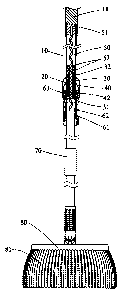
An outer tube 10 has an upper, knurled holding portion 11 and two opposite
lower
through holes 101. An inner tube 20 is telescopically coupled to the outer
tube 10 (i.e.,
- 3 -
CA 02708621 2010-07-09
partially slide into or out of the outer tube 10). A joint 21 is provided at a
lower end of
the inner tube 20. The joint 21 comprises two opposite, spaced about 90-degree
bent
members 211 with a slot 212 defined therebetween, each bent member 211 having
a
cam member 2112 on an underside of an outer end and a through hole 2111 in a
vertical portion proximate the bending point, and a spring depressible detent
213
including a helical spring 2131 disposed in a receptacle 214 in a lower
portion of the
inner tube 20, and a steel ball 2132 engaged with a lower end of the spring
2131.
A limit sleeve 30 is fastened in an upper end of the inner tube 20 and
comprises a
lower toothed section 31 having teeth facing upward, and a fastening ring 32
having
an axial hole 321 fastened in an upper end. A hollow, cylindrical guide member
40
comprises a spiral groove 41 longitudinally extending through a central line,
and a
plurality of pawls 42 formed along a bottom end. The guide member 40 is
slidably
disposed in the limit sleeve 30. That is, an upward movement of the guide
member 40
will be stopped when it contacts the fastening ring 32 and a downward movement
of
the guide member 40 will cause the pawls 42 to mesh with the toothed section
31.
A spiral member 50 comprises a top enlargement 51 fastened in the holding
portion 11 of the outer tube 10. The spiral member 50 passes through the
groove 41
and is adapted to rotate to cause the guide member 40 to rotate too. The pawls
42
mesh with the toothed section 31 (i.e., locked) when the outer tube 10 moves
downward. Thus, the inner tube 20 rotates too. The pawls 42 disengage from the
toothed section 31 (i.e., unlocked) when the outer tube 10 moves upward. Thus,
only
the guide member 40 rotates. Moreover, a plurality of (two) sleeve-like buffer
members 52 are provided with the spiral member 50 passing through. The buffer
members 52 act as pads to smooth upward and downward movements of the spiral
member 50.
A lock assembly 60 comprises an inner sleeve 61 including two opposite upper
through holes 613 and a flared lower portion 611 having a plurality of
longitudinal gaps
-4-
CA 02708621 2010-07-09
612 spaced therearound; an outer sleeve 62 put on the inner sleeve 61 and
including
two opposite upper openings 621 and a flared lower portion 622; and a U member
63
including a cam 632 on bottom of either end, and two pivot pins 631 each
driven
through one end of the U member 63, the opening 621, the through hole 613, and
the
through hole 101 to pivotably secure the U member 63, the outer and inner
sleeves 62,
61, and the outer tube 10 together.
As shown in FIG. 6, the U member 63 is pivoted upward to urge the cams 632
against the bottom edges of the openings 621. As such, the outer sleeve 62
moves
downward to clamp the lower portion 611 which in turn clamps the inner tube
20. As a
result, the outer tube 10 and the inner tube 20 are locked (i.e., the lock
assembly 60 is
locked).
As shown in FIG. 7, the U member 63 is pivoted downward to urge the cams 632
against the top edges of the openings 621. As such, the outer sleeve 62 moves
upward to loosen the lower portion 611 which in turn loosens the inner tube
20. As a
IS result, the
outer tube 10 and the inner tube 20 are unlocked (i.e., the lock assembly 60
is unlocked).
Preferably, the number of the gaps 612 Is four.
A stop sleeve 70 is fixedly provided on an intermediate portion of the inner
tube
20. The outer tube 10 is allowed to slide downward until it contacts the stop
sleeve 70.
A strand mount 80 comprises a plurality of strands 81, a projection 82 on a
top center,
the projection 82 disposed in the slot 212 and including a transverse through
hole 821,
an arcuate top recess 822 with the steel ball 2132 rested thereon, and a pivot
pin 823
driven through the through holes 2111 and 821 to pivotably secure the inner
tube 20
and the strand mount 80 together.
In an upright position of the inner tube 20, the cam members 2112 are urged
against the top of the strand mount 80 and the steel ball 2132 is pushed
downward to
urge against the recess 822 by the spring 2131. As a result, the inner tube 20
is
- 5 -
CA 02708621 2012-12-05
locked (see solid lines of the inner tube 20 of FIG. 5). Also, the strand
mount 80 is
locked (i.e., not rotatable).
In an oblique position of the inner tube 20, the cam members 2112 are not
urged
against the top of the strand mount 80 and the steel ball 2132 is not urged
against the
recess 822 by the spring 2131. As a result, the inner tube 20 is unlocked (see
dash
lines of the inner tube 20 of FIG. 5). This is a use position of the mop with
the strand
mount 80 being rotatable.
A pail 90 comprises a mop receptacle 91 disposed therein. The strand mount 80
can be disposed in the mop receptacle 91.
An individual may use the mop to clean floors after locking the lock assembly
60
and unlocking the inner tube 20 and the strand mount 80 (i.e., the inner tube
20 being
inclined). After use, for wringing the wet strands 81 the individual may put
the strand
mount 80 in the mop receptacle 91. Next, pivot the U member 63 downward to
allow
the inner tube 20 to slide in the outer tube 10. Next, put the inner tube 20
in an upright
position by locking both the inner tube 20 and the strand mount 80. Next,
press and
downward move the outer tube 10. Thus, the guide member 40 rotates due to the
downward spiral movement of the spiral member 50 therethrough. The rotation of
the
guide member 40 causes the inner tube 20 to rotate too because the lock
assembly 6
is unlocked. And in turn, the strand mount 80 rotates. A centrifugal force is
thus
created to squeeze water out of the strands 81. Above steps can be repeated
until the
strands 81 are sufficiently wrung.
- 6 -