Note : Les descriptions sont présentées dans la langue officielle dans laquelle elles ont été soumises.
CA 02709585 2015-07-08
WATER RECOVERY FROM STEAM-ASSISTED PRODUCTION
FIELD OF THE INVENTION
[0003] A method for generating make-up water by recovering water from steam-
assisted
production.
BACKGROUND OF THE INVENTION
[0004] The make-up water supply for future steam-assisted heavy oil
production is an
area of critical concern. There is an ecological push for fresh or "non-
saline" water to not be
used but instead to use saline water, however typically saline water contains
a high amount of
total dissolved solids. The costs associated with treating a water stream with
a high amount
of dissolved solids can be very expensive.
[0005] Water recovery by condensation from commercial-size boiler flue gas
streams is
an idea that has been discussed for quite some time. Many industrial processes
produce
process streams containing condensable components such as water vapor. As the
mere
discarding of these condensable components can constitute a substantial loss
in available heat
energy, it is desirable to recover these condensable components from the
process streams for
economic reasons. It is also desirable to recover the latent heat of
vaporization associated
with such condensable components as a means for reducing process energy
requirements.
The use of heat exchanger-based condensers for the recovery of condensable
components of
process streams and the latent heat of vaporization associated therewith is
well known to
those skilled in the art.
[0006] Methods and apparatuses for the selective removal of one or more
components
from a gaseous mixture are well known. US Patent 4,875,908 teaches a process
for
CA 02709585 2010-07-15
Docket No. 40990
selectively separating water vapor from a multi-component gaseous mixture in
which the
multi-component gaseous mixture comprising the water vapor is passed along and
in contact
with a membrane which is selectively permeable to water vapor. The use of
membranes for
selective removal of one or more components of a gaseous mixture is also
taught by US
Patent 4,583,996 (inorganic porous membrane), US Patent 3,980,605 (fibrous
semi-
permeable membrane) and US Patent 3,735,559 (sulfonated polyxylene oxide
membranes).
[00071 Methods and apparatuses for selective removal of water vapor from a
gaseous
mixture and condensing the separated water vapor to recover its latent heat of
vaporization
are also known. US Patent 5,236,474 teaches a process for removing and
recovering a
condensable vapor from a gas stream by a membrane contactor in which a gas
stream
containing a condensable vapor is circulated on one side of hollow fiber
membranes while
cool extraction fluid is circulated on the other side under a total pressure
differential. As a
result, the condensable vapor in the gas stream is condensed in the gas stream
and the
condensed vapor, i.e. liquid, permeates the membrane and becomes entrained in
the cool
extraction fluid.
[0008] US Patent 4,466,202 teaches a process for recovery and reuse of heat
contained in
the wet exhaust gases emanating from a solids dryer or liquor concentrator by
preferentially
passing the vapor through a semi-permeable membrane, compressing the water or
solvent
vapor, and subsequently condensing the water or soluble vapor in a heat
exchanger, thereby
permitting recovery of its latent heat of vaporization for reuse in the
evaporation process. It
will be apparent to those skilled in the art that a substantial amount of
energy will be required
to compress the water or solvent vapor in accordance with the process of this
patent. US
Patent 5,071,451 teaches a vapor recovery system and process that permits
condenser vent
gas to be recirculated. The system includes a small auxiliary membrane module
or set of
modules installed across a pump and condenser on the downstream side of a main
membrane
unit, which module takes as its feed the vent gas from the condenser and
returns a vapor-
enriched stream upstream of the pump and condenser.
[00091 US Patent 7,066,396 teaches a heating system having a steam
generator or water
heater, at least one economizer, at least one condenser and at least one
oxidant heater
2
CA 02709585 2010-07-15
Docket No. 40990
arranged in a manner so as to reduce the temperature and humidity of the
exhaust gas stream
and recover a major portion of the associated sensible and latent heat. The
recovered heat is
returned to the steam generator or water heater so as to increase the quantity
of steam
generated or water heated per quantity of fuel consumed. In addition, a
portion of the water
vapor produced by combustion of fuel is reclaimed for use as feed water,
thereby reducing
the make up water requirement for the system. However, US Patent 7,066,396
provides no
teaching or suggestion of producing make-up water for a steam-assisted heavy
oil production
system while cleaning and neutralizing the flue gas prior to the heat
recovery.
[0010] US Patent 4,799,941 teaches a method for condensing flue gas in
combustion
plants, and an arrangement of the apparatus. US Patent 4,799,941 attempts to
condense flue
gas in combustion plants by: (a) cooling and humidifying the flue gas by
spraying water
thereinto; (b) cooling and condensing water vapor from the flue gases in a
first condensing
stage, by indirect heat exchange with recirculated water, or return water,
from a hot water
circuit; (c) further cooling and condensing water vapour from the flue gases
in a second
condensing stage, by indirect heat exchange with water from a combustion air
humidifier;
and (d) heating and humidifying combustion air in the humidifier by direct
contact with
heated recirculated water from the second condensing stage. However, US Patent
4,799,941
provides no teaching or suggestion of producing make-up water for a steam-
assisted heavy
oil production system while cleaning and neutralizing the flue gas prior to
the heat recovery.
SUMMARY OF THE INVENTION
[0011] The present embodiment depicts a method of introducing flue gas,
from a flue
stack in a steam-assisted production facility, into a heat exchanger. The flue
gas comprises
boiler combustion products selected from at least one of commercial pipeline
gas and
produced gas. The method begins by cooling a portion of the water vapor in the
flue gas in
the heat exchanger to produce flue gas water. This flue gas water is then
collected and
removed as make-up water.
[0012] The present embodiment also depicts a method which begins by
collecting
production fluids from a steam-assisted heavy oil operation. The production
fluids are then
separated into a produced gas stream, a produced oil stream and a produced
water stream.
3
CA 02709585 2015-07-08
In accordance with one aspect of the present invention, there is provided a
method
comprising: a) introducing flue gas, from a flue stack in a steam-assisted
heavy oil
production facility, into a heat exchanger, wherein the flue gas comprises
boiler
combustion products selected from at least one of commercial pipeline natural
gas and
produced gas; b) cooling the flue gas in the heat exchanger to produce a flue
gas water;
and c) collecting and removing the flue gas water to produce make-up water,
wherein a
neutralizing chemical brings the make-up water produced to a p1-I between 3.0
and 4.5.
In accordance with another aspect of the present invention, there is provided
a method
comprising: a) collecting production fluids from a steam-assisted heavy oil
operation;
b) separating the production fluids into a produced gas stream, a produced oil
stream
and a produced water stream; c) transporting the produced water stream to a
boiler
wherein the produced water stream is converted for use in the steam-assisted
heavy oil
operation; d) transporting the produced gas stream to the boiler, wherein the
produced
gas stream is used as a fuel source; e) cooling the flue gas from the boiler
in a heat
exchanger to condense at least a portion of the water vapor in the flue gas;
and
0 collecting the condensed water vapor and transporting the condensed water
vapor to
a boiler wherein the condensed water vapor is converted to use in the steam-
assisted
heavy oil operation, wherein a neutralizing chemical brings the condensed
water vapor
to a pH between 3.0 and 4.5.
3a
CA 02709585 2010-07-15
Docket No. 40990
The produced water stream is then transported to a boiler wherein the produced
water stream
is converted for use in a steam-assisted heavy oil operation. The produced gas
stream is
transported to the boiler wherein the produced gas stream is used a fuel
source. The flue gas
from the boiler is cooled in a heat exchanger to condense at least a portion
of the water vapor
in the flue gas. The condensed water vapor is then collected and transported
to the boiler
wherein the condensed water vapor is converted to use in the steam assisted
heavy oil
operation.
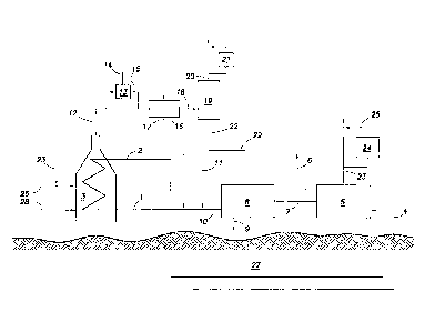
BRIEF DESCRIPTION OF THE DRAWINGS
[0013] The invention, together with further advantages thereof, may best be
understood
by reference to the following description taken in conjunction with the
accompanying
drawings.
[0014] Figure 1 depicts a steam-assisted heavy oil production facility
capable of
recovering make-up water from flue gas.
[0015] Figure 2 depicts the relationship between flue gas temperature and
net water
recovery for a typical commercial steam-assisted heavy oil production
facility.
DETAILED DESCRIPTION OF THE INVENTION
[0016] The present method provides a method of introducing flue gas, from a
boiler flue
stack in a steam-assisted heavy oil production facility, into a heat
exchanger, wherein the
boiler flue gas comprises boiler combustion products selected from at least
one of
commercial pipeline natural gas and produced gas from a steam-assisted heavy
oil production
facility. The first step involves condensing a portion of the water from the
flue gas in the
heat exchanger to produce a flue gas water stream. The flue gas water is then
collected,
removed, adjusted for pH to be compatible with other facility boiler water,
and used as boiler
make-up water.
[0017] Examples of steam-assisted operation methods applicable to this
method include
steam-assisted gravity drainage, steam-assisted heavy oil operation and
cyclical steam
stimulation.
4
CA 02709585 2010-07-15
Docket No. 40990
[0018] The present method has the ability to produce a significant portion
of the water
used in the steam-assisted heavy oil facility as make-up water, such as at
least 10%, 15%,
20%, 25%, 30%, 35%, 40%, 45% or even 50% of that water depending on the water
balance
in the system. Both environmental and financial benefits can be achieved by
recycling the
water used in a steam-assisted heavy oil production facility. It is preferred
that the recovered
water produced from the flue gas is compatible with the make-up water in the
rest of the
facility. This could require pH adjustment to the range of 8-10 pH with
neutralizing
chemicals such as: sodium hydroxide, calcium hydroxide, potassium hydroxide,
ammonia,
ammonium hydroxide, sodium bicarbonate, and sodium carbonate. In alternate
embodiments
the neutralizing chemical would bring the pH to a target range of 3.0 to 7.0
or even between
3.0 and 4.5.
[0019] In one embodiment the heat exchanger is cooled by air forced through
the inside
of tubes where the flue gas is cooled on the outside of the tubes. In another
embodiment the
heat exchanger is cooled by air on forced around the outside of tubes where
the flue gas is
cooled on the inside of the tubes. The temperature of the air expelled by the
heat exchanger
in either embodiment needs to be lower than the water dew point of the flue
gas,
approximately 135 F, and sufficient to cool the flue gas to produce the
desired amount of
recovered water as shown in Figure 2. If ambient air is used for cooling the
heat exchanger,
the size of the heat exchanger needs to be optimized for the amount of make-up
water
needed, so that sufficient water can to be provided to the facility as the
temperature changes
throughout the year.
[0020] In yet another embodiment the heat exchanger is cooled by
circulating a glycol-
water stream, or any other conventional solution that would lower the water
freezing point,
through a tube inside the heat exchanger and the flue gas cooled on the
outside of the tubes.
In this embodiment the glycol-water stream would be cooled externally by
another heat
exchanger such as an air-cooler and recirculated back to the main flue gas
heat exchanger.
The concentration of glycol in this stream can be from 0 to 80 wt%, preferably
40 to 60 wt%
for maximum freeze protection. The glycol-water temperature needs to be lower
than the
water dew point of the flue gas, approximately 135 F, and sufficient to cool
the flue gas to
produce the desired amount of recovered water as shown in Figure 2. If ambient
air is used
CA 02709585 2010-07-15
Docket No. 40990
to cool the glycol-water mixture then the glycol-water temperature will vary
throughout the
year and the equipment sizing of the heat exchangers needs to be optimized for
the amount of
make-up water to be provided to the facility throughout the year.
[0021] The commercial pipeline natural gas and produced gas can be varied
depending
on how much gas is produced in the steam-assisted heavy oil production
reservoir operation.
Mixtures can be 0 to 100 vol% pipeline natural gas and 0 to 100 vol% produced
gas. It is
preferable to burn all the produced gas in order to lower the costs for
purchasing a sufficient
volume of pipeline natural gas to operate the boiler systems. A typical range
of mixtures
consists of 30 to 70 vol% produced gas.
[0022] In one embodiment the boiler flue gas has minimal sulfur content to
reduce the
corrosivity of the recirculating and recovered water. Minimal sulfur content
can be achieved
by any process currently known in the art. In one embodiment minimal sulfur
content is
achieved by chemically treating the flue gas prior to combustion. Examples of
chemicals
that can used to treat the flue gas include but are not limited to chemical
solvents, physical
solvents and solid adsorbents. Representative examples of chemical solvents
include amines
such as monoethanolamine and methyldiethanolamine. Representative examples of
physical
solvents include methanol and dimethyl ethers of polyethylene glycol.
Representative
examples of solid absorbents include zinc oxide.
[0023] The practice of burning produced steam-assisted heavy oil production
reservoir
gas is quite commonly done for economic reasons but can introduce more sulfur
contaminant
into the boiler fuel, which makes the flue gas stream more acidic and
corrosive due to the
presence of sulfur dioxide and sulfur trioxide. Because these latter two
species can also be
absorbed in water and make it corrosive, this makes the condensation of flue
gas vapors from
steam-assisted heavy oil production boilers a unique application not practiced
in the present
art.
[0024] Another type of chemical additive that can be utilized is hydrogen
peroxide.
Hydrogen peroxide can be used to remove sulfur dioxide, nitrogen dioxide and
other
contaminants from flue gas. The use of hydrogen peroxide converts the oxide of
sulfur and
some of the oxide of nitrogen to more stable oxidation states. Acids formed as
a result of this
6
CA 02709585 2010-07-15
Docket No. 40990
conversion, namely sulfuric acid (H2SO4) and nitric acid (HNO3), can then be
neutralized
with base, such as limestone or CaCO3, in an isolated area or enclosure away
from populated
areas. Other known ways to neutralize the acid include using gas
desulfurization techniques
such as wet lime treatment or wet NaHCO3 treatment. Alternatively, depending
on the
demand and purity of the acid products themselves, the sulfuric and nitric
acids can be
collected and processed for sale as an industrial product, enhancing the
economic feasibility
of the present system. The following simplified chemical reactions represent
the processes
involved in both the creation of the contaminants and their removal through
the use of
hydrogen peroxide:
S + 02 4-602
N2+ 024-+2N0
2N0 +02 4- 2NO2
11202+ S024¨>H2SO4
11202+ 2NO2 ¨>211NO3
112SO4 + H20 + CaCO3 ¨> CaSO4=2H20 + CO2
2HNO3 + CaCO3 --* Ca(NO3)2 +1120+ CO2
[0025] By reducing the sulfur species from the natural gas, the corrosivity
of the make-up
water will be reduced. In addition to the methods described above a method can
be
performed using a majority pipeline natural gas for specific steam-assisted
heavy oil
production boilers. This will also reduce the sulfur impurities and reduce the
corrosivity of
the recovered water. A further reduction of sulfur can be achieved by using
natural gas
before it is odorized with sulfur compounds.
[0026] In another embodiment the combusted flue gas is pre-cooled with a
water spray
which is injected directly into the ducting before the heat exchanger to
achieve a temperature
above the dew point of the flue gas, approximately 135 F, but below the
condensation
temperature of sulfur trioxide in flue gas, approximately 210-250 F. In this
embodiment the
7
CA 02709585 2010-07-15
Docket No. 40990
water spray can contain a combusted flue gas neutralizing chemical.
Representative
examples of flue gas neutralizing chemicals include: sodium hydroxide, calcium
hydroxide,
potassium hydroxide, ammonium hydroxide, sodium bicarbonate, and sodium
carbonate.
[0027] In one embodiment the temperature of the temperature of the flue gas
would be
90 F. Although it is possible to still have recovery of water from flue gas
anywhere from
50 F up to 135 F for operability, it is ideal that the temperature of the flue
gas would be
between 80 F to 110 F.
[0028] Figure 1 depicts an embodiment of the present invention for
recovering make-up
water for a steam-assisted heavy oil production facility from its boiler flue
gas. A water
stream 1 is converted to steam 2 in a boiler system 3 which burns at least one
of commercial
pipeline natural gas, 26 and produced gas 23 with air 28. The produced gas 23
which is
detailed further below, can be a combination of cleaned produced gas 25 or
standard
produced gas. The steam 2 is injected underground into a heavy oil or bitumen-
containing
reservoir 27 and a product mixture 4 of bitumen, water and/or gas is collected
and brought to
the surface. This product mixture 4 is sent to a separation facility 5 which
separates the
product mixture 4 into a bitumen 6, a water 7, and produced gas 23. The
bitumen 6 may
have diluent added to it in the separation facility 5 to assist in the
separation. The water
stream 7 is sent to a water treatment facility 8 to make it suitable for
return to the boiler. Any
known process currently known can be used for this water treatment. Typically,
a purge
stream 9 that is high in contaminants, is removed during water treatment and
to produce a
water stream 10 available for recycle to the boiler. To balance the loss of
water in the purge
stream 9 and elsewhere in the heavy oil production system, make-up water is
required. This
is made up of either a natural or conventional water resources stream 11
and/or recovered
water stream 22 which is detailed further below. The combined make-up water
streams 10,
11, and 22 return to the boiler system 3 as water stream 1.
[0029] The flue gas 12 exits the boiler system at approximately 300-400 F
and is
normally vented to the atmosphere. The flue gas 12 may be pre-cooled by
injecting a water
stream 14 into the flue gas 12 via an injection device 13. This water stream
may contain a
flue gas neutralizing chemical. The resultant stream 15 would have a
temperature below the
8
CA 02709585 2010-07-15
Docket No. 40990
condensation point of sulfuric acid in the flue gas or the acid gas dew point
due to sulfur
trioxide condensation in a system that contains water but above the dew point
of the flue gas,
approximately 135 F. The flue gas stream is cooled in a heat exchanger 16, by
a cooling
stream 17 such that a portion of the water vapor in the flue gas condenses.
The cooling
stream can be either ambient air or a glycol-water mixture that is externally
cooled by an
ambient air or water source. The exiting stream 18 will be a two-phase mixture
of condensed
flue gas water and the remaining flue gas. This stream is sent to a two-phase
separation
vessel 19, such as a knock-out pot wherein the cooled flue gas exits as stream
20. This
stream may have an induced draft fan, 21, to pull the flue gas through the
equipment.
Optionally a blower may be used on the flue gas stream at any point further
upstream. A fan
or blower may not be necessary in either location if the boiler system's fan
which supplies air
28 provides adequate pressure. The recovered water stream 22 exits the two-
phase
separation vessel 19. This stream 22 can be used to reduce, if not eliminate
the make-up
water stream 11 derived from natural resources. If the water is too acidic for
either corrosion
considerations in the piping and equipment or for mixing with the water
treatment effluent, a
neutralizing chemical in stream 29 can be added.
[0030] The produced gas 23 from the separation facility is combustible and
can be
burned in the boiler 3. This produced gas stream can be used to reduce the
amount of
commercial pipeline natural gas 26 used in the boiler. Because the produced
gas 23 contains
sulfur and other impurities the produced gas 23 may be sent to a gas treatment
facility 24 to
remove sulfur and other impurities resulting in cleaned produced gas 25 which
can be sent to
the boiler instead of or in addition to the produced gas 23. The use of the
gas treatment
facility 24 is capable of lowering emissions from the boiler system 3 in
addition to reducing
the corrosivity of the flue gas 12, the recovered water stream 22 and
corrosion in equipment
and its associated piping.
[0031] Figure 2 depicts a graph describing the amount of make-up water that
can be
obtained from a 90,000 bpd steam-assisted heavy oil production facility
operating at a 2.5:1
steam:oil ratio with flue gas stream conditions of 960MMSCFD flue gas at 10.5
wt% H2O,
14.1 psia and 300 F. It can be shown from this table that there is a
correlation between the
amount of water recovered and the temperature of the flue gas.
9
CA 02709585 2015-07-08
[0032] Using the example steam-assisted heavy oil production facility from
Figure 1 it
can be shown that approximately 225,000 bpd water are needed for the facility
to operate
(90,000 bpd oil X 2.5 steam/oil ratio = 225,000 bpd water). Assuming a 93%
recovery of the
steam-assisted heavy oil production water injected downhole and retained by
the water
treatment system after the water treatment purge stream, this means that
approximately
15,750 bpd of make-up water is needed to keep the steam-assisted heavy oil
production
facility operating (225,000 bpd water needed X (1-0.93) = 15,750 bpd make up
water). In
Figure 2, when the flue gas is cooled to 90 F, 16,000 bpd of make-up water can
be recovered
from the flue gas. Therefore under ideal conditions it is possible that
completely all of the
make-up water needed in a steam-assisted heavy oil production facility can be
supplied by
the present method. Cooling the flue gas below 90 F, such as when the ambient
air
temperature is below the design temperature, produces an excess of recovered
water stream
22, while cooling the flue gas above 90 F with warmer ambient air temperatures
produce a
good portion of the make-up water.
[0033] The preferred embodiment of the present invention has been disclosed
and
illustrated. Those skilled in the art may be able to study the preferred
embodiments and
identify other ways to practice the invention that are not exactly as
described herein.
The scope of the claims should not be limited by the preferred embodiments set
forth in
the examples, but should be given the broadest interpretation consistent with
the
description as a whole.