Note : Les descriptions sont présentées dans la langue officielle dans laquelle elles ont été soumises.
CA 02710407 2010-06-21
DESCRIPTION
ROTARY DAMPER
TECHNICAL FIELD
[0001]
The present invention relates to a rotary damper that limits the speed
of relative rotation, at least in one direction, of two members connected to
each other in a relatively rotatable fashion to a low speed.
BACKGROUND ART
[0002]
This type of rotary damper generally includes a damper body including
a receiving hole with a bottom portion formed therein, a rotor rotatably
fitted
in an opening side end portion of the receiving hole, a piston movably
disposed in a portion of the receiving hole between the rotor and the bottom
potion, and movement means that causes the piston to be moved according to
the rotation of the rotor. Inner space of the receiving hole between the rotor
and the bottom portion is divided by the piston into a first chamber and a
second chamber. The first and second chambers are filled with fluid such as
viscose fluid. The movement means includes a cam mechanism disposed
between the rotor and the piston and a coil spring that biases the piston
toward
the rotor. The cam mechanism allows the piston to be moved by the coil
spring toward the rotor when the rotor is rotated in one direction. On the
other hand, when the rotor 'is rotated in the other direction, the cam
mechanism causes the piston to be moved in a direction away from the rotor
against a biasing force of the coil spring.
[0003]
When the piston is moved toward the rotor, the viscose fluid in the
-1-
CA 02710407 2010-06-21
first chamber flows into the second chamber. Flow resistance of the viscose
fluid at this time limits the speed of rotation of the rotor in the one
direction
to a low speed. When the piston is moved to the other direction, the viscose
fluid in the second chamber flows into the first chamber. The flow resistance
at this time is kept to be negligibly small. Therefore, the rotor can be
rotated
in the other direction at a high speed.
[0004]
When the rotary damper described above is used in a toilet, for
example, the damper body is fixed to either one of a toilet body and a toilet
lid
and the rotor is fixed to the other. In this case, the damper body and the
rotor are fixed to the toilet body and the toilet lid such that the rotation
speed
of the toilet lid is limited to a low speed when the toilet lid is rotated in
a
closing direction and the toilet lid can be rotated at a high speed when
rotated
in an opening direction.
[0005]
When the toilet lid is rotated through about 90 degrees from a closed
position and the piston is moved to a predetermined position toward the rotor,
the piston becomes rotatable in the one direction. As a result, the rotor
becomes rotatable together with the piston in the one direction, allowing the
toilet lid to be rotated through more than 90 degrees. Moreover, the coil
spring rotationally biases the piston in the one direction. Therefore, after
being rotated through 90 degrees from the closed position, the toilet lid is
further rotated in the opening direction by the rotational biasing force of
the
coil spring. The toilet lid is stopped when it is abutted against a tank
disposed in the toilet (refer to Patent Document 1).
PATENT DOCUMENTS
Patent Document 1: Japanese Patent Application Publication
No.2004-76267.
-2-
CA 02710407 2010-06-21
SUMMARY OF INVENTION
TECHNICAL PROBLEM
[0006]
In the rotary damper disclosed in the Patent Document 1, the piston is
rotationally biased by the coil spring after the piston is moved to the
predetermined position toward the rotor. Accordingly, in a case where the
rotary damper is disposed between the toilet body and the toilet lid, the
toilet
lid will be abutted against the tank by the rotational biasing force of the
coil
spring. The abutment of the toilet lid against the tank may cause a problem of
generating a big unwanted sound.
SOLUTION TO PROBLEM
[0007]
To solve the problem mentioned above, a first aspect of the present
invention provides a rotary damper including: a damper body including a
receiving hole formed therein, the receiving hole including an opening in one
end thereof and including a bottom portion in the other end thereof; a rotor
disposed in an open end portion of the receiving hole in a rotatable but
retained manner; a piston disposed in a portion of the receiving hole between
the rotor and the bottom portion such that the piston is rotatable and movable
in an axial direction of the receiving hole; stopper means that prohibits
rotation of the piston and causes the piston to be stopped at a predetermined
initial position when the piston is located between a predetermined first
position and a predetermined second position; and movement means that
causes the piston to be moved from the first position to the second position
when the rotor is rotated in one direction from a predetermined first rotation
position to a predetermined second rotation position and that causes the
piston
to be moved from the second position to the first position when the rotor is
rotated in the other direction from the second rotation position to the first
-3-
CA 02710407 2011-09-02
rotation position, wherein the rotary damper further comprises
movement blocking means that prohibits the piston from being moved beyond
the second position; the piston is released from a stopped condition caused by
the stopper means and becomes rotatable between the initial position and a
terminal position spaced from the initial position by a predetermined angle in
the one direction when the piston is located at the second position; the
movement means includes biasing means and a cam mechanism, the biasing
means biasing the piston from the first position toward the second position,
the cam mechanism allowing the piston to be moved from the first position to
the second position by the biasing means when the rotor is rotated in the one
direction from the first rotation position to the second rotation position,
the
cam mechanism causing the piston to be moved from the second position to
the first position against a biasing force of the biasing means when the rotor
is
rotated in the other direction from the second rotation position to the first
rotation position; and that the biasing means biases the piston only such that
the piston is moved from the first position to the second position.
In this case, it is preferable that the rotor and the piston include
abutment portions respectively formed therein, the abutment portions abutted
against each other when the rotor is rotated from the second rotation position
to a third rotation position with respect to the piston located at the second
position and in the initial position, the third rotation position being spaced
from the second rotation position in the one direction by a predetermined
angle, and that the piston is rotated from the initial position to the
terminal
position according to the rotation of the rotor in the one direction after the
abutment portions abutted against each other.
A second aspect of the present invention provides a rotary damper
including: a damper body including a receiving hole formed therein, the
receiving hole including an opening in one end thereof and including a bottom
portion in the other end thereof; a rotor disposed in an open end portion of
the
-4-
CA 02710407 2011-09-02
receiving hole in a rotatable but retained manner; a piston disposed in a
portion of the receiving hole between the rotor and the bottom portion such
that the piston is rotatable and movable in an axial direction of the
receiving
hole; stopper means that prohibits rotation of the piston and causes the
piston
to be stopped at a predetermined initial position when the piston is located
between a predetermined first position and a predetermined second position;
and movement means that causes the piston to be moved from the first
position to the second position when the rotor is rotated in one direction
from
a predetermined first rotation position to a predetermined second rotation
position and that causes the piston to be moved from the second position to
the first position when the rotor is rotated in the other direction from the
second rotation position to the first rotation position, wherein the
rotary damper further comprises movement blocking means that prohibits the
piston from being moved beyond the second position; the movement means
includes biasing means and a cam mechanism, the biasing means biasing the
piston from the first position toward the second position, the cam mechanism
allowing the piston to be moved from the first position to the second position
by the biasing means when the rotor is rotated in the one direction from the
first rotation position to the second rotation position, the cam mechanism
causing the piston to be moved from the second position to the first position
against a biasing force of the biasing means when the rotor is rotated in the
other direction from the second rotation position to the first rotation
position;
and that the rotor is rotatable between the second rotation position and a
third
rotation position with respect to the piston in the initial position when the
piston is located at the second position, the third rotation position being
spaced from the second rotation position in the one direction by a
predetermined angle.
ADVANTAGEOUS EFFECTS OF INVENTION
-5-
CA 02710407 2010-06-21
[0008]
According to the first and second aspects of the present invention
having the above-mentioned features, the rotor is not rotated beyond the
second rotational position by the biasing force of the biasing means since the
piston is not moved further beyond the second position. Therefore, when the
rotational damper according to the first aspect of the present invention is
used
between the toilet body and the toilet lid, the problem of a big unwanted
sound being generated by the abutment of the toilet lid against the tank can
be
prevented from occurring.
BRIEF DESCRIPTION OF DRAWINGS
[0009]
FIG. 1 is a front view of an embodiment of a rotary damper according
to the present invention.
FIG. 2 is a side view of the embodiment.
FIG. 3 is a cross-sectional view taken along line X-X of FIG. 2
showing the embodiment with a piston located at a first position and a valve
body located at an open-valve position.
FIG. 4 is a cross-sectional view similar to FIG. 3 showing the
embodiment with the piston located at a second position and the valve body
located at the open-valve position.
FIG. 5 is a cross-sectional view similar to FIG. 3 showing the
embodiment with the piston in the process of being moved from the second
position to the first position.
FIG. 6 is a cross-sectional view similar to FIG. 3 showing the
embodiment with the piston located at the first position and the valve body
located at a closed-valve position.
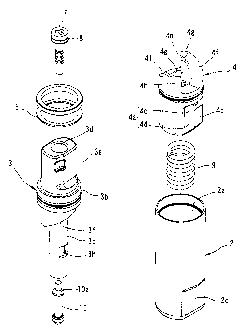
FIG. 7 is an exploded perspective view of the embodiment.
FIG. 8 shows a rotor used in the embodiment. FIG.8(A) is a front
-6-
CA 02710407 2010-06-21
view of the rotor; FIG.8(B) is a side view of the rotor; FIG.8(C) is a
cross-sectional view taken along line C-C of FIG.8(A); and FIG.8(D) is a
cross-sectional view taken along line D-D of FIG.8(B).
FIG. 9 shows the piston used in the embodiment. FIG.9(A) is a front
view of the piston; FIG.9(B) is a side view of the piston; FIG.9(C) is a plan
view of the piston; and FIG.9(D) is a cross-sectional view taken along line
D-D of FIG.9(A).
FIG. 10 is an enlarged cross-sectional view taken along line X-X of
FIG. 1 with a remaining portion of a flat surface portion contacted with a
flat
portion.
FIG. 11 is a view similar to FIG. 10 with an inclined surface portion
contacted with the flat portion.
FIG. 12 is a development view of a main portion showing the
relationship between the rotor and the piston when the rotor is in a closed
position.
FIG. 13 is a view similar to FIG. 12 with the rotor in a standing
position.
FIG. 14 is a view similar to FIG. 12 with the rotor rotated from the
standing position in an opening direction through an abutment angle.
FIG. 15 is a view similar to FIG. 12 with the rotor in an open position.
REFERENCE SIGNS LIST
[0010]
1 rotary damper
2 casing (damper body)
2a receiving hole
2b bottom portion
2c flat portion (stopper means)
3 rotor
-7-
CA 02710407 2010-06-21
3f cam surface (cam mechanism)
3i first restriction surface (movement blocking means)
3j first abutment surface (abutment portion)
4 piston
4c rotation restriction portion (stopper means)
4f cam surface (cam mechanism)
4g second restriction surface (movement blocking means)
4h second abutment surface (abutment portion)
9 coil spring (biasing means)
DESCRIPTION OF EMBODIMENTS
[0011]
A best mode for carrying out the present invention will be described
hereinafter with reference to attached FIGS. 1 to 15.
As shown in FIGS. 1 to 7, a rotary damper 1 according to the present
invention includes a casing (damper body) 2, a rotor 3 and a piston 4.
[0012]
As shown in FIGS. 1 to 7, the casing 2 is composed of a metal
cylindrical body having a circular cross-sectional configuration. An inner
space of the casing 2 is a receiving hole 2a. The receiving hole 2a includes
an opening in one end portion thereof (upper end portion in FIGS. 1 to 7)
(top-bottom direction hereinafter refers to a top-bottom direction in FIGS. 1
to 6) and includes a bottom portion 2b in a lower end portion thereof. A pair
of flat portions (stopper means) 2c, 2c opposed to each other are formed in a
lower end portion of an outer peripheral portion of the casing 2. The pair of
flat portions 2c, 2c are symmetrically arranged with respect to an axis of the
casing 2 and extend parallel to the axis of the casing 2.
[0013]
As shown in FIGS. 1 to 7 and 8, the rotor 3 includes a connecting
-8-
CA 02710407 2010-06-21
portion 3a, a large-diameter portion 3b and a small-diameter portion 3c. The
connecting portion 3a, the large-diameter portion 3b and the small-diameter
portion 3c all have a circular cross-sectional configuration, and are
coaxially
arranged from top to bottom in this order. The large-diameter portion 3b is
fitted to an end portion in the opening side of an inner peripheral surface of
the casing 2 in a rotatable but retained manner with the connecting portion 3a
protruding upward out of the casing 2 and the small-diameter porting 3c
received in the casing 2. By this arrangement, the casing 2 and the rotor 3
are rotationally connected to each other. A gap between the inner peripheral
surface of the casing 2 and an outer peripheral surface of the rotor 3 is
sealed
with a seal member 5 such as an O-ring.
[0014]
The casing 2 and the connecting portion 3a of the rotor 3 are
respectively non-rotatably connected to one and the other of two members that
are rotatably connected with respect to each other, such as a toilet body and
a
toilet lid of a toilet. In this embodiment, for the sake of convenience in the
explanation, it is assumed that the casing 2 is non-rotatably connected to the
toilet body and the connecting portion 3a of the rotor 3 is non-rotatably
connected to the toilet lid. Accordingly, it is assumed that the casing 2 is
non-rotatably fixed in position while the rotor 3 is rotatable with respect to
the casing 2.
[0015]
The toilet lid can be rotated through a range of about 120 degrees
between a closed position in which the toilet lid is abutted against an upper
surface of the toilet body and closes a top end opening of the toilet body and
an open position in which the toilet lid is abutted against a tank mounted on
the toilet body. Accordingly, the rotor 3 is also rotatable between the closed
position and the open position. However, when the rotary damper 1 is used
as an independent unit, to be more specific, when the casing 2 and the rotor 3
-9-
CA 02710407 2010-06-21
are not connected to either one of the two members that are rotatably
connected with respect to each other, the rotor 3 is capable of rotating
slightly
beyond the closed position and the open position, as described later. When
used in a toilet, the rotary damper 1 is arranged such that axes of the casing
2
and the rotor 3 are horizontally oriented.
[0016]
The rotor 3 is rotated together with the toilet lid. Therefore, a
position of the rotor 3 when the toilet lid is in the closed position is also
referred to as the closed position (first rotation position), and a position
of the
rotor 3 when the toilet lid is in the open position is also referred to as the
open
position. A direction in which the rotor is rotated from the closed position
to
the open position is referred to as an opening direction (first direction) and
a
direction in which the rotor is rotated from the open position to the closed
position is referred to as a closing direction (second direction).
[0017]
The rotor 3 includes a through hole 3d formed on the axis thereof.
The through hole 3d extends from an upper end surface to a lower end surface
of the rotor 3. A valve seat 3e having an annular configuration is formed in
an inner peripheral surface of the through hole 3d. The valve seat 3e is
composed of a part of a spherical surface centered on a rotation axis of the
rotor 3. The valve seat 3e has a concave curved surface configuration. The
valve seat 3e is located in an intermediate portion of the small-diameter
portion 3c in the top-bottom direction.
[0018]
A pair of cam surfaces (cam mechanism) 3f, 3f are formed in a lower
end surface of the large-diameter portion 3b. The pair of cam surfaces 3f, 3f
are symmetrically arranged with respect to the axis of the rotor 3. Each of
the cam surfaces extends in a circumferential direction through a length of
about 120 degrees. The small-diameter portion 3c includes first and second
-10-
CA 02710407 2010-06-21
transverse holes 3g, 3h formed therein. The first and second transverse holes
3g, 3h extend from an outer peripheral surface of the small- diameter portion
3c to the inner peripheral surface of the through hole 3d. The first
transverse
hole 3g is located at a generally same location as the cam surface 3f in the
top-bottom direction (direction of the axis of the rotor 3). Therefore, the
first transverse hole 3g is located above the valve seat 3e. The second
transverse hole 3h is located below the valve seat 3e.
[0019]
The piston 4 is received in a portion of the receiving hole 2a between
the bottom portion 2b and the large-diameter portion 3b of the rotor 3 such
that the piston 4 can be moved in the top-bottom direction (direction of the
axis of the casing 2). The piston 4 can be moved between a first position
shown in FIGS. 3 and 6 and a second position shown in FIG. 4. However,
when the rotary damper 1 is used as an independent unit, the piston 4 can be
moved slightly beyond the first position in a direction from the second
position to the first position (downward). On the other hand, as described
later, the piston 4 cannot be moved beyond the second position in a direction
from the first position to the second position (upward). When the rotor 3 is
in the closed position, the piston 4 is located at the first position. When
the
rotor 3 is rotated through a predetermined angle (standing angle of 80 to 90
degrees in this embodiment) from the closed position and reaches a standing
position (second rotational position), the piston 4 is located at the second
position.
[0020]
The piston 4 disposed in the receiving hole 2a divides an inner space
of the receiving hole 2a between the bottom portion 2b and the large-diameter
portion 3b into a first chamber 6A in the bottom portion 2b side and a second
chamber 6B in the large-diameter portion 3b side. The first chamber 6A and
the second chamber 6B communicate with each other through the second
-11-
CA 02710407 2010-06-21
transverse hole 3h, the through hole 3d and the first transverse hole 3g. In
other words, the second transverse hole 3h, the through hole 3d and the first
transverse hole 3g constitute a passage allowing the first chamber 6A and the
second chamber 6B to communicate with each other. The first chamber 6A
and the second chamber 6B are filled with fluid such as viscose fluid (not
shown) introduced through the through hole 3d, the first transverse hole 3g
and the second transverse hole 3h. An opening of the through hole 3d is
sealed with a plug body 7 threaded to the opening and a seal member 8.
[0021]
As shown in FIGS. 3 to 7, and 9, the piston 4 has a circular
cross-sectional configuration. An outer diameter of the piston 4 is sized to
be generally the same as an inner diameter of the receiving hole 2a. An
upper portion of the piston 4 is slidably and rotatably fitted in a portion of
the
inner peripheral surface of the casing 2 that is located above the flat
portions
2c. On the other hand, a pair of flat surface portions 4a, 4a extending
upward from a lower end surface of the piston 4 are formed in a lower portion
of the piston 4. The pair of flat surface portions 4a, 4a respectively
slidably
surface contact inner surfaces of the pair of the flat portions 2c, 2c of the
casing 2. The piston 4 is not rotatable with respect to the casing 2 as long
as
portions of the flat surface portion 4a located in the opposite sides (left
and
right side portions in FIG. 9(A)) with respect to the axis of the piston 4
(axis
of the casing 2) are contacted with the flat portion 2c.
[0022]
An inclined surface portion 4b is formed in the flat surface portion 4a.
The inclined surface portion 4b extends upward from the lower end surface of
the piston 4. A length of the inclined surface portion 4b is shorter than a
length of the flat surface portion 4a by a predetermined length. A one end
(left end) of the inclined surface portion 4b in a width direction thereof
(left-right direction in FIG. 9 (A)) is located at a center in a width
direction of
-12-
CA 02710407 2010-06-21
the flat surface portion 4a. In other words, the one end of the inclined
surface portion 4b in the width direction intersects the flat surface portion
4a
in a central portion of the flat surface portion 4a in the width direction.
The
other end of the inclined surface portion 4b in the width direction intersects
an outer peripheral surface of the piston 4. As shown in FIG. 9(D), the
inclined surface portion 4b is inclined with respect to the flat surface
portion
4a such that the other end of the inclined surface portion 4b in the width
direction is more spaced from the flat surface portion 4a toward the inner
side
of the piston 4 than the one end of the inclined surface portion 4b in the
width
direction.
[00231
The flat surface portion 4a and the inclined surface portion 4b are
contacted with and spaced from (the inner surface of) the flat portion 2c
according to a position of the piston 4 in the axial direction of the casing 2
in
the following manner. That is, when the piston 4 is located at the first
position, a portion (referred to as a rotation restriction portion (stopper
means) hereinafter) 4c of the flat surface portion 4a located above the
inclined
surface portion 4b is entirely contacted with the flat portion 2c in the width
direction. Accordingly, when the piston 4 is located at the first position,
the
piston 4 is not rotatable with respect to the casing 2. The rotational
position
of the piston 4 at this time is an initial position. Although a contact length
of the rotation restriction portion 4c with respect to the flat portion 2c in
the
top-bottom direction is reduced as the piston 4 is moved upward from the first
position, the rotation restriction portion 4c is contacted with the flat
portion
2c, thereby holding the piston 4 in a non-rotatable manner until the piston 4
reaches a position immediately before the second position. When the piston
4 reaches the second position, a lower end of the rotation restriction portion
4c generally coincides with an upper end of the flat portion 2c or is slightly
spaced upward from the upper end of the flat portion 2c, and thus the entirety
- 13 -
CA 02710407 2010-06-21
of the rotation restriction portion 4c is spaced upward from the flat portion
2c.
In this condition, as shown in FIGS. 10 and 11, only the inclined surface
portion 4b and a portion (referred to as a remaining portion hereinafter) 4d
of
the flat surface portion 4a other than the rotation restriction portion 4c are
opposed to the flat portion 2c. Accordingly, when the piston 4 reaches the
second position, as shown in FIG. 10, the piston 4 is prevented from being
rotated in a direction from the remaining portion 4d toward the inclined
surface portion 4b (direction of arrow A in FIG. 10) by the abutment of the
remaining portion 4d against the flat portion 2c. However, as shown in FIG.
11, the piston 4 can be rotated in a direction from the inclined surface
portion
4b toward the remaining portion 4d (direction of arrow B in FIG. 10) until the
inclined surface portion 4b is abutted against the flat portion 2c. In other
words, the piston 4 can be rotated through an inclination angle of the
inclined
surface portion 4b with respect to the flat surface portion 4a.
[0024]
Here, the direction from the remaining portion 4d toward the inclined
surface portion 4b coincides with the closing direction and the direction from
the inclined surface portion 4b toward the remaining portion 4d coincides
with the opening direction. Accordingly, when the piston 4 reaches the
second position, the piston 4 becomes rotatable between the initial position
and a terminal position spaced from the initial position by the inclination
angle of the inclined surface portion 4b in the opening direction. However,
even when the piston 4 reaches the second position, the piston 4 is not
rotatable in the closing direction.
[0025]
An insertion hole 4e is formed in the piston 4 on the axis of the piston
4 from an upper end surface to the lower end surface of the piston 4. The
small-diameter portion 3c of the rotor 3 is rotatably and slidably inserted in
an
upper portion of the insertion hole 4e. A coil spring (biasing means) 9 is
- 14-
CA 02710407 2010-06-21
disposed in an annular space between an inner peripheral surface of the
insertion hole 4e and the outer peripheral surface of the small-diameter
portion 3c. A lower end portion of the coil spring 9 is abutted against the
bottom portion 2b and an upper end portion of the coil spring 9 is abutted
against the piston 4, thereby the coil spring 9 biasing the piston 4 toward
the
large-diameter portion 3b of the rotor 3.
[0026]
A pair of cam surfaces (cam mechanisms) 4f, 4f are formed in an upper
end surface of the piston 4 opposed to the large-diameter portion 3b. The
cam surface 4f is abutted against the cam surface 3f by the biasing force of
the
coil spring 9. A lower end portion of the cam surface 3f is contacted with an
upper end portion of the cam surface 4f when the rotor 3 is in the closed
position (see FIG. 12). The piston 4 is located at the first position at this
time. The cam surfaces 3f, 4f allow the piston 4 to be moved in the direction
from the first position toward the second position (upward) when the rotor 3
is
rotated from the closed position in the opening direction (the direction of
Arrow A in FIG. 12). Accordingly, when the rotor 3 is rotated in the opening
direction, the piston 4 is moved from the first position side toward the
second
position side by the coil spring 9. The cam surfaces 3f, 4f causes the piston
4 to be moved from the second position side toward the first position side
against the biasing force of the coil spring 9 when the rotor 3 is rotated in
the
closing direction.
[0027]
The piston 4 can be moved downward beyond the first position until
the lower end surface of the piston 4 is abutted against the bottom portion
2b,
according to which the rotor 3 can be rotated through a slight angle (5
degrees,
for example) beyond the closed position. However, when the rotary damper
1 is used in a toilet, as mentioned above, the abutment of the toilet lid
against
the toilet body prohibits the rotor 3 from being rotated beyond the closed
-15-
CA 02710407 2010-06-21
position. Therefore, the piston 4 will not be moved downward beyond the
first position.
[0028]
As shown in FIGS. 12 to 15, the rotor 3 includes a first restriction
surface 3i formed therein. The first restriction surface 3i extends in the
opening direction from a lower end of the cam surface 3f. The first
restriction surface 3i is composed of a flat surface disposed at a right angle
with respect to the axis of the casing 2. On the other hand, the piston 4
includes a second restriction surface 4g formed therein. The second
restriction surface 4g extends in the closing direction from an upper end of
the
cam surface 4f. The second restriction surface 4g is composed of a flat
surface disposed at a right angle with respect to the axis of the casing 2.
Abutment of the first restriction surface 3i against the upper end surface of
the piston 4, abutment of the second restriction surface 4g against a lower
end
surface of the large-diameter portion 3b of the rotor 3 or respective abutment
of the first and second restriction surfaces 3i, 4g against the upper end
surface
of the piston 4 and the lower end surface of the large-diameter portion 3b
prohibits the piston 4 from being moved further upward. The piston 4 is
located at the second position at this time. Therefore, the piston 4 cannot be
moved upward beyond the second position. As mentioned above, when the
piston 4 is moved from the first position to the second position, the rotor 3
is
rotated from the closed position through 80 to 90 degrees to reach the
standing position.
[0029]
The rotor 3 includes a first abutment surface (abutment portion) 3j
formed therein. The first abutment surface 3j extends from a distal end of
the first restriction surface 3i to the lower end surface of the large-
diameter
portion 3b. The first abutment surface 3j is formed at a right angle with
respect to the first restriction surface 3i and faces the opening direction.
The
-16-
CA 02710407 2010-06-21
piston 4 includes a second abutment surface (abutment portion) 4h formed
therein. The second abutment surface 4h extends from a distal end of the
second restriction surface 4g to the upper end surface of the piston 4. The
second abutment surface 4h is formed at a right angle with respect to the
second restriction surface 4g and faces the closing direction. The second
abutment surface 4h is arranged such that when the piston 4 reaches the
second rotation position accompanying the rotation of the rotor 3 to the
standing position, the second abutment surface 4h is spaced from the first
abutment surface 3j by a predetermined distance in the circumferential
direction (see FIG. 13). Therefore, the rotor 3 can be rotated with respect to
the piston 4 in the initial position through an angle (referred to as an
abutment
angle hereinafter) corresponding to a distance between the first abutment
surface 3j and the second abutment surface 4h from the standing position
(second rotation position) in the opening direction. The rotation position of
the rotor 3 when the first abutment surface 3j is abutted against the second
abutment surface 4h of the piston 4 in the initial position is a third
rotation
position (see FIG. 14). After the abutment of the first abutment surface 3j
and the second abutment surface 4h against each other, the rotor 3 can be
further rotated in the opening direction together with the piston 4 through
the
inclination angle of the inclined surface portion 4b with respect to the flat
surface portion 4a (see FIG. 15). Here, the position of the rotor 3 at this
time
is referred to as a maximum rotation position. The maximum rotation position
is beyond the open position by slight degrees (5 degrees, for example) in the
direction from the closed position to the open position. Accordingly, when
the rotary damper 1 is used in a toilet, the rotor 3 is not rotated up to the
maximum rotation position, stopped at a position before the maximum rotation
position by a predetermined angle (This position is the open position.).
[0030]
As shown in FIGS. 3 to 6, a valve body 10 is inserted in a portion of
-17-
CA 02710407 2010-06-21
the through hole 3d located below the valve seat 3e such that the valve body
is movable in the top-bottom direction (longitudinal direction of the
through hole 3d). The valve body 10 is movable between a closed-valve
position shown in FIGS. 5 and 6 and an open-valve position shown in FIGS. 3
and 4. When the valve body 10 is located at the closed-valve position, a
valve portion 10a of the valve body 10 is seated on the valve seat 3e,
blocking
the communication between a portion of the through hole 3d above the valve
seat 3e and the portion of the through hole 3d below the valve seat 3e. As a
result, the communication between the first chamber 6A and the second
chamber 6B is blocked. On the other hand, when the valve body 10 is in the
open-valve position, the valve portion l0a is spaced downward from the valve
seat 3e. As a result, the first chamber 6A and the second chamber 6B can
communicate with each other through the through hole 3d.
[0031 ]
Movement of the valve body 10 between the open-valve position and
the closed-valve position is automatically performed accompanying the
rotation of the rotor 3. That is, when the rotor 3 is rotated in the opening
direction and the piston 4 is moved upward accompanying the rotation of the
rotor 3, the fluid in the second chamber 6B flows into the first chamber 6A
through the through hole 3d. The fluid flowing downward in the through
hole 3d pushes the valve body 10 downward, causing the valve body 10 to be
moved to the open-valve position. On the other hand, when the rotor 3 is
rotated in the closing direction, and the piston 4 is moved downward
accompanying the rotation of the rotor 3, the fluid in the first chamber 6A
flows into the second chamber 6B through the through hole 3d. The fluid
flowing upward in the through hole 3d pushes the valve body 10 upward,
causing the valve body 10 to be moved to the closed-valve position.
[0032]
As shown in FIGS. 3 to 6 and 9, an annular recess 4i is formed in the
-18-
CA 02710407 2010-06-21
outer peripheral surface of the piston 4. A depth of the annular recess 4i
increases progressively downward. Therefore, a bottom surface of the
annular recess 4i has a tapered surface configuration with the diameter of the
bottom surface reduced progressively downward. A seal member 11 such as
an O-ring made of an elastic material such as rubber is disposed in the
annular
recess 4i. An inner diameter of the seal member 11 is sized to be smaller
than a diameter of the bottom surface of the annular recess 4i at the deepest
portion. Therefore, the seal member 11 is constantly pressed against the
bottom surface of the annular recess 4i by its own elasticity. An outer
diameter of the seal member 11 is sized such that an outer peripheral portion
of the seal member 11 is protruded outward from the annular recess 4i even
when the seal member 11 is disposed at the deepest portion of the annular
recess 4i. Accordingly, the outer peripheral portion of the seal member 11 is
protruded outward from the annular recess 4i and is press contacted against an
inner peripheral surface of the receiving hole 2a by its own elasticity. By
this arrangement, a gap between the outer peripheral surface of the piston 4
and the inner peripheral surface of the receiving hole 2a is sealed. A
diameter of a member constituting the seal member 11 is sized to be smaller
than a width (dimension in the top-bottom direction) of the annular recess 4i.
Therefore, the seal member 11 can be moved through a distance corresponding
to a difference between the width of the annular recess 4i and the diameter of
the member constituting the seal member 11 in the top-bottom direction. The
seal member 11 can be moved downward more easily than upward since the
bottom surface of the annular recess 4i is tapered such that the diameter of
the
bottom surface is reduced progressively downward.
[0033]
Let us assume that the toilet lid (rotor 3) is in the closed position (first
rotation position) in a toilet in which the rotary damper 1 having the
above-described features is used. At this time, the piston 4 is located at the
-19-
CA 02710407 2010-06-21
first position, the valve body 10 is located at the open-valve position and
the
seal member 11 is located at an upper end portion of the annular recess 4i.
Furthermore, as shown in FIG. 12, a lower end portion of the cam surface 3f is
abutted against an upper end portion of the cam surface 4f. At this time, the
toilet lid is not rotated in the opening direction by the coil spring 9 since
the
rational biasing force of the coil spring 9 is smaller than a rotation moment
generated by an own weight of the lid in the closed position, although the
toilet lid is rotationally biased in the opening direction by the biasing
force of
the coil spring 9 when the toilet lid is in the closed position.
[0034]
When the toilet lid is manually rotated in the opening direction from
the closed position, the piston 4 is moved from the first position to the
second
position by the coil spring 9. At this time, according to the movement of the
piston 4, the fluid in the second chamber 6B flows into the first chamber 6A
through the though hole 3d. The fluid flows almost without resistance since
the valve body 10 is located at the open-valve position. Therefore, the toilet
lid can be rotated in the opening direction easily and at a high speed.
[0035]
The piston 4 can be more easily moved at the beginning of the rotation
of the toilet lid from the closed position since the seal member 11 is moved
relatively downward according to the movement of the piston 4. To be more
specific, if the seal member 11 were disposed in the piston 4 non-movably in
the top-bottom direction, the piston 4 would have to be moved against a
friction resistance generated between the seal member 11 and the inner
peripheral surface of the receiving hole 2a when the piston starts to be moved
from the first position. Accordingly, a considerable moving resistance is
generated at the beginning of the movement of the piston 4, not allowing the
toilet lid to be rotated smoothly in the opening direction. However, in the
rotary damper 1 of the present invention, at the beginning of the movement of
-20-
CA 02710407 2010-06-21
the piston 4, the seal member 11 is relatively moved in the opposite direction
from the piston 4, i.e. downward. Moreover, since the diameter of the
bottom surface of the annular recess 4i is reduced progressively downward,
the seal member 11 is moved more smoothly downward. Therefore, the
piston 4 can be smoothly moved from the first position to the second position.
Accordingly, the toilet lid can be smoothly rotated in the opening direction
from the closed position. The seal member 11 reaches a lower end portion of
the annular recess 4i while the piston 4 is moved toward the second position.
In the process, the diameter of the seal member 11 is reduced according the
reduction of the diameter of the bottom surface of the annular recess 4i in
the
lower end portion of the annular recess 4i. This reduces the friction
resistance generated between the seal member 11 and the inner peripheral
surface of the receiving hole 2a. Therefore, the piston 4 can be smoothly
moved upward.
[0036]
When the toilet lid is rotated in the opening direction from the closed
position through a predetermined angle (70 degrees, for example), a rotation
moment generated by the coil spring 9 and the cam surfaces 3f, 4f becomes
greater than the rotation moment in the closing direction generated by the own
weight of the toilet lid. Therefore, after this point, the toilet lid is
automatically rotated in the opening direction to a standing position. The
rotation moment generated by the coil spring 9 may be set to be always
smaller than the rotation moment generated by the own weight of the toilet
lid.
In this case, the toilet lid should be manually rotated from the closed
position
to the standing position.
[0037]
When the toilet lid (rotor 3) is rotated in the opening direction to the
standing position (second rotation position), the piston 4 reaches the second
position. At this time, as shown in FIG. 13, the first restriction surface 3i
is
-21-
CA 02710407 2010-06-21
abutted against the upper end surface of the piston 4 or the second
restriction
surface 4g is abutted against the lower end surface of the large-diameter
portion 3b of the rotor 3. This prohibits the piston 4 from being moved
upward, causing the rotational biasing force not to be generated by the coil
spring 9. As a result, the toilet lid and the rotor 3 are stopped at the
standing
position. Accordingly, the toilet lid can be prevented from being rotated to
the open position by the biasing force of the coil spring 9 and from being
abutted against the tank. Therefore, the generation of a hitting sound can be
prevented. When the toilet lid in the standing position is set free to be
rotated, the toilet lid would be rotated to the closed position since the
standing position is spaced from the closed position by 80 to 90 degrees.
However, the rotation moment in the closing direction generated by the own
weight of the toilet lid at the standing position is smaller than the rotation
moment generated by the coil spring 9 and the cam surfaces 3f, 4f.
Therefore, the toilet lid is prohibited from being rotated in the closing
direction from the standing position by the biasing force of the coil spring
9.
The toilet lid is thus held in a stopped condition at the standing position.
[0038]
The toilet lid is manually rotated in the opening direction from the
standing position to the open position. When the toilet lid is rotated in the
opening direction from the standing position, the rotor 3 is rotated in the
opening direction. Accompanying the rotation of the rotor 3 in the opening
direction from the standing position (second rotation position), the cam
surfaces 3f, 4f are spaced from each other and the first and the second
abutment surfaces 3j, 4h are moved closer to each other. When the rotor is
rotated from the standing position through the abutment angle, the first
abutment surface 3j is abutted against the second abutment surface 4h as
shown in FIG. 14. Accordingly, after the abutment, the rotor 3 and the piston
4 are rotated together in the opening direction. When the toilet lid reaches
-22-
CA 02710407 2010-06-21
the open position and stops there, the rotor 3 and the piston 4 are stopped at
the open position as shown in FIG. 15. When the toilet lid is rotated in the
opening direction from the standing position, the rotor 3 and the piston 4 are
rotated together in the opening direction through an inclination angle of the
inclined surface portion 4b. After that, only the rotor 3 may be rotated to
the
open position. The first and the second abutment surfaces 3j, 4h will not be
abutted against each other at this time. It is because the maximum rotation
position of the rotor 3 is located more to the front than the open position in
the opening direction by a predetermined angle.
[0039]
At least one of the first restriction surface 3i and the second restriction
surface 4g are formed to prevent the toilet lid from being abutted against the
tank by the biasing force of the coil spring 9. If the rotor 3 were prohibited
from being rotated by the prohibition of the movement of the piston 4 by the
first or the second restriction surface 3i, 4g, a rotation range of the rotor
3
would be limited. However, in the rotary damper 1, the rotation range of the
rotor 3 can be wide since the rotor 3 is rotatable in the opening direction
with
respect to the piston 4 through the predetermined abutment angle even after
the piston 4 is stopped at the second position. Moreover, when the piston 4
reaches the second position, the piston 4 can be rotated in the opening
direction through the predetermined inclination angle from the initial
position.
This arrangement allows the rotation range of the rotor 3 to be even wider.
[0040]
To move the toilet lid from the open position to the closed position,
the toilet lid is first manually rotated in the closing direction from the
open
position. When the rotor 3 is rotated in the closing direction from the open
position through a predetermined angle (abutment angle or an angle equal to
the abutment angle minus the inclination angle), the cam surface 3f is abutted
against the cam surface 4f. After the abutment, therefore, the rotor 3 and the
-23-
CA 02710407 2010-06-21
piston 4 are rotated together in the closing direction to the standing
position.
[0041 ]
When the toilet lid in the standing position is further rotated in the
closing direction, the piston 4 is moved downward by the cam surfaces 3f, 4f
against the biasing force of the coil spring 9. Accompanying the downward
movement of the piston 4, the fluid in the first chamber 6A is moved to flow
into the second chamber 6B. At this time, the valve body 10 is moved
upward by the fluid to be seated on the valve seat 3e. This causes the
through hole 3d that serves as a passage between the first chamber 6A and the
second chamber 6B to be closed. As a result, the fluid in the first chamber
6A flows into the second chamber 6B through a slight gap between the outer
peripheral surface of the small-diameter portion 3c of the rotor 3 and the
inner
peripheral surface of the insertion hole 4e of the piston 4. The speed of the
downward movement of the piston 4 is reduced by a flow resistance of the
fluid passing though the gap. This causes the rotational speed of the toilet
lid in the closing direction to be reduced. Moreover, when the piston 4 is
moved downward from the second position by a predetermined distance, the
seal member 11 is moved to the upper end portion of the annular recess 4i,
strongly press-contacted with the inner peripheral surface of the receiving
hole 2a. Accordingly, a big friction resistance is generated between the seal
member 11 and the inner peripheral surface of the receiving hole 2a. This
friction resistance also works to reduce the speed of the downward movement
of the piston 4. While, in the rotary damper 1 of this embodiment, the slight
gap between the outer peripheral surface of the small-diameter portion 3c and
the inner peripheral surface of the insertion hole 4e of the piston 4 is used
as
flow resistance means against the fluid, alternatively, the slight gap may be
reduced to practically zero and an orifice as a resistance passage
communicating with the first and the second chambers 6A, 6B may be formed
in the small-diameter portion 3c or the piston 4.
-24-
CA 02710407 2010-06-21
[0042]
When the toilet lid reaches the closed position, the rotor 3 is stopped
at the closed position (first rotation position), and the piston 4 is stopped
at
the first position. While the piston 4 can be moved downward from the first
position, the piston 4 will not be moved downward from the first position
since the piston 4 is biased upward by the coil spring 9. The valve body 10
is located at the closed-valve position as shown in FIG. 6 immediately after
the toilet lid reaches the closed position. However, when pressures in the
first and the second chambers 6A, 6B become generally equal to each other
with the passage of a predetermined amount of time after the toilet lid
reaches
the closed position, the valve body 10 is moved downward by its own weight
and is stopped at the open-valve position. This returns the rotary damper 1
to an initial condition as shown in FIG. 3.
[0043]
Although particular embodiments of the invention have been described
above, it will be understood that various modifications may be made without
departing from the scope of the invention described herein.
For example, in the above-described embodiment, the rotation range of
the rotor 3 is widened by adopting the two arrangements: i.e., making the
rotor 3 rotatable with respect to the piston 4 through the abutment angle; and
making the piston 4 rotatable though the inclination angle. Instead of
adopting both of these arrangements, adopting only one may serve the
purpose.
Moreover, in a case where the piston 4 is rotatable between the initial
position and the terminal position as in the above-described embodiment, the
first and the second abutment surfaces 3j, 4h may be arranged to be abutted
against each other when the rotor 3 is rotated to the second rotation
position.
In this case, the position of the rotor 3 when the rotor 3 is rotated with the
piston 4 from the second rotation position in the opening direction (one
-25-
CA 02710407 2010-06-21
direction) through the angle between the initial position and the terminal
position is the third rotation position. The third rotation position may be
arranged to coincide with the open position of the toilet lid or may be a
position more to the front than the open position in the opening direction by
the predetermined angle.
Moreover, in a case where the rotor 3 is rotatable from the second
rotation position to the third rotation position with respect to the piston 4
in
the initial position, the piston 4 may be made non-rotatable in the opening
direction (one direction) from the initial position.
INDUSTRIAL APPLICABILITY
[0044]
The damper apparatus according to the present invention may be used
as a damper apparatus disposed between the toilet body and the toilet lid for
controlling the rotation of the toilet lid in the closing direction to be
rotated at
low speed.
-26-