Note : Les descriptions sont présentées dans la langue officielle dans laquelle elles ont été soumises.
CA 02712181 2010-08-05
1
MODULAR CONVEYOR BELT
FIELD OF THE INVENTION
s The present invention generally relates to a modular conveyor belt. More
particularly,
it relates to a modular conveyor belt comprising a plurality of belt modules
fastened
to the conveyor in such a way as to enable the belt modules to be easily
removable.
BACKGROUND OF THE INVENTION
Conveyor belts are widely used in numerous industries to easily move material
from
one place to another. Such conveyors normally comprise a plurality of belt
modules
that are usually arranged in a parallel configuration. This modularity of the
conveyor
belts constitutes an important characteristic as it enables the design of
conveyor
belts with removable belt modules. Removability of the modules offers several
advantages. For example, belt modules that are easily removable allow the
modules
to be interchanged with other modules having different upper surface shapes in
order to accommodate the various shapes and sizes of the material that may be
carried by the conveyor. Moreover, in the food industry, rigorous sanitary
needs call
for a conveyor where the components that are in contact with the food are
easily
cleanable. On this point, belt modules that are easily removable provide a
useful
solution as it greatly facilitates the cleaning of these modules.
Several different prior art devices providing removable belt modules that are
part of
their structure are known to the Applicant.
US 2,679,954 (Powell) discloses a conveyor with removable individual modules
that
can be attached to the conveyor structure. The modules are attached to the
conveyor structure using the flexibility of the module to introduce one side
of the
module within an opening in the structure.
CA 02712181 2010-08-05
2
US 6,176,370 (Davies) teaches another conveyor with easily removable
individual
modules. According to this invention the modules are attached to the slats of
the
frame using protrusions extending from the module in a perpendicular direction
to
the displacement of the module on the conveyor, the protrusions fitting inside
corresponding slots.
US 6,554,129 (Straight et al.) teaches a conveyor using a modular conveyor
belt
where individual attachment elements are attached to the belt modules using
two
sets of appendages for locking the attachment elements between two sets of
consecutive side by side belt modules. According to this invention, the belt
modules
are held together using hinge pins traversing the ends of the belt modules.
Other devices known to the Applicant include US 4,134,181 (Schneider Jr.),
US 5,628,393 (Steeber et al.), US 5,725,424 (Dufour et al.), US 6,358,135
(Post),
US D473,032 (Altom), US 6,811,021 (Corley), US 7,111,725 (Marshall et al.),
US 7,584,837 (Roether et al.) and US 2006/0030251 (Dufour et al.).
However, none of the prior art documents cited above includes a mechanism
using a
fastener locking against a vertical locking pin extending outwardly from the
conveyor
to provide quick removal of the belt modules, while maintaining the modules
firmly in
place when attached to the conveyor.
Consequently, there is presently a need for a modular conveyor belt having the
above-mentioned characteristics in order to hold the modules tightly in place
while
offering a fast and easy removal mechanism of the modules from the conveyor,
such
a system being capable of operating reliably over a long period of time.
CA 02712181 2010-08-05
3
SUMMARY OF THE INVENTION
An object of the present invention is to provide a modular conveyor belt
device that
addresses at least one of the above-mentioned needs.
According to the present invention, there is provided a modular conveyor belt
comprising at least one driving chain and a plurality of belt modules
extending
transversally and parallely mounted over an entire length of the at least one
driving
chain, each belt module comprising:
- at least one bottom opening located underneath the belt module, wherein
each bottom opening is shaped to receive a locking pin extending
outwardly from the at least one driving chain, the locking pin comprising
at least one notch;
at least one side opening intersecting with the corresponding at least one
bottom opening;
a fastener removably mounted in each of the at least one side opening,
each fastener comprising a projection positionable between a locked
configuration wherein the projection is embedded into one of the at least
one notch of the locking pin and a released configuration wherein the
projection is disembedded from the corresponding at least one notch of
the locking pin.
Another aspect of the invention concerns a belt module for use on the modular
conveyor referred to in the previous paragraph. The characteristics of the
belt
module, according to this second aspect of the invention, are exactly the same
as
the ones that were described above when referring to the belt modules
comprised in
the modular conveyor belt.
The use of the fastener removably mounted in the side opening of the belt
module
for locking against a locking pin going trough the bottom opening of the belt
module
CA 02712181 2010-08-05
4
provides a solution with excellent locking capabilities, while offering fast
and easy
removal of the belt modules.
The objects, advantages and features of the present invention will become more
apparent upon reading the following non-restrictive description of preferred
embodiments thereof, given for the purpose of exemplification only, with
reference to
the accompanying drawings.
BRIEF DESCRIPTION OF THE DRAWINGS
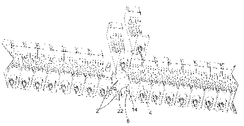
Figure 1 is a perspective view of a portion of a conveyor belt in accordance
with a
preferred embodiment of the present invention, wherein one belt module is
removed;
Figure 2 is a perspective view of a belt module in accordance with a preferred
embodiment of the present invention;
Figure 3 is another perspective view of the belt module in accordance with a
preferred embodiment of the present invention, highlighting the locking
mechanism
and presented herewith in a locked configuration;
Figure 4 is yet another perspective view of the belt module in accordance with
a
preferred embodiment of the present invention, highlighting the locking
mechanism
and presented herewith in a released configuration
DETAILED DESCRIPTION OF PREFERRED EMBODIMENTS OF THE
INVENTION
in the following description, the same numerical references refer to similar
elements.
The embodiments shown in the figures are preferred.
CA 02712181 2010-08-05
Although the preferred embodiments of the present invention are illustrated in
the
accompanying drawings and although the preferred embodiments of the locking
mechanism of the modular conveyor belt as shown consist of certain geometrical
configurations as explained and illustrated herein, not all of these
components and
5 geometries are essential to the invention and thus should not be taken in
their
restrictive sense, i.e. should not be taken as to limit the scope of the
present
invention. It is to be understood, as also apparent to a person skilled in the
art, that
other suitable components and cooperations thereinbetween, as well as other
suitable geometrical configurations may be used for the locking mechanism of
the
modular conveyor belt and corresponding parts according to the present
invention,
as briefly explained and inferred herein, without departing from the scope of
the
invention.
Referring to Figure 1, where a modular conveyor belt device according to a
preferred
embodiment is shown, the device comprises two parallel driving chains 2 on
which
are attached a plurality of belt modules 4 extending transversally and mounted
over
the entire length of the driving chains 2. The belt modules 4, are preferably
made of,
but not limited to, a rigid plastic material such as nylon. Locking pins 6 are
mounted
on plates that are themselves mounted onto the chains 2, through soldering or
other
mounting techniques. The locking pins 6 located on a single chain are arranged
at a
constant distance from one another as to consequently allow the belt modules
mounted on the locking pins 6 to be evenly disposed over the conveyor.
Moreover
the corresponding locking pins 6 on both chains 2 are horizontally aligned in
order to
allow the belt modules to consequently be parallely mounted over the conveyor.
Each locking pin comprises a notch 14.
As shown in Figures 2 to 4, the belt modules 4, according to the present
invention
are designed to interact with the locking mechanism disclosed herewith. In the
illustrated embodiment, the belt module comprises two bottom openings 12
located
underneath the belt module 4. Each bottom opening is shaped to receive the
locking
CA 02712181 2010-08-05
6
pin 6 extending outwardly from the chains 2. The illustrated belt module 4
also
comprises two side openings 8 each intersecting with their corresponding
bottom
opening 12. The side openings 8 are located on both ends of the belt modules
4.
According to this preferred embodiment, the side openings 8 of the belt
modules 4
are threaded in order to allow each fastener 10 to be threadably mounted in
the side
openings 8. However, the fastener 10 can be mounted in the side openings 8
using
several other methods know to the person skilled in the art. For example, and
without limitation, the fastener 10 may comprise magnetic properties that urge
the
fastener 10 to attach itself to the locking pin 6, while being releasable for
removal
and maintenance of the belt module 4.
The fasteners 10 also comprise a projection 16 positionable between a locked
configuration and a released configuration. The locked configuration is shown
in
Figure 3, wherein the projection 16 is embedded into the notch 14 of the
locking pin
6. In contrast, the released configuration is shown in Figure 4, wherein the
projection
16 is disembedded from the corresponding notch 14 of the locking pin 6. The
displacement of the projection 16, from a locked to a released configuration
can be
controlled by an operator with a corresponding displacement of the fastener
18. In
the illustrated embodiment, this displacement of the projection 16 is achieved
by
screwing the fastener in or out of the side opening. The extremity of the
fastener 18
can be attached to a handle 20 for convenience of use.
Preferably, as better shown in Figures 3 and 4, the side opening 8 and bottom
opening 12 of each pair of openings are perpendicular to one another, but the
locking mechanism presented herewith can also function with pair of openings
that
are not perpendicular to one another as long as they intersect in such a way
as to
allow the projection 16 comprised in the fastener 10 to be embedded into the
notch
14 of the locking pin 6.
CA 02712181 2010-08-05
7
Preferably, as better shown in Figures 1 and 2, the top of each locking pin 6
comprises an alignment surface 22 for aligning the bottom opening 12 with the
corresponding locking pin 6 during its insertion thereof. According to this
preferred
embodiment, the alignment surface 22 of the locking pin 6 is conically shaped
to
guide the locking pin 6 into the corresponding bottom opening 12 whenever the
bottom opening 12 is lowered on the locking pin 6, therefore reducing the need
to
initially align both elements perfectly when proceeding with the addition of a
belt
module 4 on the conveyor.
Preferably, as better shown in Figures 3 and 4, the side opening 8 and bottom
opening 12 of each pair of openings are perpendicular to one another, but the
locking mechanism presented herewith can also function with pair of openings
that
are not perpendicular to one another as long as they intersect in such a way
as to
allow the projection 16 comprised in the fastener 10 to be embedded into the
notch
14 of the locking pin 6.
According to this preferred embodiment, the surface of each belt module is
also
shaped with an inward concavity in order to allow better support for round
shape
material while they are being carried on the conveyor.
Although preferred embodiments of the present invention have been described in
detail herein and illustrated in the accompanying drawings, it is to be
understood that
the invention is not limited to these precise embodiments and that various
changes
and modifications may be effected therein without departing from the scope or
spirit
of the present invention.