Sélection de la langue

Search

Sommaire du brevet 2712796 

Énoncé de désistement de responsabilité concernant l'information provenant de tiers

Une partie des informations de ce site Web a été fournie par des sources externes. Le gouvernement du Canada n'assume aucune responsabilité concernant la précision, l'actualité ou la fiabilité des informations fournies par les sources externes. Les utilisateurs qui désirent employer cette information devraient consulter directement la source des informations. Le contenu fourni par les sources externes n'est pas assujetti aux exigences sur les langues officielles, la protection des renseignements personnels et l'accessibilité.

Disponibilité de l'Abrégé et des Revendications

L'apparition de différences dans le texte et l'image des Revendications et de l'Abrégé dépend du moment auquel le document est publié. Les textes des Revendications et de l'Abrégé sont affichés :

  • lorsque la demande peut être examinée par le public;
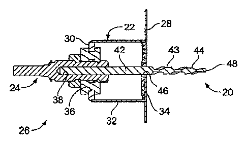
  • lorsque le brevet est émis (délivrance).
(12) Demande de brevet: (11) CA 2712796
(54) Titre français: SCIE A PERCER MUNIE D'UN FORET PILOTE DE FORME CONIQUE
(54) Titre anglais: HOLE SAW WITH TAPERED PILOT BIT
Statut: Réputée abandonnée et au-delà du délai pour le rétablissement - en attente de la réponse à l’avis de communication rejetée
Données bibliographiques
(51) Classification internationale des brevets (CIB):
  • B23B 51/02 (2006.01)
  • B23B 51/05 (2006.01)
(72) Inventeurs :
  • MOFFATT, WILBUR K. (Etats-Unis d'Amérique)
(73) Titulaires :
  • TEXTRON INNOVATIONS INC.
(71) Demandeurs :
  • TEXTRON INNOVATIONS INC. (Etats-Unis d'Amérique)
(74) Agent: SMART & BIGGAR LP
(74) Co-agent:
(45) Délivré:
(22) Date de dépôt: 2010-08-03
(41) Mise à la disponibilité du public: 2011-02-06
Licence disponible: S.O.
Cédé au domaine public: S.O.
(25) Langue des documents déposés: Anglais

Traité de coopération en matière de brevets (PCT): Non

(30) Données de priorité de la demande:
Numéro de la demande Pays / territoire Date
61/231,722 (Etats-Unis d'Amérique) 2009-08-06

Abrégés

Abrégé anglais


The present invention provides a hole saw and pilot bit assembly. The pilot
bit of the
assembly has a portion which is devoid of flute and lobes and a portion
including
flutes and lobes. The portion including flutes and lobes further includes a
portion
which is tapered.

Revendications

Note : Les revendications sont présentées dans la langue officielle dans laquelle elles ont été soumises.


The invention is claimed as follows:
1. A pilot bit comprising:
a shank including a first portion having a proximal end and a distal end, a
second portion having a proximal end and a distal end, said second portion
extending
from said distal end of said first portion, and a third portion having a
proximal end
and a tip, said third portion extending from said distal end of said second
portion;
wherein said first portion is devoid of flutes and devoid of lobes;
wherein the outermost diameter of said second portion is consistent from said
proximal end to said distal end thereof; and
wherein the outermost diameter of said third portion tapers inwardly along a
length of the third portion from the proximal end to the tip.
2. A pilot bit as defined in claim 1, wherein said first portion comprises
approximately two-thirds the length of the pilot bit.
3. A pilot bit as defined in claim 1, wherein said second and third portions
extend
approximately one-third the length of the pilot bit.
4. A pilot bit as defined in claim 1, wherein the angle of taper is
approximately
three degrees.
5. A hole saw and pilot bit combination comprising:
a hole saw having a back plate, a skirt depending from said back plate, and a
cutting edge at a distal end of said skirt; and
a pilot bit comprising, a shank including a first portion having a proximal
end
and a distal end, a second portion having a proximal end and a distal end,
said second
portion extending from said distal end of said first portion, and a third
portion having
a proximal end and a tip, said third portion extending from said distal end of
said
second portion;
6

wherein said first portion is devoid of flutes and devoid of lobes,
wherein the outermost diameter of said second portion is consistent from said
proximal end to said distal end thereof; and
wherein the outermost diameter of said third portion tapers inwardly along a
length of said third portion from the proximal end to the tip.
6. The combination as defined in claim 5, wherein said fast portion of said
pilot
bit extends approximately two-thirds the length of the pilot bit.
7. The combination as defined in claim 5, wherein said second and third
portions
of said pilot bit extend approximately one-third the length of the pilot bit.
8. The combination as defined in claim 5, wherein the angle of taper of said
pilot
bit is approximately three degrees.
9. The combination as defined in claim 5, wherein the distal end of said first
portion of said pilot bit extends distally beyond said cutting edge of said
hole saw.
10. The combination as defined in claim 9, wherein the distal end of said
first
portion of said pilot bit extends distally beyond said cutting edge of said
hole saw by
approximately 0.05 inches.
7

Description

Note : Les descriptions sont présentées dans la langue officielle dans laquelle elles ont été soumises.

CA 02712796 2010-08-03
1913/479771443
PATENT
HOLE SAW WITH TAPERED PILOT BIT
10001] This application claims the domestic benefit of United States
Provisional
application Serial No. 61/231,722, filed on August 6, 2009, which disclosure
is
hereby incorporated by reference in its entirety.
BACKGROUND OF THE INVENTION
[0002] Hole saws are commonly used in connection with electric drills to
create
holes in a workpiece, such as sheet metal.
SUMMARY OF THE INVENTION
[0003] The present invention provides a hole saw and pilot bit assembly. The
pilot bit of the assembly has a portion which is devoid of flute and lobes and
a portion
including flutes and lobes. The portion including flutes and lobes further
includes a
portion which is tapered.
BRIEF DESCRIPTION OF THE DRAWINGS
100041 The organization and manner of the structure and operation of the
invention, together with further objects and advantages thereof, may best be
understood by reference to the following description, taken in connection with
the
accompanying drawings, wherein like reference numerals identify like elements
in
which:
[00051 FIG. 1 is an elevated view of the hole saw and pilot bit assembly of
the
present invention; and
[0006] FIG. 2 is a cross-sectional view of the hole saw and pilot bit assembly
of
FIG. 1 taken along line 2-2 of FIG. 1.
1

CA 02712796 2010-08-03
DETAILED DESCRIPTION OF THE ILLUSTRATED EMBODIMENT
[0007] While the invention may be susceptible to embodiment in different
forms,
there is shown in the drawings, and herein will be described in detail, a
specific
embodiment with the understanding that the present disclosure is to be
considered an
exemplification of the principles of the invention, and is not intended to
limit the
invention to that as illustrated and described herein.
[00081 A pilot bit 20, a hole saw 22 and an arbor 24 are assembled to together
to
form an assembly 26 for cutting a hole in a workpiece 28, such as sheet metal.
The
pilot bit 20 is mounted to the arbor 24, and the arbor 24 is attached to the
hole saw 22.
The hole saw 22 and the arbor 24 are well-known in the prior art. For example,
a
suitable hole saw and arbor are shown in United States Patent No. 7,112,016
which
disclosure is herein incorporated by reference.
[00091 The hole saw 22 includes a circularly-shaped back plate 30 and a
cylindrically shaped skirt 32 which depends from the back plate 30. A cutting
edge
34 formed of a plurality of teeth are provided at the free end of the skirt
32. An
aperture 36 is provided through the axial center of the back plate 30 through
which
the arbor 24passes.
[000101 " The arbor 24 includes a passageway 38 in one end into which the
pilot bit
20 is removably attached, The arbor 24 has means 40 on the opposite end for
engaging with a drive means (not shown).
1000111 The pilot bit 20 is formed of a shank that is divided into a first
portion 42,
a second portion 43 and a third portion 44. The first portion 42 includes a
proximal
end and a distal end, the second portion 43 includes a proximal end and a
distal end,
and the third portion includes a proximal end and a distal tip 48. The second
portion
43 extends from a distal end of the first portion 42, and the third portion 44
extends
from the distal end of the second portion 43.
1000121 The first portion 42 is formed as a cylindrical portion 42 which is
devoid
of flutes and lobes and therefore has a smooth exterior wall. The first
portion 42 has a
consistent diameter along its length, for example, a diameter of 0.150 inches.
The
2
{
4

CA 02712796 2010-08-03
4
second portion 43 is formed of a plurality of flutes and lobes. The outermost
diameter
of the second portion 43 is consistent along its length from its proximal end
to its
distal end. The outermost diameter of the second portion preferably has the
same
diameter as the first portion 42, for example, a diameter of 0.150 inches. The
third
portion 44 is also formed of a plurality of flutes and lobes. The outermost
diameter of
the third portion 44 tapers inwardly along its length, from its proximal end
to the tip
48. The diameter of the third portion at its proximal end is the same as the
diameter
of the second portion 43 and tapers to the tip 48. For example, the third
portion 44
tapers from a diameter of 0.150 inches at the junction with the second portion
43 to a
diameter of 0.140 inches at the tip 48. The plurality of flutes and lobes on
the second
and third portions 43, 44 are used to drill a pilot hole 46 into the
workpiece. The third
portion 44 tapers from the second portion 43 to the tip 48 at a consistent
angle relative
to a centerline 50 of the pilot bit 20, for example at an angle of 3 as shown
by the
angle a.
[00013] The first portion 42 is provided along a substantial portion of the
length of
the pilot bit 20. For example, the first portion 42 extends for approximately
two-
thirds of the pilot bit 20, and the second and third flute and lobe portions
43, 44
extend for approximately one-third of the pilot bit 20. The second and third
portions
43, 44 extend for approximately the same distance along the length of the
pilot bit 20.
As shown, each of the second and third portions 43, 44 extend for 0.75 inches
and the
first portion extends for approximately 3 inches.
[00014] The end of the first portion 42 is inserted in the passageway 38 in
the arbor
24 and locked in place, for example by a set screw. The pilot bit 20 extends
from the
passageway 38 and through the hole saw 22. A predetermined length of the first
portion 44, for example 0.050 inches extends beyond the outermost end of the
cutting
edge 34 of the hole saw 22. As a result, the second and third portions 43, 44
are
completely outside of the hole saw 22.
[00015] When power is supplied, the drive means which is attached to the arbor
24,
rotates the arbor 24. The rotation of the arbor 24 causes the pilot bit 20 to
rotate and
3

CA 02712796 2010-08-03
the hole saw 22 to rotate. The user applies pressure to the assembly 26 to
cause the
tip 48 of the pilot bit 20 to'engage the workpiece 28 and pierce through the
workpiece
28 to start the pilot hole 46. The user continues to apply pressure to the
assembly 26
and then the third portion 44 engages the workpiece 28 and gradually widens
the pilot
hole 46 by virtue of the tapered provided thereon. This provides bio-feedback
to the
user early enough so that the user can reduce the force being applied to the
assembly
26 as the piercing is finished. In addition, this provides the user with
control as to
how much pressure needs to be applied to have the hole saw 22 start the
cutting of the
workpiece 28. This becomes more significant as the tip 48 of the pilot bit 20
wears
and the user applies significantly more force to cause the pilot bit 20 to
drill the pilot
hole 46.
[00016] As the assembly 26 is continued to be moved toward the workpiece 28 by
the user applying pressure to the assembly 26, the second portion 43 of the
pilot bit 20
cuts the pilot hole 46 and thereafter, the first portion 42 of the pilot bit
20 passes
through the pilot hole 46 prior to engagement of the cutting edge 34 of the
hole saw
22. The wall which forms the pilot hole 46 bears against the first portion 42
of the
pilot bit 20. As the assembly 26 is further continued to be moved toward the
workpiece 28 by the user applying pressure to the assembly 26, the cutting
edge 34 of
the hole saw 22 engages the workpiece 28 and cuts a circular hole into the
workpiece
28. The pilot hole 46 continues to engage the first portion 42 of the pilot
bit 20. The
engagement of the pilot hole 46 with the first portion 42 of the pilot bit 20
prevents
the flutes from routing out the pilot hole 46. If the flutes route out the
pilot hole 26,
the hole saw 22 will not be maintained in the correct position.
1000171 As a result of this configuration of the pilot bit 20, several
benefits are
produced. First, the amount of torque which is applied to the user's wrist is
reduced,
thereby reducing fatigue and increasing comfort and productivity. Second, the
impact
the hole saw 22 experiences as the hole saw 22 starts to cut is reduced, which
helps to
protect the cutting edge 34 from being damaged, thereby extending the life of
the hole
saw 22. Third, the pilot bit 20 also functions in wood without causing any
negative
4

CA 02712796 2010-08-03
issues with use the hole saw 22.
1000181 While a preferred embodiment of the present invention is shown and
described, it is envisioned that those stalled in the art may devise various
modifications of the present invention without departing from the spirit and
scope of
the appended claims.
3

Dessin représentatif
Une figure unique qui représente un dessin illustrant l'invention.
États administratifs

2024-08-01 : Dans le cadre de la transition vers les Brevets de nouvelle génération (BNG), la base de données sur les brevets canadiens (BDBC) contient désormais un Historique d'événement plus détaillé, qui reproduit le Journal des événements de notre nouvelle solution interne.

Veuillez noter que les événements débutant par « Inactive : » se réfèrent à des événements qui ne sont plus utilisés dans notre nouvelle solution interne.

Pour une meilleure compréhension de l'état de la demande ou brevet qui figure sur cette page, la rubrique Mise en garde , et les descriptions de Brevet , Historique d'événement , Taxes périodiques et Historique des paiements devraient être consultées.

Historique d'événement

Description Date
Demande non rétablie avant l'échéance 2015-08-04
Le délai pour l'annulation est expiré 2015-08-04
Inactive : Abandon.-RE+surtaxe impayées-Corr envoyée 2015-08-03
Réputée abandonnée - omission de répondre à un avis sur les taxes pour le maintien en état 2014-08-04
Exigences relatives à la révocation de la nomination d'un agent - jugée conforme 2013-04-30
Inactive : Lettre officielle 2013-04-30
Exigences relatives à la nomination d'un agent - jugée conforme 2013-04-30
Demande visant la révocation de la nomination d'un agent 2013-04-26
Demande visant la nomination d'un agent 2013-04-26
Exigences relatives à la nomination d'un agent - jugée conforme 2013-01-16
Exigences relatives à la révocation de la nomination d'un agent - jugée conforme 2013-01-16
Inactive : Lettre officielle 2013-01-14
Demande visant la révocation de la nomination d'un agent 2012-12-19
Demande visant la nomination d'un agent 2012-12-19
Demande publiée (accessible au public) 2011-02-06
Inactive : Page couverture publiée 2011-02-06
Inactive : CIB en 1re position 2010-10-28
Inactive : CIB attribuée 2010-10-28
Lettre envoyée 2010-09-17
Inactive : Certificat de dépôt - Sans RE (Anglais) 2010-09-17
Inactive : Certificat de dépôt - Sans RE (Anglais) 2010-09-16
Demande reçue - nationale ordinaire 2010-09-16

Historique d'abandonnement

Date d'abandonnement Raison Date de rétablissement
2014-08-04

Taxes périodiques

Le dernier paiement a été reçu le 2013-07-18

Avis : Si le paiement en totalité n'a pas été reçu au plus tard à la date indiquée, une taxe supplémentaire peut être imposée, soit une des taxes suivantes :

  • taxe de rétablissement ;
  • taxe pour paiement en souffrance ; ou
  • taxe additionnelle pour le renversement d'une péremption réputée.

Les taxes sur les brevets sont ajustées au 1er janvier de chaque année. Les montants ci-dessus sont les montants actuels s'ils sont reçus au plus tard le 31 décembre de l'année en cours.
Veuillez vous référer à la page web des taxes sur les brevets de l'OPIC pour voir tous les montants actuels des taxes.

Historique des taxes

Type de taxes Anniversaire Échéance Date payée
Taxe pour le dépôt - générale 2010-08-03
Enregistrement d'un document 2010-08-03
TM (demande, 2e anniv.) - générale 02 2012-08-03 2012-07-31
TM (demande, 3e anniv.) - générale 03 2013-08-05 2013-07-18
Titulaires au dossier

Les titulaires actuels et antérieures au dossier sont affichés en ordre alphabétique.

Titulaires actuels au dossier
TEXTRON INNOVATIONS INC.
Titulaires antérieures au dossier
WILBUR K. MOFFATT
Les propriétaires antérieurs qui ne figurent pas dans la liste des « Propriétaires au dossier » apparaîtront dans d'autres documents au dossier.
Documents

Pour visionner les fichiers sélectionnés, entrer le code reCAPTCHA :


Pour visualiser une image, cliquer sur un lien dans la colonne description du document. Pour télécharger l'image (les images), cliquer l'une ou plusieurs cases à cocher dans la première colonne et ensuite cliquer sur le bouton "Télécharger sélection en format PDF (archive Zip)" ou le bouton "Télécharger sélection (en un fichier PDF fusionné)".

Liste des documents de brevet publiés et non publiés sur la BDBC .

Si vous avez des difficultés à accéder au contenu, veuillez communiquer avec le Centre de services à la clientèle au 1-866-997-1936, ou envoyer un courriel au Centre de service à la clientèle de l'OPIC.


Description du
Document 
Date
(aaaa-mm-jj) 
Nombre de pages   Taille de l'image (Ko) 
Abrégé 2010-08-02 1 10
Revendications 2010-08-02 2 64
Dessins 2010-08-02 1 15
Description 2010-08-02 5 198
Dessin représentatif 2011-01-10 1 9
Courtoisie - Certificat d'enregistrement (document(s) connexe(s)) 2010-09-16 1 103
Certificat de dépôt (anglais) 2010-09-16 1 156
Rappel de taxe de maintien due 2012-04-03 1 112
Courtoisie - Lettre d'abandon (taxe de maintien en état) 2014-09-28 1 174
Rappel - requête d'examen 2015-04-07 1 115
Courtoisie - Lettre d'abandon (requête d'examen) 2015-09-27 1 163
Taxes 2012-07-30 1 155
Correspondance 2012-12-18 12 839
Correspondance 2013-01-13 1 25
Correspondance 2013-04-25 3 95
Correspondance 2013-04-29 1 18