Note : Les descriptions sont présentées dans la langue officielle dans laquelle elles ont été soumises.
CA 02714249 2016-07-13
PICK-UP ASSEMBLY
FIELD OF THE INVENTION
[0001] The present invention is a pick-up assembly for moving an object
off a surface.
BACKGROUND OF THE INVENTION
[0002] For many years, forage has been cut and tied into bales of
different dimensions.
For example, a typical bale of hay 10 is formed which is about 18 inches wide
(W), 14 inches
high (H), and 35 inches in length (L) (Fig. 1A). However, as is well known in
the art, the bales
may have various other width and height dimensions (e.g., 16 inches x 18
inches, or 18 inches x
22 inches), and the length may vary between about 30 inches to about 48
inches. As can be seen
in Fig. 1A, the bale customarily rests on a bottom wall (not shown) having an
area of L x W,
presenting an identical top wall (also having an area of L x W), and exposing
two sidewalls, each
with an area of H x W.
[0003] As is well known in the art, the bales may be positioned in rows
on the ground in
the field after they are formed, so that they may be conveniently picked up,
for transportation
and/or processing. However, the prior art devices for picking up bales, which
typically are
mounted on a machine or vehicle, have some disadvantages. For instance, in a
common type of
pick-up device of the prior art (not shown), chains are mounted on a conveyor,
and the chains
include teeth (or other similar grabbing means) that are partially embedded in
the bale. The teeth
are pressed into the bale upon the chain engaging the bale, and the bale is
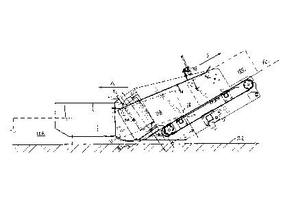
thereby held on the
chain, so that the bale is then moved along the conveyor. However, the teeth
can damage the
bale somewhat when inserted, and/or when removed.
[0004] As is well known in the art, it is advantageous to pick up the
bales when the
machine is moving, e.g., the machine may travel at a speed of about 8 lcm/lu.
to about 15 km/hr,
picking up bales without stopping. However, with the pick-up devices of the
prior art, the bale is
sometimes not picked up quickly, and the bale is then pushed along the ground
by the pick-up
1
CA 02714249 2010-09-07
device for a distance before the bale is picked up. This delay in picking up
the bale results in dirt
becoming embedded in the bale, thereby causing potentially significant
problems.
SUMMARY OF THE INVENTION
[0005] For the foregoing reasons, there is a need for an improved bale
pick-up assembly
which overcomes or mitigates one or more of the defects of the prior art.
[0006] In its broad aspect, the invention provides a pick-up assembly for
moving an
object off a surface. The pick-up assembly includes a conveyor subassembly
extending between
lower and upper ends thereof. The conveyor subassembly includes a conveying
means extending
between the lower and upper ends, for moving the object to the upper end. The
pick-up
assembly also includes two or more engagement devices positioned proximal to
the lower end of
the conveyor subassembly for engaging opposite sides of the object
respectively, to move the
object onto the conveying means.
[0007] In another aspect, the engagement devices lift the object at least
partially over the
lower end as the object is moved thereby onto the conveying means.
[0008] In another aspect of the invention, each of the engagement devices
is rotatable
about an engagement device axis therefor.
[0009] In yet another aspect, the conveying means is an endless conveyor
belt, and the
conveyor subassembly additionally includes lower and upper conveyor rollers
positioned
substantially at the lower and upper ends respectively, for engaging the
conveyor belt.
[0010] In another aspect, the lower and upper conveyor rollers (and/or
the lower and
upper ends) define one or more conveyor planes therebetween.
[0011] In one aspect of the invention, each engagement device axis is
positioned at a
preselected angle therefor relative to the conveyor plane, for lifting the
object at least partially
over the lower end of the conveyor subassembly as the object is moved onto the
conveyor belt.
2
CA 02714249 2010-09-07
[0012] In another aspect, each of the engagement devices is a roller.
[0013] In yet another aspect, each roller is mounted in a bracket movable
between an
inner position, in which the roller is located proximal to the lower end of
the conveyor
subassembly, and an outer position, in which the roller is located distal to
the lower end of the
conveyor subassembly.
[0014] In another aspect, each bracket is at least partially supported by
a stop element
therefor.
[0015] In another of its aspects, the invention additionally provides a
control bar
subassembly, for pressing the bale onto the conveyor belt.
[0016] In one aspect of the invention, the control bar subassembly
includes a control bar
extending between a front end and a back end thereof, a control bar bracket in
which the front
end of the control bar is pivotably mounted, and a spring means engageable
with the control bar,
for urging the control bar toward the conveyor belt, for pressing each said
bale onto the conveyor
belt.
[0017] In another of its aspects, the invention additionally provides a
floatation
suspension, for maintaining the conveyor subassembly in a substantially
consistent position
relative to the surface.
[0018] In yet another aspect, the floatation suspension includes a spring
support means
pivotably connected to the conveyor subassembly, for urging the conveyor
subassembly to a
predetermined position relative to the surface, and a hydraulic cylinder,
pivotably connected to
the conveyor subassembly, for urging the conveyor subassembly to the
predetermined position.
The flotation suspension also includes a linkage bracket pivotably connected
to the conveyor
subassembly and extending between first and second ends thereof, the linkage
bracket being
pivotably connected to the conveyor subassembly at the first end thereof. The
hydraulic cylinder
means are pivotably connected to the linkage bracket at the second end. The
spring support
3
CA 02714249 2010-09-07
means and the hydraulic cylinder means urge the conveyor subassembly to the
predetermined
position relative to the surface.
BRIEF DESCRIPTION OF THE DRAWINGS
[0019] The invention will be better understood with reference to the
attached drawings,
in which:
[0020] Fig. 1A (previously described) is an isometric view of a typical
bale;
[0021] Fig. 1B is an isometric view of an embodiment of a pick-up
assembly of the
invention, drawn at a smaller scale;
[0022] Fig. 2 is a front view of the pick-up assembly of Fig. 1B, drawn
at a smaller scale;
[0023] Fig. 3 is a top view of the pick-up assembly of Fig. 1B;
[0024] Fig. 4 is a first side view of the pick-up assembly of Fig. 1B,
drawn at a larger
scale;
[0025] Fig. 5A is a cross-section of the pick-up assembly of Fig. 1B,
showing bales at
certain positions thereon;
[0026] Fig. 5B is the cross-section of Fig. 5A, showing the bales of Fig.
5A at positions
subsequent to those illustrated in Fig. 5A;
[0027] Fig. 6 is a second side view of the pick-up assembly of Fig. 1B,
with a part of the
body cut away to show a part of a floatation suspension;
[0028] Fig. 7 is another view of the pick-up assembly of Fig. 6, showing
the flotation
suspension in a different position;
4
CA 02714249 2010-09-07
[0029] Fig. 8A is a top view orthogonal to top ends of the rollers in the
pick-up assembly
of Fig. 1B;
[0030] Fig. 8B is an isometric view of an embodiment of a bracket of the
invention,
drawn at a larger scale;
[0031] Fig. 8C is another isometric view of the bracket of Fig. 8B;
[0032] Fig. 9 is an isometric view of an embodiment of a conveyor roller
of the
invention, drawn at a larger scale;
[0033] Fig. 10 is an end view of the conveyor roller of Fig. 9; and
[0034] Fig. 11 is a top view of a machine with the pick-up assembly of
Fig. 1B mounted
thereon, drawn at a smaller scale.
DETAILED DESCRIPTION
[0035] In the attached drawings, like reference numerals designate
corresponding
elements throughout. Reference is first made to Figs. 1B-10 to describe an
embodiment of a
pick-up assembly of the invention referred to generally by the numeral 20. The
pick-up
assembly 20 is for moving the object 10 (e.g., a bale) off a surface 22 (Figs.
5A-7). In one
embodiment, the pick-up assembly 20 includes a conveyor subassembly 24
extending between
lower and upper ends thereof 26, 28. Preferably, the conveyor subassembly 24
includes a
conveying means 34 extending between the lower and upper ends 26, 28
respectively, for
moving the object to the upper end 28. The pick-up assembly 20 preferably also
includes two or
more engagement devices 42, 44 (Figs. 1B-3) positioned proximal to the lower
end 26 of the
conveyor subassembly 24 for engaging opposite sidewalls 5 1 , S2 of the object
10 respectively
(Fig. 3), to move the object 10 onto the conveyor means 34, as will be
described.
[0036] Preferably, the engagement devices 42, 44 lift the object at least
partially over the
lower end 26 as the object 10 is moved thereby onto the conveying means 34.
CA 02714249 2010-09-07
,
[0037] As will also be described, in one embodiment, each of the
engagement devices 42,
44 preferably is rotatable about an engagement device axis "X" therefor. The
engagement device
axes for the engagement devices 42, 44 are designated "Xl" and "X2"
respectively for
convenience, as can be seen in Figs. 1B and 4-6.
[0038] Those skilled in the art will appreciate that the conveying
means may be any
suitable means for conveying the objects (i.e., bales) to the upper end 28 of
the conveyor
subassembly 24. In one embodiment, the conveying means 34 preferably is an
endless conveyor
belt, and the conveyor subassembly 24 preferably includes lower and upper
conveyor rollers 30,
32 positioned substantially at the lower and upper ends 26, 28 respectively,
for engaging the
conveyor belt 34.
[0039] As can be seen in Fig. 5, the lower and upper conveyor rollers
30, 32 preferably
define one or more conveyor planes 40 therebetween. It will be appreciated
that the lower and
upper ends 26, 28 also define the conveyor plane 40. The conveyor plane 40
preferably is
substantially parallel to an upper surface 67 of the conveying means 34, the
upper surface 67
extending between the lower and upper ends 26, 28 of the conveyor subassembly
24.
[0040] It is also preferred that each engagement device axis 42, 44
is positioned at a
preselected angle 0 therefor relative to the conveyor plane 40, for lifting
the object 10 at least
partially over the lower end 26 of the conveyor subassembly 24 as the object
10 is moved onto
the conveyor belt 34. In practice, to accomplish the lifting movement, the
preselected angle 0
preferably is at least slightly obtuse. Preferably, the preselected angle 0 is
between
approximately 90.5 and approximately 105 . In one embodiment, each of the
engagement
devices 33 preferably is a roller.
[0041] It will be understood that the pick-up assembly 20 is mounted
on a machine 46
(Fig. 11). Preferably, the machine 46 is any machine for holding and/or
processing the objects
which are moved off the surface 22. The pick-up assembly 20 preferably is
attached to the
machine 46 with the upper end 28 proximal to the machine 46. When the bale is
moved to the
upper end 28, the bale then exits the pick-up assembly 20 to fall onto or
otherwise is placed in or
on the machine 46.
6
CA 02714249 2010-09-07
[0042] In particular, and as will be described, the pick-up assembly 20 is
adapted to
engage and move the bales 10 discretely (i.e., serially) while the machine 46,
and the pick-up
assembly 20 mounted thereon, are travelling relative to the surface 22 in the
direction indicated
by arrow "A" (Figs. 3, 5A-6). For instance, the machine 46 (and the pick-up
assembly 20
mounted thereon) may travel in the direction indicated by arrow A at between
about 8 km/hr.
(about 5 mph) and about 15 km/hr. (about 9 mph).
[0043] Those skilled in the art will appreciate that any suitable
source(s) of power may
be used to rotate the engagement devices 42, 44 and/or to move the conveyor
belt 34. However,
in one embodiment, the pick-up assembly 20 preferably is powered by a single
power source (not
shown) which, via drive systems 48, 48' (Figs. 4, 6), transfers power created
thereby to the
conveyor rollers (i.e., to move the conveyor belt 34), and to the rollers 42,
44. For example, in
one embodiment, the power source preferably is a hydraulic motor (not shown)
with a first
sprocket 50 directly secured thereto, rotated by the hydraulic motor (Fig. 4).
[0044] Those skilled in the art will appreciate that any suitable drive
system may be used.
Preferably, each of the drive systems is a combination chain-and-belt drive
system. As can be
seen in Fig. 4, the first sprocket 50 preferably is connected by a first chain
or other suitable
power transmission means 52 to a first conveyor sprocket 54, so that the upper
conveyor roller
32 is rotated when the first sprocket 50 is rotated. (The first conveyor
sprocket 54 is coaxial with
and secured to the upper conveyor roller 32.) Also, the first sprocket 50
preferably is connected
to a second sprocket 56 via a second chain (or other suitable power
transmission means) 58.
Preferably, a first pulley 60 (Fig. 3) is coaxial with and secured to the
second sprocket 56, so that
the first pulley 60 rotates with the second sprocket 56.
[0045] A second pulley 62 preferably is mounted on a shaft 64 coaxial with
the
engagement device axis Xi (Fig. 1B). As can be seen in Figs. 1B and 4, the
first pulley 60 and
the second pulley 62 are connected by a V belt 64. However, those skilled in
the art would
appreciate that any suitable means for power transmission may be used to
connect the pulleys.
Due to the connection of the second pulley 62 and the first pulley 60 via the
V belt 64, rotation
of the second sprocket 56 results in rotation of the roller 42 about the axis
X1 therefor, as will be
described.
7
CA 02714249 2010-09-07
[0046] The drive system 48 preferably also includes tensioning sprockets
66A, 66B for
adjusting the tension of the first and second chains 52, 58 from time to time,
as is known in the
art.
[0047] It will be appreciated by those skilled in the art that, as
illustrated in Fig. 4, when
the first sprocket 50 is rotated in a clockwise direction (as indicated by
arrow "C" in Fig. 4), the
first conveyor sprocket 54 also rotates in a clockwise direction, as indicated
by arrow "D" in Fig.
4. This results in clockwise rotation of the upper conveyor roller 32, and
consequent movement
of the conveyor belt 34 so that the object 10, when positioned on the upper
surface 67 (Figs. 5A,
5B) is moved from the lower end 26 to the upper end 28, i.e., in the direction
indicated by arrow
"G" in Figs. 5A and 5B. Also, because the conveyor belt 34 is under tension
and is stretched
between the lower and upper conveyor rollers 30, 32, the movement of the
conveyor belt 34 due
to rotation of the upper conveyor roller 32 results in rotation of the lower
conveyor roller 30 in
the same direction. Similarly, and at the same time, the second sprocket 56 is
also rotated in a
clockwise direction (as illustrated in Fig. 4), as indicated by arrow "E" in
Fig. 4. As noted
above, via the V belt 64, this rotation ultimately causes the roller 42 to
rotate about the
engagement device axis Xi in the direction indicated by arrow "F1", as shown
in Figs. 3 and 8A.
(The engagement device axes for the rollers 42 and 44 are identified as Xi and
X2 respectively in
Figs. 1B, 3, 4, 5A, and 5B for clarity.)
[0048] It will be appreciated by those skilled in the art that, as can be
seen in Fig. 6, the
roller 44 preferably is driven by a second drive system 48'. Although those
skilled in the art
would appreciate that many different arrangements are possible, in one
embodiment (hereinafter
described), it is preferred that only one hydraulic motor drives the conveyor
belt and both rollers
42, 44. The second drive system 48' includes a second conveyor sprocket 54'
which is mounted
to (and coaxial with) the upper conveyor roller 32. It will be understood that
rotation of the
upper conveyor roller 32 in the clockwise direction (as illustrated in Fig. 4)
is illustrated in Fig. 6
as rotation of the upper conveyor roller 32 in a counterclockwise direction.
[0049] As can be seen in Fig. 6, when the upper conveyor roller 32 is
rotated in a
counterclockwise direction (as indicated by arrow "Du' in Fig. 6), the second
conveyor sprocket
54' is also rotated counterclockwise. The second conveyor sprocket 54' and a
second sprocket
8
CA 02714249 2010-09-07
56' are connected by a chain or other suitable power transmission means 59,
and
counterclockwise rotation of the second sprocket 56' as indicated by arrow "E"
in Fig. 6)
therefore results from counterclockwise rotation of the second conveyor
sprocket 54'. In turn,
such rotation of the second sprocket 56' results in rotation of a first pulley
60' (Fig. 3) coaxial
therewith. The first pulley 60' and the second pulley 62' are connected by a V
belt 64', so that
counterclockwise rotation of the first pulley causes rotation of the roller 44
about its axis,
designated as X2. (In Fig. 3, the V belt 64' is omitted so that the pulley 60'
may be clearly
shown.)
[0050] By way of example, three bales identified for convenience as 10A-
10C
respectively are shown in Fig. 3. As illustrated in Fig. 3, the bale 10A has
not yet been engaged
by the rollers 42, 44, but is generally aligned with the conveyor belt 34. In
Figs. 3 and 5A, the
bale 10B is shown as when first engaged by the rollers 42, 44, which are
moving the bale 10B
onto the conveyor belt 34. Also in Figs. 3 and 5A, the bale 10C is shown
shortly after it has been
positioned on the conveyor belt 34. The bale 10C is moved upwardly by the
conveyor belt 34 at
an angle, i.e., in the direction indicated by arrow "G" in Fig. 5A.
[0051] The bale 10B is shown in Fig. 5A shortly after it has been engaged
by the rollers
42, 44. As can be seen in Fig. 5A, due to the rollers' axes X1, X2 being at
the preselected angle 0
relative to the conveyor plane 40, after the bale 10B is first engaged by the
rollers 42, 44, a
leading end 68 of the bale 10B is lifted above a trailing end 70 thereof,
i.e., the leading end 68 is
raised, so that the bale 10B is tilted upwardly. As can be seen in Fig. 5A,
the leading end 68
preferably is lifted over the lower end 26 of the conveyor subassembly 24, as
the bale 10B is also
moved generally upwardly (i.e., in the direction indicated by arrow "B" in
Fig. 5A).
Accordingly, each bale's leading end is lifted over the lower end 26 of the
conveyor subassembly
24, thereby minimizing the risk that any bale may be pushed along the ground
surface, and also
minimizing the risk of damage to the bale. As will be described, as the bale
is lifted over the
lower end of the conveyor subassembly, it is also propelled onto the conveyor
belt 34 by the
rollers 42, 44.
9
CA 02714249 2010-09-07
[0052] In Fig. 5B, the bales 10A-10C are shown positioned relative to the
conveyor
subassembly 24 a few seconds after the situation illustrated in Fig. 5A. As
shown in Fig. 5B, at
this point, the bale 10B is still engaged by the rollers 42, 44. The leading
edge 68 of the bale
10B engages the conveyor belt 34 at a point 71 (Fig. 58). It will be apparent
that, when the bale
10B is in the position shown in Fig. 5B, the conveyor belt 34 engages the
leading edge 68 of the
bale 10B (i.e., pulling the bale 10B upwardly along the conveyor plane 40),
and the rollers 42, 44
remain engaged with the bale 10B also, to push the bale 10B generally
upwardly, in a direction
generally up the conveyor plane 40.
[0053] The point 71 at which the leading edge 68 engages the conveyor
belt 34 is a
distance "L" sufficiently distant from the lower end 26 of the conveyor
subassembly 22 that the
bale 10B is unlikely to fall off the conveyor belt 34 and be pushed along on
the surface 22 by the
lower end 26 of the conveyor subassembly 24. For example, it has been found
that the assembly
works well if the distance L is at least approximately 10 inches.
[0054] From Figs. 5A and 5B, it can be seen that, when the bale 10B has
moved past the
rollers 42, 44 and is thereby released, a sufficient proportion of the bottom
surface of the bale
10B engages the conveyor belt 34 that the bale 10B does not fall down, off the
conveyor belt 34,
but is instead engaged by the conveyor belt 34 and carried thereby to the
upper end 28, at which
the bale 10B is discharged from the conveyor subassembly 24.
[0055] Preferably, the rollers 42, 44 are made of, and covered with, any
suitable
material(s). In one embodiment, the rollers 42, 44 are hollow steel cylinders
approximately 8
inches in diameter and approximately 14 inches long. Also, the rollers 42, 44
preferably have a
relatively soft rubber or plastic coating (e.g., the product known as "rough
top pulley lagging")
on engagement surfaces 43, 45 thereof respectively (Figs. 4, 6) for gripping
the bales, with
minimal damage to the bales. However, those skilled in the art will appreciate
that the rollers 42,
44 may have any suitable shape, whether regular or irregular, and may be made
of any suitable
material(s).
[0056] In one embodiment, and as can be seen in Fig. 8A, each roller 42,
44 is mounted
in a bracket 72, 72' respectively movable between an inner position, in which
each roller 42, 44
CA 02714249 2010-09-07
is located proximal to the lower end 26 of the conveyor subassembly 24, and an
outer position, in
which each roller 42, 44 is located distal to the lower end 26 of the conveyor
subassembly 24
(Fig. 8A). Preferably, each bracket 72, 72' is biased to the inner position
therefor. It is preferred
that each bracket 72, 72' is biased to the inner position by one or more
resilient biasing means 73,
73' respectively. It will be understood that the rollers 42, 44, the brackets
72, 72' and the resilient
biasing means 73, 73' are shown in Fig. 8A in solid outline in the inner
position and in chain-
dotted outline in the outer position, for clarity of illustration.
[0057] For clarity, the brackets for the rollers 42, 44 are identified in
Figs. 3 and 8A as 72
and 72' respectively. In the following description, only the bracket 72 is
described in detail, for
convenience. It will be understood that the brackets 72, 72' are mirror images
of each other, and
do not differ materially.
[0058] As can be seen in Figs. 1B and 8A, in one embodiment, the bracket
72 preferably
includes a mounting portion 74 in which the roller 42 is rotatably mounted,
and upper and lower
arms 76, 78 (Figs. 8B, 8C) extending between first and second ends 81, 82, and
83, 84
respectively thereof. Preferably, the first ends 81, 82 of the upper and lower
arms 76, 78
respectively are secured to the mounting portion 74 by any suitable means,
e.g., welding. It is
also preferred that the second ends 83, 84 are pivotably mounted on a wall
portion 75A of the
pick-up assembly 20, so that the bracket 72 pivots about a pivot point "P".
[0059] As can be seen in Figs. 1B-3, the pick-up assembly 20 preferably
includes wall
portions 75A, 75B positioned on opposite sides of the conveyor subassembly 24.
Preferably, the
resilient biasing means 73 includes one or more springs extending between the
wall portion 75A
and the bracket 72. Pins are mounted in tabs (not shown) to position pivot
points "P"
appropriately, as is known in the art. It is preferred that each resilient
biasing means 73 is a
spring. As can be seen in Fig. 1B, each spring 73 may be connected to the
lower arm 78 of the
bracket 72.
[0060] For clarity of illustration, only one spring 73 is shown. The
springs 73 bias the
bracket 72 to the inner position. The springs 72 also serve to subject the V
belt 64 to tension.
11
CA 02714249 2010-09-07
[0061] As can be seen in Figs. 2, 3, and 8A, when the brackets 72, 72' are
in the inner
position, the rollers 42, 44 are in position to engage each bale 10 as the
pick-up assembly 20 is
moved toward the bale 10. Preferably, the rollers 42, 44 are about 17 inches
apart, when in the
inner position. (This positioning has been found to work well when the bales
are about 18 inches
wide.) However, it will be understood that the locations of the brackets 72,
72' in Fig. 8A in the
outer position are exaggerated, for the purposes of clarity in the
illustration. Preferably, each of
the brackets 72, 72' is movable between the inner and outer positions in order
that the pick-up
assembly 20 may pick up each bale 10 consistently, regardless of whether the
bales 10 are not
properly oriented relative to the conveyor belt 34, or whether, e.g., some
bales are relatively
small or otherwise deviate from the standard dimensions for a bale.
[0062] As can be seen in Fig. 3, when the brackets 72, 72' are in the
inner position, the
engagement devices 42, 44 preferably compress the bale slightly, squeezing the
sidewalls S1, S2.
(It will be understood that the sidewalls SI, S2 are not shown as being
compressed in Fig. 3 for
clarity of illustration.)
[0063] Preferably, each bracket 72, 72' is substantially rigid. Those
skilled in the art will
appreciate that the bracket 72, 72' may be made of any suitable materials.
Preferably, the bracket
72, 72' is made of a suitable steel.
[0064] In one embodiment, each bracket 72 is at least partially supported
by a stop
element 86 therefor. As can be seen in Figs. 1B and 8A, the stop element 86
preferably is a
substantially flat member, cantilevered from the wall portion 75A, to support
the bracket 72 (and
the roller 42) in position. Because of the stop element 86, the bracket 72 is
maintained in
position relative to the conveyor subassembly 26, i.e., so that the axis X1
substantially defines the
predetermined angle 0 relative to the conveyor plane 40.
[0065] Preferably, each bracket 72 slidably engages the stop element 86
therefor as each
bracket 72 moves between the inner and outer positions (Fig. 8A). The lower
arm 78 slidingly
engages the stop element 86. It is preferred that a suitable lubricant (not
shown) is positioned on
the stop element 86, to facilitate the sliding engagement of the lower arm 78
with the stop
element 86.
12
CA 02714249 2010-09-07
[0066] It will be understood that the outer position, as illustrated in
Fig. 8A, is further out
from the conveyor than is practical. The outer position has been exaggerated
in this regard in
Fig. 8A, for clarity of illustration. The bracket 72 preferably is supported
by the stop element 86
as the bracket 72 moves between the inner and outer positions.
[0067] In one embodiment, the pick-up assembly additionally includes a
control bar
subassembly 88 (Figs. 1B-3), for pressing the bale 10 onto the conveyor belt
34. Preferably, the
control bar subassembly 88 includes a control bar 90 extending between a front
end 92 and a
back end 94 thereof, and a control bar bracket 96 in which the front end 92 of
the control bar 90
is pivotably mounted (Figs. 3, 5A, 5B). It is also preferred that the control
bar subassembly 88
includes a spring means 98 engageable with the control bar 90, for urging the
control bar 90
toward the conveyor belt 34, to press each bale 10 onto the conveyor belt 34
as each bale passes
underneath the control bar 90.
[0068] As can be seen in Figs. 5A and 5B, the control bar 90 is urged
generally
downwardly (i.e., in the direction indicated by arrow "J" in Figs. 5A and 5B)
by the spring
means 98. As noted above, the front end 92 of the control bar 90 is pivotably
mounted to the
control bar bracket 96. The control bar 90, because the back end 94 thereof is
urged downwardly
by the spring means 98, presses each bale 10 passing under the control bar 90
onto the conveyor
belt 34, which causes positive engagement of each bale 10 with the conveyor
belt 34, to
substantially prevent slippage of the bale 10 relative to the conveyor belt
34, once the bale 10 is
located on the conveyor belt 34.
[0069] As can be seen, for instance, in Figs. 3 and 8A, the assembly 20
preferably
includes panels 99A, 99B mounted on the wall portions 75A, 75B respectively.
The panels 99A,
99B are intended to "funnel" (or guide) bales 10 to the conveyor belt 34 as
the pick-up assembly
20 is moved forward. As can be seen, for example, in Fig. 3, the panels 99A,
99B preferably are
mounted on the wall portions 75A, 75B so as to define any suitable angle
therebetween. For
example, it has been found that the angle between the panels 99A, 998 and the
wall portions
75A, 75B respectively may be approximately 160 .
13
CA 02714249 2010-09-07
[0070] As can be seen in Fig. 1B, the pick-up assembly 20 preferably
includes a cover
105 for each side of the assembly 20, for covering the drive systems 48, 48',
the chains and V
belts mounted therein, the brackets 72, 72' and, to an extent, the rollers 42,
44. Although the
cover 105 is shown mounted on only one side of the pick-up assembly 20, it
will be understood
that the cover 105 is mounted on both sides of the assembly 20. The cover 105
is omitted from
the drawings generally, for clarity of illustration.
[0071] As can be seen in Figs. 2 and 3, each of the wall portions 75A, 75B
preferably
includes a top flange 107A, 107B respectively, to provide a transverse surface
to which various
elements may be mounted. It will be understood that a part of the top flange
107A is omitted
from Fig. 3 for clarity of illustration, i.e., in order that the pulley 60 and
part of the V belt 64 may
be clearly shown. Those skilled in the art will appreciate that the pick-up
assembly 20
additionally includes a number of structural elements which are generally not
shown, e.g.,
structural elements connecting the wall portions 75A, 75B. Because such
elements and the
details of construction regarding same are well known in the art, it is not
necessary to describe
them in detail.
[0072] In use, the pick-up assembly 20 preferably is mounted on the
machine or vehicle
46 (Figs. 6, 7, 11). As can be seen in Figs. 6 and 7, the pick-up assembly 20
preferably is
mounted to the machine 46 via conventional means. The hydraulic motor (not
shown) powering
the conveyor subassembly 24 and the rollers 42, 44 preferably is itself
activated by appropriate
means therefor (not shown) mounted on the machine 46. For instance, in one
embodiment, the
hydraulic motor in the assembly 20 is connected in series with a second
hydraulic motor in the
machine 46, as is known in the art. Once the hydraulic motor in the assembly
20 has been
operably connected to the means for activation therefor, the machine 46 (with
the assembly
mounted thereon) is ready to travel in the direction indicated by arrow A
(Fig. 11). While the
machine 46 and the pick-up assembly 20 are travelling forwardly (i.e., in the
direction indicated
by arrow A), the motor preferably is energized, causing the conveyor roller 32
to rotate (thereby
moving the conveyor belt 34), and also causing the rollers 42, 44 to rotate
about the axes Xi, X2
respectively, as described above, so that the bales are picked up while the
machine 46 is moving.
14
CA 02714249 2010-09-07
[0073] As shown in Figs. 3, 5A, and 5B, as the bales 10 are encountered
while the
machine 46 and the assembly 20 move forward, the panels 99A, 99B guide the
bales 10 toward
the rollers 42, 44 and the conveyor belt 34. When the rollers 42, 44 are
brought into contact with
each bale (i.e., as the rollers are rotating), the rollers 42, 44 rapidly
engage the sides of the bale
and, at least initially, lift it substantially in a direction orthogonal to
the axes Xi, X2 of
rotation. The leading end 68 of the bale 10 is lifted over the lower end 26 of
the conveyor
subassembly 24, and the leading end 68 is engaged by the conveyor belt 34 at a
distance "L" up
the conveyor belt 34 from the lower conveyor roller 30. At that point, the
bale 10 is pulled up
the conveyor plane 40 by the conveyor belt 34, and is simultaneously pushed
generally upwardly
by the rollers 42, 44. When the trailing end 70 of the bale 10 passes between
the rollers 42, 44,
most of the bale 10 is positioned sufficiently far up the conveyor plane 40
that there is little risk
of the bale 10 falling off the conveyor belt 34 at the lower end 26. As the
bale 10 is moved onto
the conveyor belt 34, the control bar subassembly 88 gently presses the bale
10 (to the extent it is
positioned between the control bar 90 and the conveyor belt 34) onto the
conveyor belt 34, to
engage the bale 10 with the conveyor belt 34.
[0074] In another embodiment, as can be seen in Figs. 6 and 7, the pick-
up assembly 20
of the invention preferably includes a floatation suspension 121, for
maintaining the conveyor
subassembly 24 in a substantially consistent preselected position relative to
the surface 22. (In
Figs. 6 and 7, part of the wall portion 75B is omitted to show parts of the
floatation suspension,
i.e., for clarity of illustration.) As can be seen in Figs. 6 and 7, the
floatation suspension 121 is
movable between a base condition (Fig. 6) and an extended condition (Fig. 7).
In Fig. 7, the
floatation suspension 121 is shown after the machine 46 on which the pick-up
assembly 20 is
mounted has encountered a significant bump in the surface 22. The preselected
position of the
conveyor subassembly is shown in Fig. 6, i.e., when the floatation suspension
121 is in the base
condition, the conveyor subassembly 24 is in the preselected position. As can
be seen Fig. 6,
when the conveyor subassembly 24 is in this position, the pick-up assembly 20
is positioned to
pick up bales.
CA 02714249 2010-09-07
[0075] As can be seen in Figs. 6 and 7, the floatation suspension 121
preferably includes
a spring support means 123 pivotably connected to the conveyor subassembly 24,
for urging the
conveyor subassembly 24 to the preselected position relative to the surface
22.
[0076] In one embodiment, the flotation suspension 121 preferably also
includes a
hydraulic cylinder 125, pivotably connected to the conveyor subassembly 24,
for urging the
conveyor subassembly 24 to the preselected position, and a linkage bracket 127
pivotably
connected to the conveyor subassembly 24 and extending between first and
second ends 129,
131 thereof, the linkage bracket 127 being pivotably connected to the conveyor
subassembly 24
at the first end 129 thereof.
[0077] The hydraulic cylinder 125 preferably is pivotably connected to
the linkage
bracket 127 at the second end 131. The spring support means 123 and the
hydraulic cylinder 125
urge the conveyor subassembly 24 to the preselected position relative to the
surface 22. As can
be seen in Fig. 5A, the conveyor subassembly 24 preferably is positioned at an
angle a relative to
the surface 22. The angle a may be any suitable angle. Preferably, the angle a
is about 30 .
[0078] Preferably, each of the spring support means 123 and the hydraulic
cylinder 125
are pivotably mounted to the machine 46, thereby providing resilient linkages
between the pick-
up assembly 20 and the machine 46, so that the conveyor subassembly 24 is
generally returned to
the preselected positions after it has been subjected to bouncing and bumping.
[0079] It will be understood that the position of the conveyor
subassembly 24 relative to
the machine 46 as illustrated in Fig. 7 is exaggerated, for clarity of
illustration. In Fig. 7, the
pick-up assembly 20 is shown after the conveyor subassembly 24 has been
pivoted upwardly
(i.e., in the direction indicated by arrow "K1"), e.g., after the machine 46
(and/or the pick-up
assembly 20) has encountered a bump in the surface 22 while travelling
forward. It will be
appreciated by those skilled in the art that the floatation suspension 121
both dampens the
downward movement and also allows the conveyor subassembly 24 to return to the
base
condition, i.e., in the direction indicated by arrow "K2" in Fig. 7.
16
CA 02714249 2016-07-13
[0080] It will be appreciated by those skilled in the art that the pick-
up assembly 20
preferably should extend from the front of the machine 46 on which it is
mounted to a minimal
extent, i.e., the overall length of the machine 46 and the pick-up assembly 20
combined
preferably is minimized, to the extent feasible. In turn, this means that the
conveyor plane 40
preferably should be positioned at the steepest angle which is feasible. In
practice, it has been
determined that the steepest feasible angle is about 300
.
[0081] Preferably, each of the conveyor rollers 30, 32 includes a
framework of ribs 135
spaced apart to permit material (not shown) to flow therethrough. Preferably,
the ribs 135 are
formed to direct the material out of the conveyor roller 30, 32 as the
conveyor roller 30, 32
rotates. For example, in practice, small pieces of hay may fall into the part
of the conveyor
where the conveyor rollers 30, 32 are located. Such material tends to be swept
away by the ribs
135 which are arranged to do so.
[0082] In one embodiment, each conveyor roller includes end portions
137A, 137B and a
central support element 139 mounted on an axle 141. The ribs 135 preferably
extend between
the end portions 137A, 137B, and are supported by the central support element
139. It will be
understood that the conveyor sprockets 54, 54' are coaxially mounted on the
opposite ends of the
axle 141.
[0083] It will be appreciated by those skilled in the art that the
invention can take many
forms, and that such forms are within the scope of the invention as claimed.
The scope of the
claims should not be limited by the preferred embodiments set forth in the
examples, but should
be given the broadest interpretation consistent with the description as a
whole.
17