Note : Les descriptions sont présentées dans la langue officielle dans laquelle elles ont été soumises.
CA 02714548 2010-07-29
WO 2009/094715 PCT/AU2009/000102
- 1 -
DEVICE FOR IMPROVED METHOD OF BLASTING
The present invention relates to a cartridge that contains an explosive
composition and that
is adapted to achieve deactivation of the explosive composition in the event
that it is not
detonated as intended during use.
Explosives are used in a significant number of commercial applications, such
as mining,
quarrying and seismic exploration. In mining and quarrying a detonator is
typically used
to initiate a cartridged primer charge that in turn detonates bulk explosive.
In seismic
exploration a relatively small cartridged explosive charge is initiated using
a detonator and
the shock waves that are generated are monitored and analysed.
When a charge fails to detonate as intended there are obvious safety and
security issues. In
that event, it may be possible to recover the charge, although this is not
always possible for
a variety of reasons. For example, in seismic exploration where charges or
trains of
charges are positioned and detonated, recovery of undetonated charges can be
difficult,
especially when the charge(s) is/are positioned in an underground borehole and
the
borehole has been backfilled, as is common practice. There are therefore
instances where
undetonated charges remain unrecovered in the field. In such cases, and as a
general point,
it would therefore be desirable to render safe any undetonated and unrecovered
explosive
charges. A variety of approaches to address this need already exist.
By way of example, US 3,948,177, describes an explosive cartridge for
underwater
blasting which is said to be self-disarming in the event of an underwater
misfire. The
cartridge comprises a closed shell including an internal conduit. Water
external to the
cartridge is prevented from flowing into the conduit by a watertight seal. The
force of a
percussion impact initiation can however break the watertight seal thereby
allowing water
to flow into the conduit and contact with explosive composition contained. In
turn, water
can dissolve the (nitrocarbonate) explosive possibly also causing it to flow
out of the body
of the cartridge. The result is desensitisation. Whilst generally useful, a
problem with this
approach is that desensitisation is contingent upon some form of specific
force associated
CA 02714548 2010-07-29
PCT/AU2009/000102
`P \OPERUCC \SPECIFICATIONS \thical2073 \ 30725483 PCT amended clanns July
09.doc-3/08/2009
Received 4 August 2009
= - 2 -
=
with a misfire to break the watertight seal. If there is no applied force
resulting from a misfire,
the cartridge would not be disarmed by the action of water.
The present invention seeks to provide an alternative approach to rendering
safe explosive
compositions that does not suffer the disadvantages described above.
Accordingly, in one embodiment, the present invention provides an explosive
cartridge
comprising: an explosive composition; a deactivating agent that is capable of
desensitising the
explosive composition; and a barrier element that prevents contact between the
explosive
composition and the deactivating agent, wherein the cartridge is adapted to
allow water to
enter, or be delivered into, the cartridge so that the water will come into
contact with the
deactivating agent, wherein the deactivating agent is provided in a form that
is rendered mobile
by water that enters or is delivered into the cartridge when used, wherein the
barrier element is
adapted to be breached or at least partially removed when the deactivating
agent is rendered
mobile in that way so that the deactivating agent comes into .contact with the
explosive
composition, and wherein when mobile the deactivating agent renders the
explosive
composition insensitive to detonation after a predetermined period of time.
In another embodiment the present invention provides an explosive cartridge
comprising: an
explosive composition; a deactivating agent that is capable of desensitising
the explosive
composition; and a barrier element that prevents contact between the explosive
composition
and the deactivating agent and that is adapted to be at least partially
removed on use of the
explosive cartridge, wherein the barrier element takes the form of flexible
membrane attached
to a support member, the support member being resiliently extendable between a
retracted
position in which the flexible membrane does not prevent contact between the
deactivating
agent and the explosive composition and an extended position in which the
flexible membrane
prevents contact between the deactivating agent and the explosive composition,
one end of the =
support member being attached to an internal wall of the explosive cartridge
and the other end
= of the support member being attached in the extended position to a
release mechanism,
wherein the release mechanism prevents movement of the support member between
extended
and retracted positions for a predetermined period of time.
In another embodiment the present invention provides and explosive cartridge
comprising: an
explosive composition; a deactivating agent that is capable of desensitising
the explosive
= Amended Sheet
IPEAJAU
CA 02714548 2010-07-29
=
awroaannccuinuonnr_ispC-ImArAnin PCT/AU2009/00000102
Received 13 January 2010
-2A -
composition; and a barrier element that prevents contact between the explosive
composition ,
and the deactivating agent and that is adapted to be at least partially
removed on use of the
explosive cartridge after a predetermined period of time, wherein the
deactivating agent is in
liquid form and wherein when the barrier element is at least partially removed
the deactivating
5 agent is released into a chamber comprising a wall that is in intimate
contact with the explosive
composition and that is made of a material that is porous to, or that is
degraded by, the
deaotivating agent or component thereof, and wherein the chamber has branches
extending
= throughout the explosive composition to provide in use intimate contact
between the
deactivating agent and the explosive Composition.
to =
In yet another embodiment the present invention provides an explosive
cartridge comprising:
an outer shell; an explosive composition surrounded by the outer shell; a
deactivating agent
that is distributed throughout the explosive composition in the form of
granules or pellets and
that is capable of desensitising the explosive composition after a
predetermined period of time
15 when the pellets or granules are contacted with water thereby rendering
the deactivating agent
= mobile, and wherein the outer shell includes passages =that extend into
the explosive
composition and that are made of water-permeable or water degradable material.
In accordance with the present invention, the action of a deactivating agent
on the explosive
20 composition is responsible for rendering the explosive composition
insensitive to detonation,
i.e. safe. Herein, unless otherwise evident, when it is indicated that an
explosive composition
is rendered insensitive t' detonation means that the explosive composition
has, by action of the
= deactivating agent, been desensitised at least to the extent that the
normal (predetermined)
method of initiation of the explosive composition is no longer effective.
Thus, for an
25 explosive composition that is known to. be detonated using a particular
type of initiating
device, in accordance with the present invention the explosive charge is i-
endered insensitive to
= detonation if it is no longer possible for it to. be initiated in that
way. The fact that an explosive
composition has been rendered insensitive to detonation does not mean that the
explosive
charge is completely undetonable (although this is of course a possibility).
At the very least,
30 the extent of desensitisation effected by the deactivating agent in
accordance with the
invention results in the explosive composition being insensitive to the
initiaticin means that was
otherwise and originally intended to cause detonation of the explosive
composition, =
=
In an embodiment of the present invention it may be desirable to employ two
different =,
=
=
AMENDED SHEET
IPENAU
CA 02714548 2010-07-29
WO 2009/094715 PCT/AU2009/000102
- 3 -
deactivating agents (i.e. with different activities) to effect desensitisation
of the explosive
composition. In this case one of the desensitising agents acts to degrade the
explosive
composition to some by-product, with the other deactivating agent acting on
the by-
product. The latter deactivating agent has the effect of thermodynamically
increasing the
efficiency of the first deactivating agent due to degradation of the by-
product associated
with the deactivating activity of the first deactivating agent on the
explosive composition.
This embodiment may be implemented with more than two deactivating agents, as
appropriate. In this embodiment at least one deactivating agent should be as
required in
accordance with the present invention. The other deactivating agent(s) may be
of the same
or different type.
Typically, the deactivating agent will itself cause suitable desensitisation
of the explosive
composition. However, it is also possible that desensitisation may be achieved
through the
combined activity of the deactivation agent and a reagent external to the
explosive
cartridge that will find its way or be introduced into the cartridge during
use thereof and
that can contribute to desensitisation of the explosive composition. Such
reagents may be
naturally present in the environment in which the explosive cartridge is to be
used. In this
embodiment the explosive cartridge will be adapted to allow the relevant
reagent to be
introduced into or enter the explosive cartridge as required.
In this case the relative order of activity of the deactivating agent and the
another reagent is
not especially critical. For example, the another reagent may degrade the
explosive
composition into a particular by-product that is then acted upon (degraded) by
the
deactivating agent, or vice versa. In this case the combined activity of the
agent and
reagent give a beneficial effect in terms of reaction thermodynamics.
Of course, the deactivating agent and another reagent may have the same
general activity
with respect to the explosive composition. In this case other reagents may be
employed to
enhance the thermodynamics of the relevant reaction(s) by consuming
reaction(s) by-
products.
CA 02714548 2010-07-29
PCT/AU2009/000102
P OPERUCC SPECIFICATIONSkOrica \ 2073 \ 30725483 PCT amended claims July
09.doc.3/08/2009
Received 4 August 2009
- 4
By way of example, in certain embodiments of the invention, the explosive
cartridge may be
designed to allow environmental water to enter the body of the cartridge and
contact the
explosive composition, assuming of course that water has a desensitising
effect of the
emulsion. By way of further example, the cartridge may be adapted to allow
ingress of
microorganisms, for example water-borne microorganisms, that exist naturally
in the
environment in which the explosive cartridge is being used and that are
capable of remediating
the explosive composition contained in the cartridge. The cartridge may be
provided with a
nutrient source to promote uptake and proliferation of such microorganisms.
In an embodiment of the invention in the explosive cartridge th e deactivating
agent and
explosive composition are initially separated by a barrier element that
prevents contact of their
species. Central to the present invention is the use of a barrier element that
is employed. Prior
to use of the explosive cartridge, that is positioning and priming of the
explosive cartridge, the
barrier element prevents contact between the deactivation agent and explosive
composition. In
embodiments of the present invention the barrier element is breached or
removed
instantaneously when the explosive cartridge is being used in the field and
here the
deactivating agent does not render the explosive composition insensitive to
detonation, or
reduce significantly the energy output of the explosive composition,
immediately. In other
embodiments the barrier element remains in place between the deactivating
agent and
explosive composition when the explosive cartridge is actually positioned and
primed but
some mechanism for delayed removal of the barrier element is activated.
Typically, the external configuration of the explosive cartridge is
cylindrical with the
deactivating agent and explosive composition occupying respective chambers
within the body
of the cartridge. In this embodiment the explosive cartridge is sealed so that
there is no risk of
escape of components, for example,. during storage and/or transportation.
Sealing may be
achieved by conventional techniques depending upon the materials used to form
the cartridge.
If the cartridge is formed from plastic, the body of the cartridge, including
the respective
chambers of it, may be formed by injection moulding with the chambers of the
cartridge being
loaded with the deactivating agent and explosive
Amended Sheet
LPEA/AU
=
CA 02714548 2010-07-29
WO 2009/094715 PCT/AU2009/000102
- 5 -
composition as required, with subsequent sealing (heat sealing, for example)
in order to
seal the inlets through which these components are supplied into respective
chambers in
the body of the cartridge. As an alternative, rather than relying on separate
chambers that
are integrally formed as parts of the cartridge structure, the deactivating
agent and/or
explosive composition may be provided in independent containers that are
inserted into a
rigid cartridge body. In this case it will be appreciated that the cartridge
is made up of at
least two independent parts and that in use the cartridge is assembled from
those parts.
The material(s) used to form the cartridge of the invention should not be
corroded by or be
reactive towards the deactivating agent and explosive composition to be
contained. Thus,
the cartridge will retain its structural integrity.
In one embodiment of the invention the barrier element takes the form of an
internal wall
or internal wall portion (membrane) separating the chambers containing the
deactivating
agent and explosive composition. When this 'wall or wall portion is breached
or removed
the deactivating agent and explosive composition come into direct contact with
each other.
In accordance with the invention, this occurs only during use. Thus, in one
embodiment
the wall or wall portion may be ruptured by insertion of a detonator into the
explosive
cartridge (detonators are invariably used to initiate detonation), or by the
act of connecting
one cartridge to another to form a train of cartridges, as is common practice.
With respect to use of a detonator, the cartridge is usually adapted to
receive the detonator
in a suitably shaped passage extended axially within the body of the
cartridge. In the
embodiment described the barrier element may extend across this detonator-
receiving
passage such that, when the detonator is pushed into position in the
cartridge, the wall
originally separating the deactivating agent and explosive composition is
ruptured thereby
allowing these components to come into direct contact with each other.
Alternatively, the
action of inserting the detonator into the cartridge may cause a separate
component to
rupture the wall. This component may be a needle-like structure, rigid tube,
or similar.
To achieve release of the deactivating agent when cartridges are coupled
together in a
CA 02714548 2010-07-29
WO 2009/094715 PCT/AU2009/000102
- 6 -
train, the lower end of the cartridge may include a suitably shaped extension
for insertion
into the detonator-receiving passage of an adjacent cartridge (of the same
design).
Insertion of this extension into the detonator-receiving passage has the same
effect as
inserting a detonator in that the wall/membrane separating the deactivating
agent and
explosive composition is ruptured. Alternatively, the upper end of the
cartridge may
include a component that is adapted to be displaced downwardly (or upwardly)
when the
cartridges are coupled together and that causes the wall membrane to be
ruptured. To
facilitate attachment explosive cartridges in accordance with the present
invention may
also include suitable engagement or retaining means. For example, the lower
end of the
cartridge may include external threads with the upper end including
corresponding internal
threads thereby allowing adjacent cartridges to be secured to each other. It
will be
appreciated that the external shape of the lower end of the cartridge is
adapted to mate with
the upper end of an adjacent cartridge. In the particular embodiment
described, the act of
engaging and screwing cartridges together may cause rupture of the wall.
In another embodiment the deactivating agent and explosive composition may be
provided
in separate (sealed) components that are coupled only when the cartridge is to
be used.
Thus, the deactivating agent may be provided in a sealed cap that is adapted
to be attached
to a base cartridge portion including the explosive composition. The act of
coupling the
components together may cause release of the deactivating agent and this may
be achieved
along the lines already described. In this embodiment the cap containing the
deactivating
agent may need to be adapted to allow for a detonator to be inserted into the
base cartridge
portion. Additionally, a train of cartridges would need to be constructed with
a cap
containing the deactivating agent provided immediately above each base
cartridge portion.
Construction of a train of individual explosive charges may be more onerous in
this
embodiment when compared with embodiments where the deactivating agent and
explosive composition are provided in a single (cartridge) structure.
Irrespective of which particular embodiment is employed, the integrity of the
barrier
element will only be compromised when the detonator is being used in the
field. Prior to
that point in time the barrier element is intended to remain intact thereby
separating the
CA 02714548 2010-07-29
WO 2009/094715 PCT/AU2009/000102
- 7 -
deactivating agent and explosive composition.
In the embodiments described, when breach or removal of the barrier element is
instantaneous, the deactivating agent and explosive composition will come into
contact
with each other straightaway. In this case the deactivating agent will start
acting upon the
explosive composition immediately. However, in such embodiments for the
explosive
cartridge to have a period of usefulness, it is important that the
deactivating agent does not
render the explosive composition insensitive to detonation, or reduce
significantly the
energy output of the explosive composition, immediately. If it did, the
explosive cartridge
would be useless, or of little practical use, as soon as the deactivating
agent is released
from the chamber containing it. It is instead intended that the deactivating
agent
desensitises the explosive composition after a suitable period of time and by
this is meant a
period of time after which detonation should otherwise have occurred. Thus,
after release
of the deactivating agent, the explosive cartridge may need to remain fully
detonable (with
the energetic output of the explosive composition unaffected or substantially
unaffected)
for a period of up to a few weeks, preferably for a period of up to a few
(e.g. three to six)
months. In some instances the explosive cartridge may be required to remain
detonable
(and useful) for a longer period, for example up to about twelve months. The
reaction
kinetics associated with the deactivating agent and explosive composition will
dictate the
rate of which the explosive composition is desensitised. In practice to
achieve a useful
product the reaction is relatively slow so that the transition between the
explosive
composition being detonable and non-detonable may be a relatively long one.
In other embodiments of the present invention the barrier element is
adapted/designed to
be breached or removed only after the explosive cartridge is used. In these
embodiments
removal/breach of the barrier element is not instantaneous on use of the
cartridge, but
rather some mechanism is activated that will lead to removal/breach of the
barrier element
after some predetermined period of time. Taking into account the activity of
the
deactivating agent this will invariably be a period of time after which
desensitisation of the
explosive composition is desired due to failure of the explosive cartridge to
be detonated,
as described above. The mechanism by which the barrier element is removed or
breached
CA 02714548 2010-07-29
WO 2009/094715 PCT/AU2009/000102
- 8 -
may be chemical, electrical or mechanical in character.
In one such embodiment of the invention the barrier element comprises the type
of
wall/membrane described above but on removal, e.g. rupture, of that
wall/membrane the
deactivating agent remains separated from the explosive composition by a
further
wall/membrane formed from a material that is chemically degradable by the
deactivating
agent or a component thereof. In this embodiment when the first mentioned
wall/membrane is breached the deactivating agent flows into a separate
chamber, the walls
of which are formed of the degradable material. The degradable material may be
degraded
by the active species of the deactivating agent that is responsible for
desensitisation of the
deactivating agent. However, this is not mandatory and the degradable material
may be
degraded by some other component specifically added to the deactivating agent
for this
purpose. Thus, the deactivation agent may take the form of a composition or
mixture
comprising a variety of functionally distinct components. In the following
reference to the
degradable material being degraded by the deactivating agent is intended to
embrace these
various possibilities.
In this embodiment the characteristics of the degradable material are very
important. Thus,
the material is selected so that it will be degraded after contact with the
deactivating agent
over a predetermined period of time, after which the material no longer
retains sufficient
integrity to prevent contact of the deactivating agent and explosive
composition. Use of
the degradable material in this way allows a deactivating agent to be employed
that has the
ability to rapidly desensitise an explosive composition when coming into
contact with it.
The degradable material is used to control when that contact occurs, although
contact is
inevitable after the deactivating agent has been released from the chamber in
which it is
originally present. It will be appreciated that prior to contact of the
deactivating agent and
explosive composition, the explosive cartridge remains useful with
deactivation occurring
only after a predetermined period of time before which the explosive cartridge
should have
been used. However, the fact that the deactivating agent is not released until
the cartridge
is actually being used means that the cartridge is storage stable.
CA 02714548 2010-07-29
WO 2009/094715 PCT/AU2009/000102
- 9 -
In a variation of the embodiment described above the degradable material is
degraded by a
reagent that is external to the explosive cartridge. For example,
environmental water is
typically present in blastholes in which explosive cartridges and are used and
the
degradable material may be water-soluble so that on contact with environmental
water
degradation of the material commences. To facilitate this the explosive
cartridge may
include one or more inlets (apertures) or water-degradable pathways to allow
environmental water to flow into the cartridge and into contact with the
degradable
material. In this embodiment the degradable material may define a cavity or
cavities that
separate(s) the deactivating agent and explosive composition with
environmental water
entering these cavities when the explosive cartridge is positioned.
As a further variation of this embodiment the reagent responsible for
degrading the
degradable material may be supplied into the explosive cartridge immediately
prior to use.
For example, an explosive cartridge could be suitably submerged in liquid
reagent (e.g.
water) prior to being positioned in a blasthole or the like, so that the
reagent enters the
explosive cartridge and into contact with the degradable material as desired.
Reagent may
also be delivered into the explosive cartridge through a feed line. Dependent
upon the
nature of the degradable material one potential advantage of this embodiment
is that the
characteristics (concentration, pH etc) of the reagent intended to degrade the
degradable
material can be tailored to achieve a predetermined degradation profile in the
degradable
material thereby permitting a further degree of control in implementation of
the invention.
The same is of course true when the reagent responsible for degradation of the
degradable
material is already present (stored) in the explosive cartridge prior to use.
It is also possible that the degradable material is degraded by a combination
of the
deactivating agent present in the explosive cartridge and by reagent supplied
into the
cartridge from an external source.
It will also be important that the degradable material that is used is not
degraded (at least to
a significant extent) by the explosive composition that will be present in the
explosive
cartridge of the invention. This is because the degradable material may be in
constant
CA 02714548 2010-07-29
WO 2009/094715 PCT/AU2009/000102
- 10 -
contact with the explosive composition, whereas contact of the degradable
material with
the deactivating agent (or relevant component thereof) occurs only as a result
of some
deliberate action on use of the cartridge.
In these various embodiments, during use of the cartridge of the invention the
deactivating
agent is typically released into a chamber the walls of which (made of the
degradable
material) are in intimate contact with the explosive composition. This allows
the
deactivating agent to effect desensitisation thoroughly and rapidly once the
separating wall
of degradable material has been compromised. In one embodiment the chamber
into
which the deactivating agent will be released extends axially through the
explosive
composition so that the deactivating agent will contact the bulk of the
explosive
composition. This is preferable to the deactivating agent simply contacting a
restricted
surface area of the explosive composition. It is possible that the chamber
into which the
deactivating agent will be released has branches extending throughout the
explosive
composition in order to provide intimate contact between the deactivating
agent and
explosive composition, when that contact is required.
After initial release of the deactivating agent, the period of time before
which the explosive
composition in the cartridge becomes desensitised will depend on a number of
factors. For
example, the rate at which the deactivating agent (and/or other reagent if
used) "consumes"
the degradable material separating it from the explosive composition may be a
significant
factor. This can be determined experimentally for any combination of
degradable material
and/or reagent and deactivating agent. The thickness of the wall/membrane
formed of the
degradable material may be adjusted in order to provide greater control as to
when the
deactivating agent and explosive composition will come into contact with each
other. It
Will be appreciated that the delay in contacting the deactivating agent and
the explosive
composition will give an operator sufficient time to otherwise use the
explosive cartridge.
Only if the explosive cartridge remains undetonated (due to some initiation
failure) will the
deactivating agent go on to contact the explosive composition to effect
deactivation.
In other embodiments of the invention however the degradable material may not
actually
CA 02714548 2010-07-29
WO 2009/094715 PCT/AU2009/000102
- 11 -
be in contact with the explosive composition. In such embodiments, when the
degradable
material is breached the deactivating agent flows into contact with the
explosive
composition, possibly through a non-degradable porous material that defines a
deactivating
agent receiving chamber adjacent and/or around the explosive composition and
that allows
instant contact between the deactivating agent and explosive composition when
the
deactivating agent is released into the chamber. The chamber may be configured
as
described above for the degradable material to achieve intimate contact
between the
deactivating agent and explosive composition. It is important that the porous
material not
be degraded by contact with the explosive composition. It is also important
that the
explosive composition does not impair the porosity of the material with
respect to the
deactivating agent, for example, due to hydrostatic pressure effects.
It will be appreciated that in certain embodiments of the invention the
deactivating agent
must be mobile (flowable) in order to achieve implementation of the invention.
Thus, the
deactivating agent is invariable used in the form of a liquid. As noted, the
active species
with respect to desensitisation of the explosive composition may be mixed with
other
components (assuming compatibility) to enable implementation of the invention.
In other embodiments of the invention the deactivating agent must be mobilised
in order
for contact with the explosive composition to take place. In this case the
deactivating
agent may be provided in any suitable form that is rendered mobile by water
that enters or
is delivered into the explosive cartridge when used. Thus, the deactivating
agent may be
provided in dehydrated or dried form such that contact with water results in
formation of a
solution or suspension of deactivating agent in water. Formation of the
solution or
suspension renders the deactivating agent mobile. The deactivating agent may
also be
provided as a gel or viscous liquid that itself is not suitably mobile but
that when contacted
with water becomes mobile. Herein reference is made to water being used as the
vehicle
that renders the deactivating agent mobile. Other liquid vehicles may of
course be used.
Water tends to be convenient as it is generally present in environmental in
which the
explosive cartridge will be used.
CA 02714548 2010-07-29
WO 2009/094715 PCT/AU2009/000102
- 12 -
The mechanism by which the deactivating agent acts upon the degradable
material is not
especially critical, although it is obviously important that the deactivating
agent remains
suitably active to effect desensitisation of the explosive composition when
coming into
contact with it. By way of example, for a deactivating agent in the form of an
aqueous
solution, the degradable material may be a polymeric material that is
susceptible to
hydrolysis. Those experienced in the art will know that there are many
examples of
polymers that degrade by the action of water, and that there are ways of
controlling the rate
of polymer degradation and erosion. Polyesters are one type of hydrolytically
degradable
polymer, examples of which are polylactides, polyglycolides and
polycaprolactones.
Further examples of classes of hydrolytically degradable polymers are
polyanhydrides,
polyphosphazenes, and polyorthoesters. Naturally occurring polymers, such as
starch or
proteins or their modified derivatives, may also be a useful degradable
barrier material. In
general, any polymers which contain water-hydrolysable functional groups or
whose
structure is eroded by the action of water can also be used as a degradable
barrier in this
invention (when the deactivating agent is an aqueous solution).
Many methods can be used to control the rate at which these polymers are
degraded or
eroded by the action of water. For example, to speed up hydrolysis hydrophilic
additives
can be added to the polymer to increase water uptake. The hydrophilic
additives can come
in the form of, but not limited to, inorganic fillers, hydrophilic organic
polymers, metal
salts and surfactants. Acidic or basic additives could be used to speed up the
rate of
hydrolysis by acting as catalysts. Alternatively, the rate of hydrolysis can
be slowed down
by addition of hydrophobic additives or by blending with hydrophobic polymers.
Increasing crystallinity of the polymer can also slow hydrolytic degradation
with
decreasing crystallinity having the opposite effect. There are many ways to
control the
degradation rate of a hydrolytically unstable polymer membrane useful for the
present
invention and many of these approaches and combinations of them can be used.
The shape
and/or thickness of the polymer may also be manipulated to influence the rate
at which the
deactivating agent will breach the membrane. These various issues may be
investigated
experimentally in order to optimise how the invention may be put into effect.
CA 02714548 2010-07-29
WO 2009/094715 PCT/AU2009/000102
- 13 -
If the explosive composition is a water-in-oil emulsion this will include
water (in the
discontinuous or bound phase). However, this is unlikely to be in a form that
will have a
significant effect on the degradable material. However, if long storage times
are required
and the degradable membrane is affected by the water in the emulsion then a
thin layer of a
water barrier material can be applied to the side of the degradable membrane
that will be
exposed to the emulsion. This layer can be engineered so that it will crack
when the
degradable membrane begins to degrade. However, during storage and before use
the
layer will prevent reaction of water in the emulsion with the degradable
membrane. It
should also be noted that an emulsion explosive composition may be loaded into
the
cartridge at elevated temperature, as might be a consequence of manufacture of
the
composition. This should also be taken into account if the composition and
degradable
material will be in direct contact with each other in the cartridge.
In another embodiment the controlled deactivating agent release membrane may
be a
multilayer system comprised of a barrier layer that is bonded to a layer that
swells when
exposed to the deactivating agent. The action of swelling will lead to the
barrier layer
rupturing/fracturing, thereby releasing the deactivating agent. Other layers
can be added.
For example, a degradable layer may be added over the layer that swells in
order to control
the timing of swelling. In this case the action of water or other component in
the
deactivating agent formulation will need to degrade the degradable layer to
some extent
before the adjacent layer swells and causes cracking of the multilayer
membrane. To
further control the timing of deactivating agent release the layer that swells
may also be
degradable so that it needs to degrade partially before it can adsorb
sufficient water or
other component of the deactivating agent and cause fracturing of the
multilayer
membrane. It may also be possible that the swellable layer be sandwiched
between two
layers, one that is a barrier and the other that is a porous layer. If the
porous layer is far
stiffer than the barrier layer, then swelling of the swellable layer will lead
to fracture of the
bather layer and release of the deactivating agent. The spirit of the
invention includes the
use of such multilayer membrane systems to control the release of the
deactivating agent.
The multilayer system may be made up of combinations of the materials types
that have
been mentioned, although other materials may also be useful in this regard.
The behaviour
CA 02714548 2010-07-29
WO 2009/094715 PCT/AU2009/000102
- 14 -
of a multilayer membrane can be examined experimentally leading to optimised
design.
As a slight variant, and as mentioned above, breach of the wall/membrane may
allow the
deactivating agent to flow into a channel defined by a material that has
structural rigidity
and that is porous to the deactivating agent. When the deactivating agent is
released into
this channel it will migrate through the material thereby coming into contact
with the
explosive composition. The rate of this migration will obviously determine
when these
two components come into contact, and it may be possible to manipulate this
rate as might
be required. When the deactivating agent is an aqueous solution, this channel
may be
defined by cardboard or the like. A cardboard tube may, for example, be used
to define the
channel. Other porous materials may be used with pore size, specific chemical
functionality, specific surface texturing or any combination of these being
varied to control
the rate of transmission of the deactivating agent. It is also possible to use
a membrane
system that combines degradation and controlled release of the deactivating
agent through
the degraded membrane. Those experienced in the art of controlled transport of
chemical
species across porous membranes will know that there are many materials
choices which
may be useful in practice of this aspect of the invention.
The rate at which the explosive composition will become desensitised will
depend upon
the kinetics of reaction between the deactivating agent and explosive
composition and/or
the extent to which the deactivating agent and explosive composition come into
contact
with each other. As noted above, it is believed that the deactivating agent
will have a more
rapid desensitising effect on an explosive composition when introduced into
the bulk of the
composition. These factors can also be determined experimentally.
In another embodiment of the invention the mechanism that is activated to
cause
breach/removal of the barrier element is mechanical in nature. In a specific
example of
this embodiment the barrier element takes the form of flexible membrane
attached to a
support member, the support member being resiliently extendable between a
retracted
position in which the flexible membrane does not prevent contact between the
deactivating
agent and the explosive composition and an extended position in which the
flexible
CA 02714548 2010-07-29
WO 2009/094715 PCT/AU2009/000102
- 15 -
membrane prevents contact between the deactivation agent and the explosive
composition.
One end of the support member is attached to an internal wall of the explosive
cartridge
and the other end of the support member is attached in the extended position
to a release
mechanism, wherein the release mechanism prevents movement of the support
member
between extended and retracted positions for a predetermined period of time.
In this particular embodiment the support member is attached in the extended
position to a
release mechanism. Due to the resilient nature of the support member this
attachment
results in the application of a force on the release mechanism and after a
predetermined
period of time this force results in activation of the release mechanism so
that the end of
the support member attached to the release mechanism is released thereby
allowing the
support member to return to the retracted position. As the flexible membrane
is attached to
the support member, this will also mean that the flexible membrane will
retract. In turn
this allows deactivating agent previously separated from the explosive
composition to be
released and to contact the explosive composition.
The release mechanism is designed/adapted to allow the support member to move
between
extended and retracted positions after a predetermined period of time. Taking
into account
the activity of the deactivation agent, this will be a period of time after
which
desensitisation of the explosive composition is desired following detonator
failure of the
explosive cartridge. This embodiment is therefore somewhat similar to the
embodiments
described above in which contact of the deactivating agent and explosive
composition are
intentionally delayed.
The flexible membrane may take the form of an elongate impermeable (rubber or
plastic)
sheath in which deactivating agent may be housed. The support member may
conveniently
take the form of an elongate helical spring to which the sheath is suitably
attached along
the axis of the spring. The spring may be provided internally or externally
relative to the
sheath. The sheath is typically sealed at its lower end (the end attached to
an internal wall
of the cartridge) and open at the other end (the end closest to the release
mechanism). The
open end of the sheath will usually be sealed by a cap that includes one or
more apertures
CA 02714548 2010-07-29
WO 2009/094715 PCT/AU2009/000102
- 16 -
through which deactivating agent may be released when the support member moves
between extended and retracted positions. When the support member is in the
extended
position the one or more apertures are sealed by corresponding structural
features. The
latter may take the form of a rubber 0-ring or gasket that is displaced as the
support
member moves between extended and retracted positions thereby opening the one
or more
apertures to release deactivating agent. Once released the deactivation agent
will come
into contact with the explosive composition.
It its initial (unused) state the support member is in an extended position so
that the
flexible membrane prevents contact between the deactivation agent and the
explosive
composition. Sine the support member is resilient it exerts a withdrawing
force against the
release mechanism to which it is attached.
In one embodiment the release mechanism comprises a creep member to which one
end of
the support member is attached either directly or indirectly. The creep member
is a length
of material that has been selected based on its creep properties, that is the
plastic
deformation properties of the material. In accordance with the invention the
withdrawing
force exerted by the support member is applied to the creep member thereby
causing
plastic deformation of the creep member. When this plastic deformation reaches
a
particular (and predetermined) amount release mechanism causes the end of the
support
member to be suddenly released so that the support member reverts to the
retracted
position. As will be appreciated this causes the flexible membrane to collapse
and the
deactivation agent to be released for contact with the explosive composition.
The release mechanism is designed to achieve the release of the support member
when the
creep member has undergone a predetermined amount of creep. The end of the
support
member, or more likely the cap provided over the end of the flexible membrane
(to prevent
escape of deactivation agent), may be attached directly to the creep membrane
and in this
case the ends of the creep member may be located at anchor points in the
release
mechanism or provided on internal walls of the explosive cartridge such that
the
predetermined amount of creep in the creep member will cause downward
deflection of the
CA 02714548 2010-07-29
WO 2009/094715 PCT/AU2009/000102
- 17 -
creep member and release of the ends of the creep member from at least one of
the anchor
points. In turn this allows the support member and associated flexible
membrane to retract
rapidly thereby releasing deactivating agent.
In a preferred embodiment the support member is attached indirectly to the
creep member.
In this case the cap provided at the end of the support member may be adapted
to be
releasably received by a corresponding fitting that is attached to or in
contact with the
creep member. It is intended that the cap will be released from the fitting
only after the
creep member has undergone a particular amount of creep (deflection). For
example, the
fitting may comprise (hinged) retaining arms that grip the cap and that have
the ability to
splay out when the cap/fitting assembly have been withdrawn a particular
distance by the
support member as the creep member deforms under load from the support member.
The
retaining arms may be prevented from splaying outwardly and thus releasing the
cap until
this distance has been travelled by the configuration of internal walls
provided in the
release mechanism or cartridge. When the creep member has been deformed to a
sufficient
(predetermined) extent and the cap/fitting assembly has been withdrawn the
corresponding
distance, the retaining arms are allowed to splay out thereby releasing the
cap and enabling
the support member to return to the retracted position. This will cause
release of the
deactivating agent.
In the extended position the support member will always exert a withdrawing
force against
the creep member. However, to prevent the onset of creep in the creep member
before use
of the explosive cartridge, the cap or corresponding fitting may be held in
place by a
suitably designed locking mechanism that is released when the explosive
cartridge is to be
used. In one embodiment the locking mechanism takes the form of a sliding
member that
otherwise covers a detonator receiving passage provided in the explosive
composition of
the cartridge. The act of moving the sliding member to reveal the detonator
receiving
passage, as would take place during use of the cartridge as a detonator is
loaded into it,
also has the effect of releasing the cap or fitting so that creep of the creep
member is
commenced under load of the support member. The sliding member may also be
adapted
to retain or guide detonator wires associated with the detonator after the
sliding member
CA 02714548 2010-07-29
WO 2009/094715 PCT/AU2009/000102
- 18 -
has been moved to allow placement of the detonator in the cartridge.
In an embodiment of the invention the explosive cartridge of the invention
includes
another deactivating agent in addition to the deactivating agent that is
separated from the
explosive composition by the barrier element. The another deactivating agent
may be of
the same or different type as the deactivating agent otherwise used in the
explosive
cartridge. This another deactivating agent may be provided separate to the
explosive
composition and must be mobilised in order for contact with the explosive
composition to
take place. In this case the another deactivating agent may be provided in
dehydrated/dried
form and is hydrated and made mobile by water that enters or is delivered into
the
explosive cartridge when used. Water solubilises the another deactivating
agent rendering
it mobile. A water-permeable membrane may be used to separate the explosive
composition and dehydrated deactivating agent with the deactivating agent
permeating this
membrane when mobilised by contact with water. It may also be possible to
implement
this embodiment using a water-degradable membrane to separate the explosive
composition and dehydrated deactivating agent. It is important that the
membrane that is
used is not degraded by the explosive composition.
In this embodiment the explosive cartridge may include one or more inlets
(apertures) or
water-degradable pathways to allow environmental water to flow into the
cartridge and
into contact with the (dehydrated) deactivating agent. The membrane may define
a cavity
or cavities that separate(s) the (dehydrated) deactivating agent and explosive
composition
with environmental water entering these cavities when the explosive cartridge
is used. As
a further variation of this embodiment water may be supplied into the
explosive cartridge
immediately prior to use. For example, an explosive cartridge could be
suitably
submerged in water prior to being positioned in a blasthole or the like, so
that the water
enters the explosive cartridge as desired. Water may also be delivered into
the explosive
cartridge through a feed line.
In a further embodiment the another deactivating agent may be provided in
contact with
the explosive composition, for example the deactivating agent may be
distributed through
CA 02714548 2010-07-29
WO 2009/094715 PCT/AU2009/000102
- 19 -
the bulk of the explosive composition. In this embodiment the another
deactivating agent
may be encapsulated or provided in pelletised or granulated form, or the like.
This general
approach is known in the art in relation to the use of microorganisms as
deactivating agent,
for example from US 6,334,395 and US 6,668,725.
This embodiment also relies on the need for the another deactivating agent to
be in contact
with water so that it is in a form that will effect desensitisation and/or so
that it is in a form
suitably mobile to effect desensitisation. As noted above the explosive
cartridge may
include one or more inlets or water-degradable pathways to allow the
introduction of water
into the body of the cartridge. Water may be conveyed to, and possibly through
the bulk
of, the explosive composition by use of a suitably designed water-permeable or
water-
degradable membrane.
In an embodiment of the present invention the explosive composition may be
deactivated
by the combined activity of the deactivating agent (that is separated from the
explosive
composition by the barrier element) as described herein and an additional
deactivating
agent that enters the explosive cartridge during use thereof. For example, the
additional
deactivating agent may be at least one microorganism that is present in the
environment in
which the explosive cartridge is being used and that is capable of acting on
the explosive
composition in order to convert it into by-products that are at least less
detonable, and
preferably non-detonable, when compared with the explosive composition in its
original
form in the explosive cartridge. In an embodiment of the invention the
additional
deactivating agent acts on the explosive composition to render it more
environmentally
friendly (non-toxic), as might be useful in practice.
In this embodiment the at least one microorganism may be carried into the
explosive
cartridge in water present in the surroundings in which the cartridge is
positioned
(blastholes are typically wet environments). The cartridge may be designed to
include
apertures or inlets to allow ingress of environmental water, and thus
microorganisms, into
the body of the cartridge and into contact with the explosive composition.
Channels may
be provided in and/or around the explosive composition to ensure a suitably
high surface
CA 02714548 2010-07-29
WO 2009/094715 PCT/AU2009/000102
- 20 -
area of contact between incoming water/microorganisms and the explosive
composition.
In one embodiment the cartridge may include a water-permeable or water-
degradable outer
shell (membrane) surrounding the explosive composition, possibly with channels
or
passages extending into the explosive composition. In use water permeates or
degrades the
shell (and channels/passages when present) thereby allowing the water and
microorganisms to come into contact with the explosive composition. At that
time the
microorganisms begin to act on the explosive composition as intended.
In another related embodiment the cartridge includes a shell and optionally
channels/passages formed of a material that will be dissolved by water and/or
consumed by
microorganisms present in the environment in which the cartridge is used. In
this
embodiment the microorganisms also have the ability to act on the explosive
composition
as described above. Desirably the microorganisms have a greater affinity for
the material
of the shell (and where present channels/passages) so that once the material
is breached the
microorganism acts preferentially on the explosive composition.
In these embodiments the time taken for the microorganism to come into contact
with the
explosive composition and the rate at which the microorganism acts on the
explosive
composition as desired (under prevailing conditions of use) is such that
deactivation of the
cartridge will not be achieved until a predetermined amount of time has
elapsed, prior to
which the cartridge would normally have been detonated.
In another embodiment the deactivating agent may be coated with a barrier
element that is
water-degradable or water-soluble. In this embodiment it is intended that on
use of the
cartridge water will enter the cartridge, via one or more mechanisms described
herein, and
dissolve or degrade the barrier element thereby rendering active the
deactivating agent. In
this case the deactivating agent may take the form of particles coated with a
suitable barrier
element. By way of example, the deactivating agent may be iron powder.
In a slight variation of this the deactivating agent may require another agent
in order to be
CA 02714548 2010-07-29
WO 2009/094715 PCT/AU2009/000102
- 21 -
active with this other agent being released for contact with the deactivation
agent in
accordance with the embodiments of the invention. For example, iron in dry
form has
some degrading effect on PETN and TNT but this effect is dramatically
increased when
the iron is in an aqueous (wet) environment. In this case removal of the
barrier element
results in contact of a reagent with the deactivating agent, and wherein the
reagent renders
the deactivating active or potentiates the activating of the deactivating
agent with respect to
the explosive composition.
In both of these latter embodiments the deactivating agent may be distributed
throughout
the explosive composition.
The explosive composition used in the explosive cartridge of the invention is
conventional
in nature and will be selected based on its ability to be desensitised by the
deactivation
agent or agents to be used. Examples of explosive materials that may be
considered for
use in the present invention include trinitrotoluene (TNT), pentaerythritol
tetranitrate
(PETN), cyclotrimethylene trinitramine (RDX) and cyclotetramethylene
tetranitramine
(HMX). The explosive composition may be an emulsion explosive, a water-gel
explosive
composition or an ANFO or other nitrate-based composition. Other less
conventional
explosives may also be used such as liquid or gel compositions which are
aqueous or non-
aqueous and possibly containing other explosive components such as
perchlorates.
Combinations of explosive materials may also be used. For example, the
explosive
composition may be Pentolite, a mixture of PETN and TNT.
In one embodiment of the present invention the explosive composition may be a
water-in-
oil emulsion. Emulsion explosive compositions typically includes a
discontinuous phase
comprising a supersaturated aqueous solution of an oxidiser salt (usually
ammonium
nitrate) dispersed in a continuous oil (fuel) phase. Such emulsions are
usually formed by
mixing the components in the presence of a suitable emulsifier. In the context
of emulsion
explosive compositions, the deactivating agent may include any reagent that is
capable of
breaking or rendering unstable the emulsion, thereby causing it to be
insensitive to
detonation. Usually, the deactivating agent will have the effect of causing
crystallisation
CA 02714548 2010-07-29
WO 2009/094715 PCT/AU2009/000102
- 22 -
of the supersaturated emulsion component (the oxidiser salt in the type of
emulsions
described). Accordingly, one skilled in the art may select suitable reagents
for use as
deactivating agent, at least for initial screening, based on a general
knowledge of emulsion
chemistry and of reagents that are known to cause unwanted crystallisation of
(supersaturated) emulsion explosive compositions. Here it is important to note
that the
present invention seeks to make positive use of reagents that might previously
have been
regarded as being detrimental in the context of emulsion explosive
compositions. The type
of deactivating agent used will usually be selected on the basis of the
emulsion explosive
composition being used rather than vice versa.
The present invention has particular utility in seismic survey applications
and in this case
the explosive cartridge takes the form of a seismic charge. One skilled in the
art will be
familiar with the type of explosives in this context
In an embodiment of the present invention the deactivating agent is a
chemical. In this
context the term "chemical" refers to a non-biological reagent that is capable
of
desensitising the explosive composition in order to render it insensitive to
detonation. The
exact mechanism by which this is achieved is not believed to be critical. The
deactivating
agent may cause structural changes in the explosive composition leading to a
reduction or
loss of detonation sensitivity. The deactivating agent may vary as between
different types
of explosive composition and as between different formulations of the same
type of
explosive composition. The effectiveness of a deactivating agent with respect
to any given
explosive composition may be determined experimentally.
It will be appreciated from this definition that the chemical does not embrace
biological-
based deactivating agents as will be described below. It will also be
appreciated that the
effect of the chemical with respect to the explosive composition is more than
as a simple
solvent, although it is possible that the chemical poison may have the effect
of dissolving
one or more components of the explosive composition. It will be noted that in
US
3,948,177 deactivation of the explosive charge results due to dissolution of
the explosive
charge and, possibly due to the explosive charge being carried out of the
explosive
CA 02714548 2010-07-29
WO 2009/094715 PCT/AU2009/000102
- 23 -
cartridge as a result of dissolution. It is to be appreciated that the use of
water (alone) as
chemical poison is not within the context of the present invention. Under the
conditions of
intended use the chemical is usually a liquid.
Chemicals useful in the present invention for remediating explosives are known
in the art.
For example, it is known that TNT, RDX and HMX may be remediated in
contaminated
soil by alkaline hydrolysis using suitable chemical reagents. It is also known
to remediate
RDX-contaminated soil using zero-valent iron. It is also known to degrade
nitro-
containing explosives such as TNT, RDX, HMX and PETN by contact with a
solution
comprising a superoxide salt, such as potassium superoxide and sodium
superoxide.
Useful chemicals for any given explosives material may be determined
experimentally.
The examples included in the present specification describe this and identify
chemical
poisons that may be used to desensitise water-in-oil emulsion explosive
compositions.
In an embodiment of the present invention the deactivating agent relies on the
use of one
or more types of microorganism to desensitise the explosive composition by
degrading the
explosive composition into less explosive materials or non-explosive
materials. The
microorganisms may further comprise a type of microorganism that further
bioremediates
any intermediate chemicals resulting from the bioremediation action of the
first type of
microorganisms to fully bioremediate the explosive material into non-explosive
materials.
Any type of microorganism capable of desensitising explosive material is
considered to be
useful within the context of the present invention. Examples of microorganisms
that are
known to exhibit that ability include Pseudomonas spp., Escherichia coli,
Morganella
morganii, Rhodococcus spp., Comamanos spp., and denitrifying bacteria.
Suitable
Pseudomonas spp. microorganisms include microorganisms in the group
aeruginosa,
fluorescens, acidovorans, mendocina, cepacia.
The present invention may utilise any of numerous different selections of
microorganisms
capable of degrading explosive materials in any of various relative
quantities. Each of
these various selections of microorganisms will hereinafter be referred to as
a
CA 02714548 2010-07-29
WO 2009/094715 PCT/AU2009/000102
- 24 -
"microorganism consortium". In such a microorganism consortium, one type of
microorganism can advantageously reduce the explosive material to a particular
intermediate chemical, while that type or another type of microorganism may
further the
reduce the benzene to carbon chains or to individual carbon atoms. In one
embodiment, a
microorganism consortium may be utilised based on various of the
microorganisms
belonging to Pseudomonas spp., Escherichia coil, Morganella morganii,
Rhodococcus
spp., comamonas spp., and denitrifying bacteria.
The microorganism(s) used in accordance with this embodiment must be viable
under the
conditions of intended use. If aerobic microorganisms are being used it will
obviously be
necessary for oxygen to be available to the microorganism(s). It may also be
necessary to
provide nutrients for the microorganism in order for the microorganism to
function as
intended to desensitise explosive material. One skilled in the art would be
aware of such
things.
The microorganism may be provided in the explosive cartridge in a ready to use
form so
that upon contact with the explosive composition the microorganism commences
desensitisation of the explosive composition by degradation of it. In an
embodiment of the
invention the microorganism(s) are provided in dehydrated form and must be
hydrated
before they exhibit the request activity. Hydration may take place using water
when the
barrier element in the explosive cartridge is at least partially removed, as
described.
As well as deactivating the explosive composition, desirably the deactivating
agent also
converts the explosive composition (or components thereof) into one or more
compounds
that are more environmentally acceptable.
A combination of the same or different type of deactivating agents may be used
in practice
of the present invention.
The present invention also relates to a blasting system that comprises an
explosive
cartridge in accordance with the present invention, and to the use of such
explosive
CA 02714548 2010-07-29
WO 2009/094715 PCT/AU2009/000102
- 25 -
cartridge in a blasting operation. As has been explained, the present
invention is likely to
find particular utility in the context of seismic exploration.
Embodiments of the present invention are illustrated in the accompanying non-
limiting
figures, in which:
Figures 1-3 shows a cross-section of explosive cartridges in accordance with
the present
invention, with Figures 2 and 3 illustrating the same design;
Figures 4-6 are graphs illustrating experimental results obtained in certain
examples
described herein;
Figures 7-10, are photographs illustrating experimental results obtained in
certain
examples described herein;
Figures 11-15 are cross-sections of an explosive cartridge in accordance with
the present
invention. These figures represent various cross-sectional views of the same
explosive
cartridge;
Figures 16 and 17 are perspective views of explosive cartridges in accordance
with the
present invention;
Figure 18 is a cross-section of an explosive cartridge in accordance with the
present
invention; and
Figures 19 and 20 are perspective views showing a component of the explosives
cartridge
depicted in Figure 18.
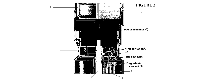
Thus, Figure 1 shows an explosive cartridge (1) suitable for use in seismic
exploration.
The explosive composition and deactivating agent remain sealed in their
respective
chambers (2, 3). Therefore, subject to the stability of the emulsion explosive
composition,
CA 02714548 2010-07-29
WO 2009/094715 PCT/AU2009/000102
- 26 -
the cartridge (1) is a storage stable product.
The cartridge also includes a small diameter axial channel (4) extending down
within the
body of the cartridge (1) from the deactivating agent chamber (3) through the
explosive
composition. This channel (4) is defined by a wall formed from a polymeric
material that
is degradable on contact with the deactivating agent. In the arrangement shown
in Figure 1
the channel (4) is empty since the deactivating agent has not been released
from the
chamber (3). A seal (not shown in detail) is provided between the deactivating
agent
chamber (3) and the channel (4), this seal being designed so that breakage of
it will cause
release of deactivating agent from chamber (3) into channel (4) extending
through the
explosive composition.
The upper end of the cartridge (1) is adapted to receive a cylindrical
detonator (5). When
the cartridge (1) is to be used in the field, this detonator (5) is inserted
into a detonator-
receiving channel (6) extending into the body of the cartridge (1). In the
embodiment
shown the detonator-receiving channel (6) is provided as an extension of the
channel (4).
The action of inserting the detonator into the detonator-receiving channel (6)
causes the
seal between the deactivating agent chamber (3) and the channel (4) to be
broken thereby
releasing deactivating agent into the channel (4). However, contact between
the
deactivating agent and the explosive composition is prevented by the walls of
the channel
(4) and the deactivating agent must first penetrate these walls before
contacting explosive
composition.
Although not shown, it may be necessary for the design to include some kind of
air inlet
(or breather tube) to allow air into the deactivating agent chamber (3) as
deactivating agent
flows out. In the absence of an air inlet, flow of deactivating agent may be
restricted.
Generally, air will only be allowed into the deactivating agent chamber (3)
when the
cartridge is being used, thereby preventing leakage of the deactivating agent.
Surface tension effects of the deactivating agent may also influence design or
the
characteristics of the deactivating agent to be used. Although also not shown
it may be
CA 02714548 2016-02-04
- 27 -
useful to allow the deactivating agent once released to come into contact with
a wick or
open cell foam that extends down into the channel (4) and that has the effect
of
conducting/drawing deactivating agent down into the channel (4).
The walls of the channel (4) are made of a degradable (polymeric) material
that may be
hydrolysed by water present in the aqueous deactivating agent. On contact of
the
deactivating agent and the walls of the channel (4) the deactivating agent
therefore
(slowly) degrades the walls. Whilst the walls remain intact no contact of the
deactivating
agent and explosive composition takes place and this delay allows a user of
the cartridge
(1) sufficient time to load the cartridge into a blasthole and attempt
detonation of the
cartridge (1) as intended. Thus, the functionality of the cartridge (1)
remains intact even
though the deactivating agent has been released from the chamber (3)
originally containing
it.
After a predetermined period of time (usually selected to be a number of
months) the walls
of the channel (4) will have been dissolved/consumed/weakened by the
deactivating agent.
The integrity of the walls is therefore lost and the deactivating agent comes
into contact
with the explosive composition. The deactivating agent then causes
crystallisation of the
emulsion explosive composition thereby rendering it safe. Tests in a typical
chart
configuration (10mm diameter cavity in a 57mm diameter charge) indicate that a
commercially available seismic emulsion explosive (MagnagelTm; Orica) can
become
insensitive to a No. 8 detonator 1 g PETN based charge within a month of
exposure to a
deactivating agent (Petra AG Special Liquid; Akzo Nobel).
Although not shown in Figure 1 the lower end of the cartridge (1) may also be
shaped in
order to be inserted into the detonator-receiving channel of an adjacent
cartridge (1A).
Thus, forming like cartridges into a train of cartridges can also result in
release of
deactivating agent from the chamber (3) in which it is originally contained.
The upper and
lower ends of the cartridge (1) may also contain cooperating features, such as
screw
threads, to enable cartridges to be secured together.
CA 02714548 2010-07-29
WO 2009/094715 PCT/AU2009/000102
- 28 -
In the embodiment described when released the deactivating agent flows into
channel (4)
running essentially the entire length of the explosive composition included in
the cartridge
(1). This is a preferred arrangement and the volume of the cavity is
configured to be such
that in use it will contain sufficient deactivating agent to deactivate the
entirety of the
explosive composition (over time). After the wall of the channel (4) has been
broken
down by action of the deactivating agent, explosive composition adjacent to
the
deactivating agent and thus adjacent to the detonator when positioned in the
cartridge will
be first exposed to the deactivating agent. This region of the explosive
composition
therefore comes into contact with the highest concentration of deactivating
agent thereby
promoting the fastest and most effective deactivation of the explosive
composition. Other
arrangements are of course possible.
In an alternative arrangement the deactivating agent flows into an annular
cavity provided
in the outer periphery of the cartridge body. In this embodiment it will be
appreciated that
the degradable material is provided on the outer surface of the emulsion
preventing contact
between the explosive composition and the deactivating agent (when released).
When the
material is degraded by the deactivating agent, the deactivating agent will
contact outer
regions of the explosive charge first. However, assuming the cartridge is used
with a
detonator in a central detonator-receiving passage, this embodiment suffers
the potential
drawback that explosive composition far removed from the location of the
detonator will
be deactivating agented first. There is therefore a greater risk of failure to
deactivate the
explosive composition if the deactivating agent action does not penetrate
radially into the
explosive composition (towards the location of the detonator). This embodiment
does
however have the advantage of a high surface area of contact between the
deactivating
agent and explosive composition.
As a further alternative, the deactivating agent may flow into a cavity
provided over the
top of the body of explosive composition provided in the cartridge. However,
this
embodiment suffers the potential disadvantage of low surface area of contact
between the
deactivating agent and explosive composition and this can lead to slow and/or
incomplete
deactivation of the explosive composition. Other alternatives are of course
possible within
CA 02714548 2016-02-04
- 29 -
the context of the present invention.
Figures 2 and 3 illustrate another embodiment of the present invention. Figure
2 illustrates
an arrangement before release of the deactivating agent and Figure 3 an
arrangement when
the deactivating agent is released. The Figures show an exploded view of only
a portion of
the cartridge.
Figures 2 and 3 show an explosive cartridge (1) in the form of an elongate
cylinder made
of a suitably rigid plastic. The cartridge includes a sealed chamber (2)
containing an
explosive composition and a further sealed chamber (3) containing a
deactivating agent.
During storage and transport of the cartridge (1) the deactivating agent and
explosive
composition remain sealed in their respective chamber (2,3).
The cartridge (1) also includes a small diameter axial channel (4) extending
down within
the body of the cartridge (1) from the deactivating agent chamber (3) through
the explosive
composition. This channel is provided off-centre and is distinct from the
channel into
which a detonator (5) is provided. The walls of the channel (4) may be formed
of a porous
material that in use will allow deactivating agent to be communicated to the
explosive
composition and that has sufficient structural rigidity to define a channel
adjacent or
through the explosive composition.
At the top (entrance) to the channel (4) there is an arrangement that is
designed to cause
release of deactivating agent from chamber (3) into the channel (4) when the
cartridge (1)
is to be used. This arrangement includes an elongate element (7) projecting
upwardly from
the top of the channel (4). This element (7) may be a tube (7A) that is
adapted at one end
to pierce a correspondingly located (rubber) seal (8) provided on the lower
end of the
deactivating agent chamber (3). The element (7) communicates at its lower end
with a seal
(9) provided over the entrance to the channel (4). This seal (9) is made of a
material that is
degradable on contact with the deactivating agent.
Prior to use the seal (8) is in tact and the seal (8) and element (7) are in
close proximity to
CA 02714548 2010-07-29
WO 2009/094715 PCT/AU2009/000102
- 30 -
each other. This arrangement is shown in Figure 2. In use of the cartridge,
the
deactivating agent chamber (3) is displaced downwards relative to the element
(7) and this
occurs as a result of engagement of the upper end of the cartridge (1) with an
engagement
member (10). In the embodiment shown the inner surface of the upper end of the
cartridge
(1) includes screw threads adapted to engage corresponding screw threads
provided on the
outer surface of the engagement member (10). The member (10) may be a
specially
designed cartridge cap or the lower end of another cartridge (1). The action
of screwing
the member (10) into the top of the cartridge (1) causes the deactivating
agent chamber (3)
to be displaced downwards. In turn this causes the piercing element (7) to
pierce the
(rubber) seal (8). Deactivating agent then flows down through the element (7)
thereby
coming into contact with the degradable seal (9). This is shown in Figure 3.
As already
noted, an air inlet or breather tube may be required to ensure flow of the
deactivating
agent, and surface tension effects may need to be taken into account too.
Preferably, the
air inlet/breather tube is "activated" only when the member (10) is screwed
into the top of
the cartridge (1) in order to release the deactivating agent. This prevents
leakage of
deactivating agent prior to use.
After a predetermined period of time the seal (9) will be
dissolved/consumed/weakened by
the action of the deactivating agent. The integrity of the seal is lost
thereby allowing
deactivating agent to drain into the channel (4). The deactivating agent then
flows through
the porous/permeable walls of the channel and into contact with the explosive
composition.
The deactivating agent goes on to desensitise the explosive composition
thereby rendering
it safe.
Figure 11 shows an explosive cartridge (1) suitable for use in seismic
exploration. The
explosive composition and deactivating agent remain sealed in their respective
chambers
(2, 3). The deactivation agent is confined by a flexible membrane that is in
the form of an
elongate plastic or rubber sheath (11). The sheath (11) is closed at one end
at the base of
the cartridge (1) and sealed at the other end by a cap (12).
A support member in the form of a helical spring (13) is provided internal to
the sheath
CA 02714548 2010-07-29
WO 2009/094715 PCT/AU2009/000102
-31 -
(11). The helical spring (13) is anchored at its lower end to an internal wall
of the
cartridge (1). At its upper end the helical spring (13) is attached to the cap
(12) that seals
the sheath (11). The helical spring (13) supports the sheath (11) and in the
embodiment
shown the flexible membrane is in an extended position. In this position the
deactivating
agent is prevented from contacting the explosive composition. The cap (12)
engages a
release mechanism and this is more clearly illustrated in Figures 12-14.
Figures 12-15 show the cap (12) being gripped by a pair of retaining arms
(14). These
arms (14) are hinged towards their upper ends and themselves extend from a
fitting (15).
The cap (12) is configured to be gripped by the arms (14) and in the
embodiment shown
the cap (12) has shoulder portions under which the arms (14) are initially
positioned.
Towards its upper end the fitting (15) is in contact with a creep member (16)
in the form of
a plastic rod having known creep properties. In the extended position the
helical spring
(13) will exert a withdrawing forces against the creep member (16) through the
cap/fitting
(12, 15) assembly. Prior to use of the cartridge (1) this force is prevented
from deforming
the creep member (16) by a sliding member (17) that engages the upper end of
the fitting
such that downward movement of the fitting (15) and thus of the creep member
(16) are
prevented. In the extended position the arms (14) are prevented from splaying
outwards
about their hinges due to the configuration of adjacent internal wall portions
of the
cartridge (1).
Prior to use the sliding member (16) engages the fitting (15) and covers a
detonator
receiving passage (18) provided in the cartridge (1). When the cartridge (1)
is used in the
field the sliding member (17) is moved across to reveal the detonator
receiving passage
(18) allowing a detonator (5) to be inserted into the body of the cartridge
(1). The
detonator wires (5A) are guided and retained by wall portions (17A) provided
on the
sliding member (17). It will be appreciated that in the embodiment shown the
detonator
(5) cannot be inserted into the detonator receiving passage (18) until the
sliding member
(17) has been moved across from the position in which it engages the upper end
of the
fitting (15).
CA 02714548 2010-07-29
WO 2009/094715 PCT/AU2009/000102
- 32
When the fitting (15) is no longer engaged by the sliding member (17) the
withdrawing
force exerted by the helical spring (13) will be communicated to the creep
member (16).
In turn this will initiate creep (and downward deflection) in the creep member
(16). Figure
13 shows the initial situation on release of the fitting (15) from engagement
with the
sliding member (17). The fitting (15) has been withdrawn slightly into the
body of the
cartridge (1) but further downward movement of it is prevented by suitably
positioned
retaining legs (19) provided on an internal wall of the cartridge (1). At this
point the
withdrawing force exerted by the helical spring (13) is experienced by the
creep member
(16). The creep member (16) will be deformed under load of the helical spring
(13)
causing deflection of the creep member (16). This is shown more clearly in
Figure 14.
Downward deflection of the creep member (16) will allow the cap/fitting
(12,15) assembly
to move downwards into the body of the cartridge (1). When the cap/fitting
(12,15)
assembly has travelled a predetermined distance the retaining arms (14) are
allowed to
splay out by virtue of shape of the relevant internal wall portions of the
cartridge (1). The
shoulders of the cap (12) have the effect of forcing the arms (14) outwardly
but this
movement is initially constrained by suitably shaped internal wall portions of
the cartridge
(1).
When the arms (14) are splayed out the fitting (15) no longer engages the cap
(12) and the
cap (12) is suddenly released. Residual tension in the helical spring (13)
continues to act
on the cap (12) however so it is withdrawn further into the body of the
cartridge (1). As
the helical spring (13) travels from its extended position to retracted
position the sheath
(11) will collapse forcing deactivating agent out through holes provided in
the cap (12).
The deactivation agent is then free to contact the explosive composition so
that
desensitisation is commenced.
Figures 16 and 17 shows an explosive cartridge (1) useful in implementation of
the
invention. The cartridges (1) shown in these figures do not include a barrier
element as
required in accordance with the invention. The figures are nevertheless
believed to be
useful in illustrating embodiments of the present invention.
CA 02714548 2010-07-29
WO 2009/094715 PCT/AU2009/000102
-33 -
With respect to Figure 16 the cartridge (1) includes explosive composition
(20) which
typically is in a solid (cast) form, such as Pentolite (typically a PETN/TNT
and/or RDX
mix). The explosive composition (20) includes detonator receiving channels (6)
that
enable the cartridge to be initiated by different sized (diameter) detonators.
The cartridge
(1) includes an outer shell (21) that is made of a water-permeable or water-
degradable
material. In the field environmental water may permeate or degrade the shell.
The shell
(21) also defines passages (22) extending into the explosive composition (20).
The use of
this configuration and type of shell allows environmental water to come into
contact with
the explosive composition (20), and is thus useful in embodiments of the
invention where
this is intended/required. The explosive composition (20) includes a chemical
deactivating
agent. For example, the chemical deactivating agent may be distributed
throughout the
explosive composition (20) in the form of pellets or granules. The
pellets/granules may be
mixed with the explosives composition (20) before the composition (20) is
poured (cast)
into the outer shell (21). Additionally or alternatively the chemical
deactivating agent may
be provided within the material making up the outer shell (12).
Figure 17 shows another form of an explosive cartridge (1) useful in
implementation of the
invention. The cartridge (1) includes an explosive composition (20), such as a
cast
Pentolite explosive, surrounded by a shell (21). Chemical deactivating agent
may be
provided as described in relation to Figure 1. The shell (21) is water-
permeable or water-
degradable, as for the shell discussed in Figure 16. In Figure 17 the shell
(21) includes
radial members (22) extending into the bulk of the explosive composition. The
intention
here is that when the cartridge (1) comes into contact with water, water
dissolves the shell
(21) so that water is then conveyed into contact with and through the
explosive
composition, as required by certain embodiments of the invention described
herein. The
rate at which the shell (21) dissolves may be controlled by suitable selection
of material
used to form the shell (21).
Figure 18 shows and explosive cartridge (1) suitable for use in seismic
exploration. The
cartridge (1) includes an explosive composition (a) and deactivating agent (b)
in respective
CA 02714548 2010-07-29
WO 2009/094715 PCT/AU2009/000102
- 34 -
chambers (2,3). The chamber for the explosive composition (a) is in the form
of a
cylindrical shell comprising wall portions (2') sealed by a base (2"). The
explosive
composition (a) may be Pentolite, possibly in mixture with RDX and/or
aluminium
particles.
The explosive composition (a) and deactivating agent (b) are separated in
their respective
chambers by a base plate (14) that is loosely fitted at the lower end of the
chamber (3) for
the deactivating agent (b). The plate (14) may be formed of any suitable
material such as a
polyester or polycarbonate. The plate (14) may be provided with a double-sided
adhesive
to allow it to be positioned and retained in place ¨ the purpose of the plate
is to prevent
contact between the deactivating agent (a) and explosive composition (b). That
said,
depending upon the nature of the deactivating agent and explosive composition
it may be
possible to dispense with the plate (14) altogether.
The cartridge (1) also includes two detonator receiving channels (5')
extending into the
explosive composition (a). The cartridge (1) also includes a cap (15) at one
end. This cap
(15) is sized and shaped to fit, for example by interference fit, into the
shell housing the
explosive composition.
In practice the cartridge (1) may be provided as separate components that are
assembled
during loading of respective components and when used in the field. With
respect to
Figure 6, one component may be integrally formed (by injection moulding of a
plastics
material) to include and define, the cap (15), the detonator receiving
channels (5') and the
chamber (3) for the deactivating agent (b) as illustrated in Figures 19 and
20. The base
plate (14) and chamber/shell (2) for the explosive composition (a) are
separate
components. The chamber (2) is made up of a cylindrical tube comprising wall
portions
(2') and a base (2") that is attached at a lower end of the tube thereby
sealing it.
Figures 19 and 20 illustrate certain components shown in Figure 18. Thus,
Figures 19 and
20 show the cap (15), detonating receiving channels (5') and chamber (3) for
the
deactivating agent formed as a one-piece construction, for example by
injection moulding
CA 02714548 2010-07-29
WO 2009/094715 PCT/AU2009/000102
- 35 -
of a suitable plastics material. The chamber (3) for the deactivating agent is
sealed by a
separate plate (14). The cap (15) comprises a circular wall portion (15a) with
a lip (15b)
that enables the cap (15) to be secured (by interference fit) into a suitably
sized and shaped
chamber in which an explosive composition is provided (not shown in Figures 19
and 20).
The cap (15) is typically inserted into a tube forming. The wall portions (2')
extend above
and below the cap (15) once inserted and are adapted to allow attachment of
other
cartridges or a nose cone, for example by thread fitting. The internal surface
of the wall
portion (2') may include a lug or tab to engage the lip (15b) so as to
maintain the cap (15)
in position. The upper end of the cap (15) is open to allow for insertion of
at least one
detonator into respective detonator receiving channels (5'). The end of the
cap (15c) may
be sealed with a suitably sized and shaped lid (not shown) or be formed in an
injection
moulding process. The cap (15) and/or wall portions (2') may include apertures
to allow
water to enter the explosive cartridge. As noted the wall portion (2')
extending above the
position of the cap (15) may receive the lower end of another explosive
cartridge to form a
train of cartridges. In this regard a surface (15c) of the wall portion (2')
may be threaded to
mate with corresponding threads provided on the outer surface and at the base
of another
cartridge. Cartridges may also be coupled by interference fit or by clip
fasteners. The cap
(15) may include apertures or grooves (not shown) in the side wall thereof
extending
through the circular wall portion (15a) and lip (15b) through which detonator
leads may be
passed after a detonator loading.
The embodiment illustrated in Figures 18-20 may be implemented as follows. In
the
orientation shown in Figure 8 the plate (14) is removed and deactivating agent
inserted into
the chamber (3). The plate (14) is then replaced thereby sealing the chamber
(3). The seal
is loose in the sense that the chamber (3) is not liquid tight. Still in the
orientation shown
in Figure 20, a cylindrical tube defining the wall portions (2') of the
chamber (2) for the
explosive composition (a) is inserted over the cap (15) with the cap (15)
being retained in
place by interference fit between the wall portion (2') and cap lip (15b).
An explosive composition, such as Pentolite, can then be poured into the open
end of the
tube, thereby surrounding the chamber (3) and detonator receiving channels
(5'). If
CA 02714548 2010-07-29
WO 2009/094715 PCT/AU2009/000102
- 36 -
Pentolite is used it is cast above its melting point and allowed to solidify.
Solidification
may result in the formation of cracks and fissures extending through the bulk
of the
explosive composition. This may be desirable as such cracks and fissures allow
water to
travel through the explosive composition, as may be desired. Once the tube has
been
suitably filled with explosive composition, and the composition solidified as
might be
necessary, a base (2") is attached to the open end of the tube. The base (2")
and wall
portions (2') may form a seal by interference fit, male-female screw threading
or by clip
fastening.
In use the component so-formed is loaded with one or more detonators with the
detonator
leads being passed out of the cap (15) or upper part of wall portions (2') as
noted. The top
end of the cap (15) may itself be sealed using a lid made of water-degradable
material (not
shown).
One or more components of the cartridge may be water-degradable, and the
degradability
may be selective in order to provide enhanced control with respect to intended
deactivation
of the explosive composition.
In the embodiment described it is intended that the deactivating agent is
rendered mobile
by water entering the chamber (3) around the edges of the plate (14). The
plate may be
water-degradable. Additionally or alternatively the plate may include
apertures to allow
water entry into the chamber (3). Additionally or alternatively, the wall
portions of the
chamber (3) may also be water-degradable and/or include structures to allow
water to
enter the chamber (3) (the chamber (3) may itself be made of water-degradable
material to
facilitate water ingress). Water mobilises the deactivating agent and the
mobilised
deactivating agent may exit the chamber (3) for contact with explosive
composition via the
same (or different) route through which water entered the chamber (3).
Water may find its way into the chamber (3) in one or a combination of more
than one
way, as follows.
CA 02714548 2010-07-29
WO 2009/094715 PCT/AU2009/000102
- 37 -
Where respective components are joined together, for example the wall portions
(2')
forming the chamber (2) and the cap (15) or the wall portions (2') and base
(2"), the joint
may allow water ingress. In this case water would enter the chamber (3) around
the plate
(14) by migration through the bulk of the explosive composition. The
composition must
therefore allow water transport by the presence of artificial and/or intrinsic
water transport
structures.
Additionally or alternatively, water may enter the explosive composition
through the walls
(2') and/or base (2") of the chamber (2). One or both of these components may
include
channels/apertures to allow water entry and/or one or both may be water-
permeable or
water-degradable. The exact configuration will depend upon the form of, and
thus the
containment needs, of the explosive composition.
Additionally or alternatively, water may enter the chamber (3) via the cap
(15). Thus, the
cap (15) may include channels/apertures extending through the cap (15) and
into the
chamber (3), for example through an aperture between the inner surface (15c)
and the
chamber (3). The aperture may itself be sealed by a water-degradable material.
Water
may enter the cap (15) through loose fitting seals (between the cap (15) and
cap lid or
between the wall portion (2') and an adjacent cartridge when a train of
multiple cartridges
is assembled). The apertures/grooves for the detonator leads may also allow
water to enter
the cap. Apertures/grooves in the upper part of the wall portions (2') may
also allow water
ingress.
Irrespective of the way in which water enters the chamber (3), when the
deactivating agent
is mobilised it will exit the chamber (3) and contact the explosive
composition, thereby
commencing deactivation of the explosive composition.
The material making up the shell (21), passages (22) and/or radial members
(23) may be
formed of a material that may be degraded by the action of microorganisms. As
the shell
(21) is degraded this allows water present in the environment to contact the
chemical
deactivating agent provided in the explosive composition (20) or shell (21).
In turn this
CA 02714548 2010-07-29
WO 2009/094715 PCT/AU2009/000102
- 38 -
renders the chemical deactivating agent suitably mobile and/or active so that
the chemical
deactivating agent can commence desensitisation of the explosive composition.
The
microorganisms may also have the effect of acting on the explosive composition
to convert
it into less detonable or non-detonable by-products and/or by-products that
are more
environmentally friendly.
Embodiments of the present invention are now illustrated in the following non-
limiting
examples.
Example 1
This example was undertaken to assess the effect as deactivating agent of a
number of
different reagents. The reagents selected for initial screening were chosen
based on a
general knowledge of emulsion chemistry and of reagents that had caused
unwanted
crystallisation of emulsion explosive compositions. All reagents were used as
liquids and
can be categorised as water soluble, oil soluble or polar organic. Water was
used as a
control liquid. The following table details the various liquids used in this
experiment.
Table 1
Class Material Details
Water soluble Water (test control)
Ferric chloride 42% solution
Ferrous sulphate 10% solution
Magnesium nitrate 10% solution
Teric GN8 detergent 10% solution
Petro AG Special Liquid 50% solution in water
Oil soluble Propar 32 paraffin oil (test control)
Galoryl 626 10% solution in
Propar 32
Galoryl 640 10% solution in
Propar 32
Polar organic liquids Ethane-1,2-diol Pure liquid
Polyethylene glycol 600 Pure liquid
Propan-1,2-diol Pure liquid
Propan-2-ol Pure liquid
iso-Amyl alcohol Pure liquid
n-Hexylamine Pure liquid
Cyclo-Hexylamine Pure liquid
Octylamine Pure liquid
Acetone Pure liquid
CA 02714548 2010-07-29
WO 2009/094715 PCT/AU2009/000102
- 39 -
Teric GN8 is a 10% solution of nonylphenol ethoxylate oligomer with 8
ethoxylate units,
commercially available from Orica.
Petro AG Special Liquid is a 50% solution of sodium alkylnaphthalene
sulphonate,
commercially available from Akzo Nobel.
The screening test involved providing a 20m1 layer of the reagent under test
on top of 30g
of a typical emulsion explosive composition provided in a 100m1 glass beaker.
The
composition of the emulsion explosive composition is given in Table 2 below.
Table 2
Component wt.%
Ammonium nitrate 67.99
Sodium nitrate 3.01
Sodium perchlorate 10.45
pH buffer 0.34
Water 12.31
Emulsifier* 2.76
Sorbitan mono-oleate 0.56
Paraffin oil 2.58
100.00
*Adduct of polyisobutylene succinic anhydride with diethanolamine, diluted to
approximately 50% solution in paraffin oil.
Batches of the emulsion were prepared by as follows. Ingredients sufficient
for a total
emulsion mass of 3.0 kg were weighed out. Ammonium nitrate, sodium nitrate,
sodium
perchlorate (anhydrous), 30% lactic acid solution (neutralised to pH = 4 with
sodium
carbonate) and water were heated and stirred in a water-jacketed tank to form
a solution
with a temperature of 90 C. In the bowl of a 3 speed Hobart model N-50
planetary mixer
(water-jacketed and heated to 90 C), the components, paraffin oil, sorbitan
mono-oleate
and PiBSA-DEA were stirred with a wire whisk attachment at Speed setting 2 to
form an
oil/emulsifier solution at 90 C. With the Hobart mixer stirring at Speed 2,
the
nitrate/perchlorate solution was added evenly to the oil/emulsifier solution
over the course
of 5 minutes, forming an emulsion of the water-in-oil type. The mixer speed
was increased
CA 02714548 2010-07-29
WO 2009/094715 PCT/AU2009/000102
- 40 -
to Speed 3 for a further 5 minutes, giving a final emulsion product with
viscosity 70,000
centipoise at 70 C (as measured using a Brookfield RVT viscometer with spindle
1 at 50
rpm).
After the layer of reagent was provided on top of the emulsion explosive
composition the
condition of the emulsion was monitored. Reagents were rated according to how
fast they
penetrated and damaged the emulsion. This was assessed based on visual colour
and
texture changes of the emulsion and this was taken as being representative of
the degree of
crystallisation. The results for the water soluble, oil soluble and polar
organic, liquids are
illustrated in Figures 2, 3 and 4, respectively.
The chemistry of Petro AG Special Liquid is obviously important but reference
to this, or
any other, commercial product should not be regarded as limiting the present
invention.
Reference to commercial products in the present specification is intended to
show that the
invention may be implemented on the basis of existing products. Materials for
use in
practice of the invention may of course be prepared, rather than purchased, by
the
application or adaptation of known techniques.
Example 2
While some of the polar organic liquids tested provided relatively rapid and
effective
penetration of the emulsion explosive composition, Petro AG Special Liquid was
selected
as the reagent with the best overall performance. Petro AG Special Liquid is a
50%
strength solution of sodium alkyl naphthalene sulphonate in water and is
commercially
available from Alczo Nobel. This reagent is also useful in practice of the
present invention
from a number of other perspectives (it is water based non-flammable, has
relatively low
toxicity and odour, is non-volatile, may be manufactured in a non-hazardous
and easy
manner and is commercially available).
As further indication of the efficacy of the using Petro AG Special Liquid,
Figure 5 and 6
are photographs showing the effect of Petro AG Special Liquid on an emulsion
explosive
CA 02714548 2010-07-29
WO 2009/094715 PCT/AU2009/000102
- 41 -
composition of the type identified in Table 2. In Figure 5 the layer of Petro
AG Special
Liquid has just been provided on top of the emulsion explosive composition.
The layer of
Petro AG Special Liquid appears as a darker layer provided over the top of the
lighter
emulsion explosive composition provided in the bottom of the beaker. From the
scale
included in the photograph it can be seen that the emulsion explosive
composition initially
was approximately 3cm in depth and the Petro AG Special Liquid approximately
1.5cm.
Figure 6 shows the same beaker after the Petro AG Special Liquid has been in
contact with
the emulsion explosive composition for a period of two days. The effect of the
Petro AG
Special Liquid is believed to be immediately apparent when one compares
Figures 5 and 6
side-by-side. It will be noted that the "level" of emulsion composition has
dropped by
approximately 1 cm (effectively 33%). This shows that the Petro AG Special
Liquid has
had a significant impact on the integrity of the emulsion explosive
composition.
For comparison, the experiment was repeated using a commercially available
detergent
(Teric GN8). The results are shown in Figure 7 at the commencement of the test
and
Figure 8 after five days. The Teric GN8 and the emulsion explosive composition
are not
of sufficiently different colours for the interface between the two to be seen
clearly in
Figures 7 and 8. However, a marker has been included on the outside surface of
the beaker
to show the position of the interface between the two. It is immediately
apparent that, even
after five days, the detergent has had little effect on the emulsion explosive
composition. It
is possible that the detergent causes some crystallisation at the interface
with the emulsion
explosive composition but it is evident that Petro AG Special Liquid causes
massive
crystallisation several centimetres away from the interface and within the
body of the
emulsion explosive composition. The exact mechanism by which this
crystallisation
occurs is not well understood but this is not material to the invention.
Example 3
When actively mixed into an emulsion explosive composition (as per Table 2),
as opposed
to simple surface contact, about 3% by weight of Petro AG Special Liquid was
required to
cause enough crystallisation to render a 63mm diameter charge insensitive to a
No. 8
CA 02714548 2010-07-29
WO 2009/094715 PCT/AU2009/000102
- 42 -
detonator. The relationship between the amount of reagent (deactivating agent)
used, the
degree of crystallisation and the detonation performance is shown in Figure 9.
This figure
shows that 3% is the theoretical minimum amount of Petro AG Special Liquid
that would need
to available in a self-deactivating cartridge in accordance with the present
invention.
Example 4
In the proposed explosive cartridge in accordance with the present invention
there is no active
mixing of the deactivating agent and emulsion explosive composition. Indeed,
there is only a
static surface exposure of these two components. To examine whether this is
sufficient to
deactivate an emulsion explosive composition, paper-walled axial cavities
(10mm and 12 mm
in diameter, respectively) were created inside 57mm diameter emulsion charges.
Each cavity
was filled with Petro AG Special Liquid. Being porous, the paper allowed the
Petro AG
Special Liquid to instantly contact the emulsion explosive composition. This
may be regarded
as simulating the end of the period at which time a wall of material
degradable by the
deactivating agent loses its integrity and exposes the emulsion explosive
composition to the
deactivating agent. In this example the amount of Petro AG Special Liquid in a
10mm cavity
equates to 3% w/w of the charge while the 12mm cavity equates to 5% w/w of the
charge.
For both cavity sizes it was observed that crystallisation of the emulsion
proceeded slowly
radially outward from the axis of the cavity. The charges became highly
crystallised and were
found to be detonator-insensitive within one month, as confirmed by velocity-
of-detonation
(VOD) tests. The results are shown in Figure 10. This figure also shows a
control in which no
cavity/deactivating agent was used.
Example 5
500 ml water was heated to 45 C in a water bath. Pentolite was added to 200ppm
(200mg/L),
consisting of 7Oppm PETN and 130ppm TNT. Sodium hydroxide solution (0.004 M)
was
added in an amount of 0.2m1 from a stock solution of 10M. The resultant
solution was then
removed from the water bath and allowed to sit at room temperature (21 C)
overnight in the
dark. Samples were taken and analysed for PETN and TNT levels. The experiment
was
repeated using water as control. The results are presented in Table 3
below.
CA 02714548 2010-07-29
WO 2009/094715 PCT/AU2009/000102
- 43 -
Table 3
PETN TNT
(mg/L) (mg/L)
NaOH (0.004M) 40 1.0
Water 45 110
Table 3 demonstrates the conversion of TNT by the action of the strong alkali
sodium
hydroxide. Surprisingly, little or no detectable activity is present on the
PETN molecule.
Conversion of TNT by alkali is well established in the art and is known to
proceed via
mechanisms including, but not limited to, chemical reduction of the nitrate
groups and/or
removal of the nitrate groups.
The action of alkali on TNT is well established in the art for destruction of
TNT. It has,
however, to the authors knowledge, never been incorporated into an explosive
device for
purposes including, but not limited to, rendering the device less prone to
initiation and
more amenable to biodegradation.
This demonstration of the conversion of TNT in a Pentolite solution confirms
that an alkali
can be used to enhance the degradation of explosive devices, including
Pentolite based
devices.
Example 6
Iron degradation control
In this example, coated iron particles are used to demonstrate the effect of
NaC1 addition in
enhancing the degradation of Pentolite, presumably by effecting either,
degradation of the
barrier or, 'de-passivation' of the iron particles. This example has broad
application as iron
CA 02714548 2010-07-29
WO 2009/094715 PCT/AU2009/000102
- 44 -
particles may be maintained in a non-functional state until NaC1 is released,
thus initiating
degradation of the Pentolite.
Experimental
Iron powder (Cat.no. 00631, Fluka, Australia)(150 mg) was added to 3m1 RNW
buffer (1
mM KHCO3, 0.5 mM CaC12, 0.206 mM MgSO4, 8.95 M FeSO4, 0.25 mM HC1, pH
¨7.8). To one set of iron containing tubes NaCl was added at 3mM whilst a non-
iron
containing control was established with only RNW and 3mM NaCl. The reaction
commenced with the addition of Pentolite (acetone) solution to a final
concentration of
100ppm. Sacrificial sampling was performed for analysis after 1, 15 or 51
days' incubation
at room temperature in the dark. Samples were processed for analysis by
addition of 9 mL
of acetonitrile and subsequently analysed by HPLC-UV using standard methods.
Results of analysis are shown in the following table, demonstrating control of
iron
degradation of Pentolite by the use of a corrosion enhancer. Degradation of
Pentolite
increases in a time-dependent manner and is initiated by the presence of a
corrosion
enhancer.
NaC1 mediated degradation of Pentolite by Iron powder
PETN %TNT 0/0
Sample Time (days) PETN (mg/L)TNT (mg/L)
degradation degradation
1 31.2 64 0% 0%
Control RNW 15 33.2 68 0% 0%
51 35.2 59.6 0% 0%
1 31.2 64 0% 0%
Iron 15 52 68 0% 0%
51 36 60 0% 0%
1 31.2 64 0% 0%
Iron + NaC1 15 32 21.2 3.6% 68.8%
'51 15.2 <0.4 56.8% >97%
CA 02714548 2010-07-29
WO 2009/094715 PCT/AU2009/000102
- 45 -
Example 7
Iron degradation control
A control mechanism to maintain iron in an 'inactive' state for a
predetermined period
(shelf-life) is of key relevance to it's successful application. This control
mechanism can
be provided by coating the iron in a degradable barrier, preferably a water
soluble barrier.
Experimental
Iron powder (Cat.no. 12311 - Reidel-deHaen, Australia) (30 mg) was added to
two sets of
tubes and Pentolite stock solution was added directly to the iron powder and
the acetone
allowed to evaporate (dry). Alternatively, iron was added to RNW buffer (1 mM
KHCO3,
0.5 mM CaCl2, 0.206 mM MgSO4, 8.95 11M FeSO4, 0.25 mM HC1, pH ¨7.8) to make a
100 ppm Pentolite solution and thus suspending the iron powder (wet). Control
tubes
contained Pentolite stock solution only. Tubes were sacrificed for analysis
after 3 days and
10 days incubation at room temperature in the dark. Samples were processed for
analysis
by addition of 9 mL of acetonitrile and subsequently analysed by HPLC-UV using
standard methods.
Results are shown in the following table, demonstrating control of iron
degradation of
Pentolite. Degradation of Pentolite was accompanied by corrosion of the iron
powder with
an orange oxide layer forming above the grey iron powder.
CA 02714548 2010-07-29
WO 2009/094715 PCT/AU2009/000102
- 46 -
Degradation of Pentolite by iron wet form, but not dry form
Time PETN TNT PETN TNT
Sample
(days) (mg/L) (mg/L) degradation degradation
3 35.2 72.4 0% 0%
Control
33.6 60.8 0% 0%
3 37.6 77.2 0% 0%
Dry iron
10 34.8 65.2 0% 0%
3 2.8 0.4 92% 99%
Wet iron
10 1.2 <0.4 96% >99%
Example 8
5
Degradation of PETN (SPC)
Sodium percarbonate (SPC) has been used in the present example as it is a
stable solid
complex of Sodium Carbonate and Hydrogen Peroxide. This compound thus combines
10 oxidative power, which, once exhausted, leaves an alkaline environment
to degrade alkali
sensitive compounds eg. TNT. In addition to these 'simple' reactions, peroxide
can
establish catalytic cascades, particularly, but not exclusively, in the
presence of metals (eg.
Iron).
Experimental
Sodium Percabonate (SPC) was purchased from Sigma-Aldrich, Australia (Cat#
371432)
and solutions, once prepared, were used immediately. A 100 mM SPC solution was
made
in RNW buffer, which is a water-based buffer exhibiting moderate general
hardness and
alkalinity (1 mM KHCO3, 0.5 mM CaCl2, 0.206 mM MgSO4, 8.95 I.LM FeSO4, 0.25 mM
HC1, pH ¨7.8). Two ten-fold serial dilutions were made of this solution into
the same
buffer, representing 10mM and 1mM SPC. A Pentolite (acetone) solution was
added to
200ppm in a volume of 3mL per reaction and incubated at room temperature
overnight in
CA 02714548 2010-07-29
WO 2009/094715 PCT/AU2009/000102
- 47 -
the dark. Samples were sacrificed by addition of 9 mL acetonitrile and
TNT/PETN were
analysed by HPLC-UV using standard methods.
Degradation of Pentolite by sodium percarbonate
PETN %TNT
Sample PETN (mg/L) TNT (mg/L)
degradation degradation
Control 59.2 119.6 0% 0%
1 mM SPC -57.6 102.8 2.7% 14%
mM SPC 53.6 2.8 9.5% 97.7%
100 mM SPC 10 <0.4 83.1% >99.7%
5
The reference to any prior art in this specification is not, and should not be
taken as, an
acknowledgment or any form of suggestion that that prior art forms part of the
common
general knowledge in Australia.
10 Throughout this specification and the claims which follow, unless the
context requires
otherwise, the word "comprise", and variations such as "comprises" and
"comprising", will
be understood to imply the inclusion of a stated integer or step or group of
integers or steps
but not the exclusion of any other integer or step or group of integers or
steps.