Sélection de la langue

Search

Sommaire du brevet 2714633 

Énoncé de désistement de responsabilité concernant l'information provenant de tiers

Une partie des informations de ce site Web a été fournie par des sources externes. Le gouvernement du Canada n'assume aucune responsabilité concernant la précision, l'actualité ou la fiabilité des informations fournies par les sources externes. Les utilisateurs qui désirent employer cette information devraient consulter directement la source des informations. Le contenu fourni par les sources externes n'est pas assujetti aux exigences sur les langues officielles, la protection des renseignements personnels et l'accessibilité.

Disponibilité de l'Abrégé et des Revendications

L'apparition de différences dans le texte et l'image des Revendications et de l'Abrégé dépend du moment auquel le document est publié. Les textes des Revendications et de l'Abrégé sont affichés :

  • lorsque la demande peut être examinée par le public;
  • lorsque le brevet est émis (délivrance).
(12) Brevet: (11) CA 2714633
(54) Titre français: DISPOSITIF DE NETTOYAGE D'APPLICATEUR DE PEINTURE
(54) Titre anglais: PAINT APPLICATOR CLEANING DEVICE
Statut: Accordé et délivré
Données bibliographiques
Abrégés

Abrégé français

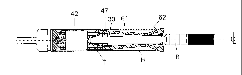
L'invention porte sur un dispositif pour nettoyer un pinceau de peinture B, lequel dispositif comporte un arbre (1) qui est fixé dans un moyeu (2) moulé autour de l'arbre. A l'opposé de l'arbre, le moyeu comporte un tourillon (3) avec un filetage externe (4) et une douille (5) comportant un alésage (6) débouchant, au niveau de l'extrémité du tourillon, avec un contre-perçage (7). Un épaulement (8) est présent à l'extrémité interne du contre-perçage. Au niveau d'une partie de plus grand diamètre (9) du moyeu, celui-ci comporte un petit collier (10), fournissant, au niveau d'une face d'extrémité (11), une butée (12). Derrière le collier, se trouve une rainure circonférentielle (14). Un dispositif de localisation de pointe de pinceau de peinture (21) est partiellement renfermé dans la douille (5). Ce dispositif comporte une tige interne (22), qui comporte un alésage (23) avec un fond (24) formant une butée pour un ressort (25). La tige (22) présente une taille d'espacement dans l'alésage (6). A l'extérieur de la tige, se trouve un collier externe (26), qui présente une taille d'espacement dans le contre-perçage (7). A l'intérieur de la tige, à l'extérieur du fond (24), le dispositif de localisation de pointe comporte une série d'épaulements (28) dans une douille (29) débouchant à l'extrémité externe du dispositif de localisation et dimensionnée de façon à recevoir une pointe de manche de pinceau de peinture. Cette extrémité de douille présente un diamètre externe (30) intermédiaire entre le diamètre de la tige (22) et celui du collier (26). La partie d'extrémité de la douille présente une bifurcation avec deux crans en forme de U divergents (31). Lorsque le dispositif de localisation de pointe s'étend hors de la douille ou, tout au moins, n'est plus positionné radialement de façon précise par celle-ci, il reste positionné par l'arbre de manche de pinceau de peinture (support 41), décrit à présent. Il s'agit d'un moulage en matière plastique avec une partie tubulaire (42) comportant un filetage interne (43), complémentaire du filetage externe (4). Deux queues (44) s'étendent à partir de la partie tubulaire. Les queues sont diamétralement opposées l'une à l'autre et portent des mâchoires (45) à leurs extrémités distales. A son extrémité proximale, la partie tubulaire comporte un collier interne (46), avec un diamètre interne (47) inférieur au diamètre interne du filetage (43). Le diamètre (47) est un diamètre d'espacement pour la douille de pointe (29) du dispositif de localisation de pointe. Par conséquent, le collier interne (46) assure les deux fonctions de localisation radiale du dispositif de localisation de pointe et de localisation longitudinale à l'encontre de l'action du ressort (25), dans une position déterminée par la position du support d'arbre par rapport au moyeu. Des pinceaux à long manche peuvent bien sûr maintenir le dispositif de localisation de pointe plus loin à l'intérieur de la douille du moyeu.


Abrégé anglais


A device for cleaning a paint brush B has a shaft (1) is fast in a hub (2)
moulded around the shaft. Opposite from
the shaft, the hub has a spigot (3) with an external screw thread (4) and a
socket (5) having bore (6) opening at the end of the spigot
with a counter-bore (7). A step (8) is provided at the inner end of the
counter bore. At a larger diameter portion (9) of the hub, it has
a small collar (10), providing at an end face (11) an abutment (12). Behind
the collar is a circumferential groove (14). A paint brush
tip locator (21) is partially housed in the socket (5). It has an inner stem
(22), which has a bore (23) with a bottom (24) forming an
abutment for a spring (25). The stem (22) is a clearance size in the bore (6).
Outwards of the stem is an external collar (26), which
is a clearance size in the counter-bore (7). Within the stem, outwards of the
bottom (24), the tip locator has a series of step (28)
in a socket (29) opening at the outer end of the locator and sized to receive
a paint brush handle tip. This socket end has an outer
diameter (30) intermediate the diameter of the stem (22) and the collar (26).
The end portion of the socket is bifurcated with two
divergent U-shaped nicks (31). When the tip locator is extended out of the
socket or at least no longer accurately radially located by
it, it still located by the paint-brush-handle shank (holder 41), now
described. It is a plastics material moulding with a tubular portion
(42) having an internal screw thread (43), complementary to the external screw
thread (4). Two tangs (44) extend from the tubular
portion. The tangs are diametrically opposite each other and carry jaws (45)
at their distal ends. At their proximal ends, the tubular
portion has an internal collar (46), with an internal diameter (47) less than
the internal diameter of the thread (43). The diameter
(47) is a clearance diameter for the tip socket (29) of the tip locator. Thus
the internal collar (46) performs the dual functions of
the radially locating the tip locator and longitudinally locating against the
action of the spring (25), in a position determined by the
position to shank holder with respect to the hub. Long handled brushes can of
course hold the tip locator further within the socket
of the hub.

Revendications

Note : Les revendications sont présentées dans la langue officielle dans laquelle elles ont été soumises.


9
What is claimed is:
1. A paint applicator cleaning device comprising:
.cndot. a drive shaft;
.cndot. a hub in communication with the draft shaft, wherein the drive
shaft protrudes from
one end of the hub, the hub having:
.cndot. a male screw thread on a spigot extending oppositely from the drive
shaft and
coaxial therewith,
.cndot. a coaxial socket opening into the spigot from its end remote from
the drive shaft
and
.cndot. an external abutment against longitudinal movement positioned
between
the drive shaft and the spigot;
.cndot. a paint-brush-handle tip locator having:
.cndot. a socket at one end adapted to receive a paint-brush-handle tip and
.cndot. a stem at its other end sized to be received coaxially in the
socket of the
hub;
.cndot. a spring housed, in the socket in the hub for urging the tip
locator outwards of the
socket;
.cndot. a paint-brush shank holder having:
.cndot. a tubular portion with a female thread complementary to the male
screw
thread of the hub,
.cndot. a plain bore for centring the socket of the tip locator,
.cndot. a pair of tangs extending generally in the direction of the central
axis of the
female thread from one end of the tubular portion and spaced on opposite sides
of
the central axis and
.cndot. a pair of jaws at the distal ends of the tangs for gripping the
paint brush
shank; and
.cndot. a sleeve sized to surround the tubular portion and extend between
the
abutment and the jaws, the jaws and the tubular portion being
complementarily formed whereby threading of the shank holder towards the hub
urges the jaws towards each other.

10
2. A cleaning device as claimed in claim 1, wherein the shank holder is a
moulding of
plastics material, rendering the tangs resilient for their separation on
threading of the shank
holder away from the hub.
3. A cleaning device as claimed in claim 1 or 2, wherein:
.cndot. the tubular portion of the shank holder has an internal collar,
providing the plain bore
and having an internal diameter smaller than its female thread, and
.cndot. the tip locator has an external diameter of its socket end sized to
fit within the collar.
4. A cleaning device as claimed in any one of claim 1, 2 or 3, wherein the tip
locator has an
external collar larger in diameter than the external diameter of its socket
end, the
arrangement being such that the shank holder captivates the tip locator
between the internal
collar and the hub, with the spring being captivated by the captivated tip
locator.
5. A cleaning device as claimed in claim 4, wherein the external collar is
sized to be
received within the coaxial socket of the hub.
6. A cleaning device as claimed in claim 4 or 5, wherein the socket end of the
tip locator has
a diameter reduced from the external collar and the coaxial socket has a
complementary
counter-bore, the arrangement limiting movement of the tip locator inwards of
the hub.
7. A cleaning device as claimed in any one of claim 4, 5 or 6, wherein the
coaxial socket
and the tip locator are dimensioned for bottoming of the tip locator in the
socket with the
external collar clear of the inner end of the counter-bore when the shank
holder is threaded
fully onto the hub.
8. A cleaning device as claimed in claim 7, wherein the outer end of the tip
locator and/or
the inner side of the internal collar are tapered for centring of the tip
locator in the shank
holder.
9. A cleaning device as claimed in any one of claims 1 to 8, wherein the tip
locator has a
bore in its inner end for receiving the spring.
10. A cleaning device as claimed in any one of claims 1 to 3, wherein both the
tip locator and
the socket in the hub are formed with spring engagements, whereby the spring
is engaged
with each and the tip locator is retained with the device.
11. A cleaning device as claimed in any one of claims 1 to 10, wherein the tip
locator has
steps in its socket for centring different sizes of paint brush tip.

11
12. A cleaning device as claimed in claim 3 or any one of claims 3 to 11 as
appendant to
claim 3, wherein the tip locator is dimensioned to extend out of the internal
collar when its
external collar abuts the internal collar, the portion of the tip locator so
extending being
bifurcated to receive a paint brush tip wider than it is thick.
13. A cleaning device as claimed in any one of claims 1 to 12, wherein the
complementary
formation of the jaws are wedge faces for abutting the sleeve.
14. A cleaning device as claimed in any one of claims 1 to 13, wherein the
jaws have
concave gripping faces for centring a paint brush shank.
15. A cleaning device as claimed in claim 14, wherein the jaws are formed with
open bottom
slots set back from the gripping faces to provide the faces with resilience.
16. A cleaning device as claimed in any one of claims 1 to 15, wherein the
tubular portion of
the shank holder is smaller than the internal size of the sleeve.
17. A cleaning device as claimed in claim 16 wherein the tangs extend from the
tubular
portion at the same external diameter as the tubular portion in their free
state.
18. A cleaning device as claimed in any one of claims 1 to 17, including a
collar for centring
a paint roller cover on the device at the hub end of the device.
19. A cleaning device as claimed in claim 18, wherein the hub has a groove on
the drive shaft
side of its sleeve abutment and the collar has a rim dimensioned to locate in
the groove.

Description

Note : Les descriptions sont présentées dans la langue officielle dans laquelle elles ont été soumises.


CA 02714633 2015-12-31
1
PAINT APPLICATOR CLEANING DEVICE
The present invention relates to a paint applicator cleaning device.
Devices are known for cleaning paint brushes and paint roller sleeves and in
particular for spinning washing liquid, in particular water, out of them.
My existing paint brush cleaner is the subject of EP 0 684 909 / WO 9416909,
of which the abstract is as follows:
A drive attachment device, particularly adapted to receive and transmit drive
to the
handle of a paint brush, comprises a body having a socket for receiving the
end of a
paint brush, and resilient retaining means in the form of tension springs
mounted on
pegs to span an opening through which the handle of the paint brush is
introduced
when being fitted to the device. The tension springs exert sufficient force on
the paint
brush handle both to retain it in position against axial displacement and to
transmit
rotation when the body is rotated.
My existing paint cleaner is the subject of EP 0 805 760/ WO 9622890, of
which the abstract is as follows:
A drive transmission implement for rotating a paint roller body having an
axial
through-bore for releasably receiving a shaft, comprises a spindle having a
first end
portion adapted to receive drive to rotate it about its axis, a second end
portion
adapted to fit into the axial through-bore in the roller body, a clutch device
carried by
the spindle intermediate the end portions and means for retaining a roller
body fitted
on to the second spindle portion in engagement with the clutch device to
enable
rotational drive to be transmitted from the spindle to the roller body,
particularly for
cleaning.
I have become aware of CA 2,358,113 of which the abstract is as follows:
In a tool for removing liquid from paint brushes and rollers, it is known to
have a
plunger with a tight fitting spring at one end and a cylindrical cone shape
groove in
the other end. The plunger and spring are mounted as a floating self-centring
device
within a tube, which at one end has a stopper shoulder and a drill attachment
and at
the opposite end is open with threads on the nutter (sic) side of the tube,
this tube

CA 02714633 2010-08-10
WO 2009/095678
PCT/GB2009/000258
2
section of the invention is known as the arbour. Mounted inside the threaded
end of
the arbour tube is a collet, into which a paint brush would be placed, the
collet is used
to secure a paint brush into place within the invention. Mounted externally
round the
arbour tube is another tube which is held in position at the bottom by the
shoulder of
the arbour tube and at the opposite end with a pinching washer which is
positioned
below the threads at the top of the arbour tube. Mounted onto the threaded end
of the
arbour tube is a nut. The nut is open at both ends and is shaped to allow the
collet to
fit snugly within the nut so as, when tightened, to lock the collet into
position inside
the threaded end of the arbour tube.
Further, I have become aware of US 5,185,938 of which the abstract is as
follows:
An attachment securable to the chuck of a hand-held power drill and adapted to
clamp
either a paint brush or a paint roller, so as to spin the same for cleaning by
centrifugal
force. The attachment is made of three separate parts, namely: a jaw unit, a
sleeve
and a cap nut, the latter provided with a spindle for insertion into the power
tool
chuck. The jaw unit includes a screw portion threaded within the cap nut and
having
a cylindrical extension in turn extended by a pair of spring jaws for
receiving
therebetween and clamping the narrower portion of a paint brush handle
adjacent the
brush bristles. A sleeve surrounds the arms of the two jaws and its opposite
ends
engage the cap nut and conical wedging surfaces of the jaw heads. Rotation of
the cap
nut with respect to the jaw unit causes axial movement of the sleeve which in
turn
causes retraction of the jaw to clamp the brush handle. The outer surface of
the sleeve
has paint roller clamping ribs to hold a paint roller around the sleeve. In
the second
embodiment, the outer end of the sleeve is provided with slits defining
deflectable
lugs therebetween, which are deflected radially outwardly upon further
insertion of
the jaw heads within the sleeve, so as to provide additional clamping of the
paint
brush roller.
The object of the present invention is to provide an improved paint applicator
cleaning device, capable of accommodating as wide a range of paint brushes as
reasonably possible and of cleaning paint roller sleeves as well with the same
device.

CA 02714633 2010-08-10
WO 2009/095678
PCT/GB2009/000258
3
In my developments to this end, I have noted that paint brushes have varying
shapes of handle. In particular some have round tips and others have rounded
corner
rectangular section tips. Some are longer than others. Some permit better
gripping at
the bristle end of the handle than others. Some have a cross-sectional
dimension
mitigating against use of certain prior art features.
However, of central importance, in particular to well centred location of the
head of the brush, bearing in mind that it may be spun at 2,500 rpm by an
electric
drill, is not only a pair of jaws arranged to close at equal radial distance
from the
central axis of the device, but also a similarly well centred paint brush tip
locator.
The centring of the tip locator is a particular challenge, in view of the need
for it to be
differently axially positioned in the device with differing lengths of brush
handle.
Accordingly in my present invention I provide a paint applicator cleaning
device comprising:
= a drive shaft;
= a hub fast with the drive shaft, which protrudes from one end of the hub,
the
hub having:
= a male screw thread on a spigot extending oppositely from the drive shaft
and coaxial therewith,
= a coaxial socket opening into the spigot from its end remote from the
drive
shaft and
= an external abutment against longitudinal movement positioned between
the drive shaft and the spigot;
= a paint-brush-handle tip locator ("the tip locator") having:
= a socket at one end adapted to receive a paint-brush-handle tip and
= a stem at its other end sized to be received coaxially in the socket of
the
hub;
= a spring housed in the socket in the hub for urging the tip locator
outwards of
the socket;
= a paint-brush shank holder ("the shank holder") having:
= a tubular portion with a female thread complementary to the male screw
thread of the hub,

CA 02714633 2010-08-10
WO 2009/095678
PCT/GB2009/000258
4
= a plain bore for centring the socket of the tip locator,
= a pair of tangs extending generally in the direction of the central axis
of the
female thread from one end of the tubular portion and spaced on opposite
sides of the central axis and
= a pair of jaws at the distal ends of the tangs for gripping the paint
brush
shank; and
= a sleeve sized to surround the tubular portion and extend between the
abutment and the jaws, the jaws and the tubular portion being
complementarily formed whereby threading of the shank holder towards the
hub urges the jaws towards each other.
Preferably, the shank holder is a moulding of plastics material, rendering the
tangs resilient for their separation on threading of the shank holder away
from the
hub.
In the preferred embodiment:
= the tubular portion of the shank holder has an internal collar, providing
the
plain bore and having an internal diameter smaller than its female thread,
= the tip locator has an external diameter of its socket end sized to fit
within the
collar,
= the tip locator has an external collar larger in diameter than the
external
diameter of its socket end, the arrangement being such that the shank holder
captivates the tip locator between the internal collar and the hub, with the
spring being captivated by the captivated tip locator,
= the external step is sized to be received within the coaxial socket of the
hub,
= the socket end of the tip locator has a diameter reduced from the
external
collar and the coaxial socket has a complementarily counter-bore, the
arrangement limiting movement of the tip locator inwards of the hub,
= the coaxial socket and the tip locator are dimensioned for bottoming of
the tip
locator in the socket with the external collar clear of the inner end of the
counter-bore when the shank holder is threaded fully onto the hub,
= the outer end of the tip locator and/or the inner side of the internal
collar are
tapered for centring of the tip locator in the shank holder,

CA 02714633 2010-08-10
WO 2009/095678
PCT/GB2009/000258
= the tip locator has a bore in its inner end for receiving the spring.
It is envisaged that both the tip locator and the socket in the hub can be
formed
with spring engagements, whereby the spring is engaged with each and the tip
locator
5 is retained with the device.
Again in the preferred embodiment:
= the tip locator has steps in its socket for centring different sizes of
paint brush
tip,
= the tip locator is dimensioned to extend out of the internal collar when its
external collar abuts the internal collar, the portion of the tip locator so
extending being bifurcated to receive a paint brush tip wider than it is
thick,
= the complementary formation of the jaws are wedge faces for abutting the
sleeve,
= the jaws have concave gripping faces for centring a paint brush shank,
= the jaws are formed with open bottom slots set back from the gripping
faces to
provide the faces with resilience,
= the tubular portion of the shank holder is a clearance size with respect
to the
internal size of the sleeve,
= the tangs extend from the tubular portion at the same external diameter as
the
tubular portion in their free state,
= a collar is included for centring a paint roller cover on the device at
the hub
end of the device, the jaws centring paint roller cover remote from the hub,
= the hub has a groove on the drive shaft side of its sleeve abutment and
the
collar has a rim dimensioned to locate in the groove,
To help understanding of the invention, a specific embodiment thereof will
now be described by way of example and with reference to the accompanying
drawings, in which:
Figure 1 is a perspecti ve view of a paint applicator cleaning device
according
to the invention;
Figure 2 is a side view of the device of Figure 1 gripping a paint brush;
Figure 3 is a similar view of the device gripping a paint roller sleeve;

CA 02714633 2015-12-31
6
Figure 4 is a partially sectioned side view of a hub of the device;
Figure 5 is a cross-sectional side view of a tip locator of the device;
Figure 6 is similar view of a shank holder of the device;
Figure 7 is an end view of the shank holder;
Figure 8 is a partially sectioned view of the device gripping a small paint
brush; and
Figure 9 is a similar view of the de vice gripping a large paint brush.
Referring to the drawings, a device for cleaning a paint brush B and/or a
paint
roller sleeve S by spinning paint out of them is shown. Normally, the paint
will have
been diluted to some extent before spinning. Further, the cleaning process can
involve successive dilutions and spinnings.
Typically the spinning is carried out by means of an electric drill (not
shown)
with a drive shaft 1 of the device held in the drill's chuck. It will be
appreciated that
gripping of a paint brush with minimum eccentricity is important. The
description
below discloses features for enhancing concentricity.
The shaft is fast in a hub 2, of plastics material, which is moulded around
the
shaft. Opposite from the shaft, the hub has a spigot 3 with an external screw
thread 4
and a socket 5 having bore 6 opening at the end of the spigot with a counter-
bore 7. A
step 8 is provided at the inner end of the counter bore. At a larger diameter
portion 9
of the hub, it has a small collar 10, providing at an end face 11 an abutment
12.
Behind the collar is a circumferential groove 14.
A paint brush tip locator 21, that is a member for locating the tip T of a
handle
H of a paint brush B being cleaned on the central axis CL of the device, is
partially
housed in the socket 5 / bores 6,7. It has an inner stem 22, which has a bore
23 with a
bottom 24 forming an abutment for a spring 25. The stem 22 is a clearance size
in the
bore 6. Outwards of the stem is an external collar 26, which is a clearance
size in the
counter-bore 7. This arrangement provides that the tip locator bottoms in the
bores
with the collar abutting the step 8 between the bores. In this condition, the
spring is
compressed between the bottom 24 of the bore 23 and the bottom 15 of the bore
6.
Within the stem, outwards of the bottom 24, the tip locator has a series of
steps 28 in a

CA 02714633 2015-12-31
7
socket 29 opening at the outer end of the locator and sized to receive a paint
brush
handle tip. This socket end has an outer diameter 30 intermediate the diameter
of the
stem 22 and the collar 26. The end portion of the socket is bifurcated with
two
divergent U-shaped nicks 31.
The external diameter of the socket 29 is 19mm and the respective internal
diameters of the stepped portions of it are 16mm, 14mm,12mm, lOmm, with the
steps
being set 5mm apart.
Thus the tip locator can receive and centre a wide variety of paint brush
tips,
in fact the tips of all styles of brush that I am aware of up to a 4inch,
100mm, wide
brush. Further, since the tip locator can move against the spring 25, a
differing
lengths of brush handle are accommodated.
When the tip locator is extended out of the socket or at least no longer
accurately radially located by it, it still located by the paint-brush-handle
shank holder
41, now described. It is a plastics material moulding with a tubular portion
42 having
an internal screw thread 43, complementary to the external screw thread 4. Two
tangs
44 extend from the tubular portion. The tangs are diametrically opposite each
other
and carry jaws 45 at their distal ends. At their proximal ends, the tubular
portion has
an internal collar 46, with an internal diameter 47 less than the internal
diameter of the
thread 43. The diameter 47 is a clearance diameter for the tip socket 29 of
the tip
locator. Thus the internal collar 46 performs the dual functions of radially
locating
the tip locator and longitudinally locating against the action of the spring
25, in a
position determined by the position of the shank holder with respect to the
hub. Long
handled brushes can of course hold the tip locator further within the socket
of the hub.
The tip socket and the internal collar are such as to allow the bifurcated
portion of the tip socket to extend from within the collar. For brushes with
the largest
of tips, the latter can be centred in the internal collar itself. Such use can
force the tip
locator inwards of the internal collar altogether. To ease its return under
the action of
the spring, its end 48 and the inside face 49 of the internal collar are
tapered for
centring of the tip locator.

CA 02714633 2015-12-31
8
The jaws 45 have frusto-conical surfaces 50 facing back towards the tubular
portion and concave gripping faces 51. These are provided on bands 52, with
slots 53
open at both the end faces 54 of the jaws and the inner ends 55 of the faces
51. This
arrangement not only gives the jaws centring action, when gripping the shank
of a
paint brush handle, but also resilience enabling firm grip of the handle.
The jaws are driven together by an outer sleeve 61 acting in abutment with the
abutment 12 and the tapered jaw surfaces 50. The end 62 of the sleeve abutting
the
jaws being internally tapered. Thus as the hub and the shank holder are
threaded
together, the jaws are forced together for gripping a paint brush handle
between them,
the handle having already been thrust against the tip locator.
For cleaning a paint roller sleeve S, a split band 71, with a pair of
differing
diameter external surfaces 72,73 ¨ for different diameter sleeves ¨ is
provided with an
internal diameter 74 to be a light interference fit with the sleeve 61 and an
inside rim
75 for locating in the circumferential groove 14. In use the jaws allowed
spring out to
a diameter gripping the inside of the roller sleeve.

Dessin représentatif
Une figure unique qui représente un dessin illustrant l'invention.
États administratifs

2024-08-01 : Dans le cadre de la transition vers les Brevets de nouvelle génération (BNG), la base de données sur les brevets canadiens (BDBC) contient désormais un Historique d'événement plus détaillé, qui reproduit le Journal des événements de notre nouvelle solution interne.

Veuillez noter que les événements débutant par « Inactive : » se réfèrent à des événements qui ne sont plus utilisés dans notre nouvelle solution interne.

Pour une meilleure compréhension de l'état de la demande ou brevet qui figure sur cette page, la rubrique Mise en garde , et les descriptions de Brevet , Historique d'événement , Taxes périodiques et Historique des paiements devraient être consultées.

Historique d'événement

Description Date
Requête pour le changement d'adresse ou de mode de correspondance reçue 2020-11-18
Représentant commun nommé 2019-10-30
Requête pour le changement d'adresse ou de mode de correspondance reçue 2019-03-06
Accordé par délivrance 2016-11-01
Inactive : Page couverture publiée 2016-10-31
Préoctroi 2016-09-15
Inactive : Taxe finale reçue 2016-09-15
Un avis d'acceptation est envoyé 2016-04-19
Lettre envoyée 2016-04-19
Un avis d'acceptation est envoyé 2016-04-19
Inactive : Approuvée aux fins d'acceptation (AFA) 2016-04-15
Inactive : Q2 réussi 2016-04-15
Modification reçue - modification volontaire 2015-12-31
Inactive : Dem. de l'examinateur par.30(2) Règles 2015-11-20
Inactive : Rapport - Aucun CQ 2015-11-16
Retirer de l'acceptation 2015-11-16
Inactive : Demande ad hoc documentée 2015-11-09
Inactive : Rapport - Aucun CQ 2015-10-07
Inactive : Rapport - Aucun CQ 2015-09-11
Inactive : Rapport - Aucun CQ 2015-09-02
Inactive : Demande ad hoc documentée 2015-09-02
Inactive : Approuvée aux fins d'acceptation (AFA) 2015-07-08
Inactive : QS réussi 2015-07-08
Modification reçue - modification volontaire 2015-04-27
Inactive : Dem. de l'examinateur par.30(2) Règles 2015-01-09
Inactive : Rapport - Aucun CQ 2014-12-15
Lettre envoyée 2014-04-01
Inactive : Correspondance - Poursuite 2014-01-17
Lettre envoyée 2014-01-17
Exigences pour une requête d'examen - jugée conforme 2014-01-06
Toutes les exigences pour l'examen - jugée conforme 2014-01-06
Requête d'examen reçue 2014-01-06
Lettre envoyée 2012-03-14
Inactive : Demande ad hoc documentée 2012-02-22
Inactive : Lettre officielle 2012-02-22
Exigences relatives à la révocation de la nomination d'un agent - jugée conforme 2012-02-07
Inactive : Lettre officielle 2012-02-07
Inactive : Demande ad hoc documentée 2012-02-07
Exigences relatives à la nomination d'un agent - jugée conforme 2012-02-07
Demande visant la révocation de la nomination d'un agent 2012-01-31
Demande visant la nomination d'un agent 2012-01-31
Demande visant la révocation de la nomination d'un agent 2012-01-30
Demande visant la nomination d'un agent 2012-01-30
Inactive : Correspondance - PCT 2011-01-20
Requête visant le maintien en état reçue 2011-01-20
Inactive : Page couverture publiée 2010-11-15
Inactive : Notice - Entrée phase nat. - Pas de RE 2010-10-04
Inactive : Inventeur supprimé 2010-10-04
Inactive : CIB en 1re position 2010-10-01
Inactive : CIB attribuée 2010-10-01
Demande reçue - PCT 2010-10-01
Exigences pour l'entrée dans la phase nationale - jugée conforme 2010-08-10
Déclaration du statut de petite entité jugée conforme 2010-08-10
Demande publiée (accessible au public) 2009-08-06

Historique d'abandonnement

Il n'y a pas d'historique d'abandonnement

Taxes périodiques

Le dernier paiement a été reçu le 2016-01-20

Avis : Si le paiement en totalité n'a pas été reçu au plus tard à la date indiquée, une taxe supplémentaire peut être imposée, soit une des taxes suivantes :

  • taxe de rétablissement ;
  • taxe pour paiement en souffrance ; ou
  • taxe additionnelle pour le renversement d'une péremption réputée.

Les taxes sur les brevets sont ajustées au 1er janvier de chaque année. Les montants ci-dessus sont les montants actuels s'ils sont reçus au plus tard le 31 décembre de l'année en cours.
Veuillez vous référer à la page web des taxes sur les brevets de l'OPIC pour voir tous les montants actuels des taxes.

Historique des taxes

Type de taxes Anniversaire Échéance Date payée
Taxe nationale de base - petite 2010-08-10
Rétablissement (phase nationale) 2010-08-10
TM (demande, 2e anniv.) - petite 02 2011-01-31 2011-01-17
TM (demande, 3e anniv.) - générale 03 2012-01-30 2012-01-30
TM (demande, 4e anniv.) - petite 04 2013-01-30 2013-01-25
TM (demande, 5e anniv.) - petite 05 2014-01-30 2014-01-06
Requête d'examen - petite 2014-01-06
TM (demande, 6e anniv.) - petite 06 2015-01-30 2015-01-27
TM (demande, 7e anniv.) - petite 07 2016-02-01 2016-01-20
Taxe finale - petite 2016-09-15
TM (brevet, 8e anniv.) - petite 2017-01-30 2017-01-25
TM (brevet, 9e anniv.) - petite 2018-01-30 2018-01-11
TM (brevet, 10e anniv.) - petite 2019-01-30 2019-01-17
TM (brevet, 11e anniv.) - petite 2020-01-30 2020-01-09
TM (brevet, 12e anniv.) - petite 2021-02-01 2021-01-21
TM (brevet, 13e anniv.) - générale 2022-01-31 2022-01-24
TM (brevet, 14e anniv.) - générale 2023-01-30 2023-01-23
TM (brevet, 15e anniv.) - générale 2024-01-30 2023-12-25
Titulaires au dossier

Les titulaires actuels et antérieures au dossier sont affichés en ordre alphabétique.

Titulaires actuels au dossier
DAVID BRIAN TAYLOR
Titulaires antérieures au dossier
S.O.
Les propriétaires antérieurs qui ne figurent pas dans la liste des « Propriétaires au dossier » apparaîtront dans d'autres documents au dossier.
Documents

Pour visionner les fichiers sélectionnés, entrer le code reCAPTCHA :


Pour visualiser une image, cliquer sur un lien dans la colonne description du document. Pour télécharger l'image (les images), cliquer l'une ou plusieurs cases à cocher dans la première colonne et ensuite cliquer sur le bouton "Télécharger sélection en format PDF (archive Zip)" ou le bouton "Télécharger sélection (en un fichier PDF fusionné)".

Liste des documents de brevet publiés et non publiés sur la BDBC .

Si vous avez des difficultés à accéder au contenu, veuillez communiquer avec le Centre de services à la clientèle au 1-866-997-1936, ou envoyer un courriel au Centre de service à la clientèle de l'OPIC.


Description du
Document 
Date
(aaaa-mm-jj) 
Nombre de pages   Taille de l'image (Ko) 
Abrégé 2010-08-09 1 80
Revendications 2010-08-09 3 118
Description 2010-08-09 8 349
Dessins 2010-08-09 3 59
Dessin représentatif 2010-10-05 1 7
Revendications 2015-04-26 3 110
Description 2015-12-30 8 330
Dessin représentatif 2016-10-10 1 6
Rappel de taxe de maintien due 2010-10-03 1 113
Avis d'entree dans la phase nationale 2010-10-03 1 195
Rappel - requête d'examen 2013-09-30 1 118
Accusé de réception de la requête d'examen 2014-01-16 1 175
Avis du commissaire - Demande jugée acceptable 2016-04-18 1 161
Taxes 2013-01-24 1 155
PCT 2010-08-09 9 304
Correspondance 2011-01-19 1 34
Correspondance 2012-01-29 4 152
Correspondance 2012-01-29 2 62
Taxes 2012-02-06 1 14
Correspondance 2012-02-06 1 17
Taxes 2012-01-30 1 34
Correspondance 2012-01-30 4 152
Correspondance 2012-02-21 1 19
Correspondance 2012-03-13 1 13
Correspondance 2012-02-27 1 29
Taxes 2012-01-30 2 71
Taxes 2014-01-05 1 24
Correspondance 2014-03-31 1 9
Taxes 2015-01-26 1 25
Demande de l'examinateur 2015-11-19 3 185
Modification / réponse à un rapport 2015-12-30 7 216
Taxe finale 2016-09-14 1 40