Note : Les descriptions sont présentées dans la langue officielle dans laquelle elles ont été soumises.
CA 02714702 2010-09-09
1
"Method, device and computer program for planning
an aspirative fire detection system"
Description
The invention relates to a method, device and computer program for planning an
aspirative fire detection system.
An aspirative fire detection system is designed to extract representative air
samples from
a closed room, for example a warehouse or an IT server room, either
continuously or at
predetermined times or upon predetermined events, and feed them to a detector
module. The detector module serves to identify the physical or chemical
properties of
the supplied air samples so as to allow a conclusion to be drawn from said
properties as
to the chemical or physical state of the air within the closed room.
Figure 1 shows a schematic representation of one embodiment of an aspirative
fire
detection system. A pipe system 102 is arranged in a target room 101 to
aspirate air
samples through various intake openings. The pipe system 102 is equipped with
an
aspiration detector into which the air samples from the target room 101 are
fed to a
detector module 103 to detect fire characteristics, respectively to measure
oxygen and
other gases. A fan 104 is furthermore provided, serving to suck in the air
samples from
the target room through the pipe system. The suction power of fan 104 is
thereby
adapted to the respective pipe system 102.
To be understood by the term "fire characteristic" are physical parameters
subject to
measurable changes in the vicinity of a fire; e.g. the ambient temperature or
the
percentage of solids, liquids or gases in the ambient air such as smoke
particles, smoke
aerosols, vapor or fumes, for example.
DM VAN/2 772 7 1-000 1 4/77 1 5 5 05.1
CA 02714702 2010-09-09
2
Typical areas of application for aspirative fire detection systems are in the
monitoring of
spaces such as e.g. double floors, false ceilings, tunnels, ducts, poorly
accessible hollow
spaces, warehouse storage areas, high-bay warehouses, elevator shafts,
museums,
cultural facilities, freezer warehouses, air-conditioning systems and also the
monitoring
of rooms containing high value or important equipment such as e.g. rooms
housing data
processing equipment inside banks or other such similar facilities, or even
the data
processing equipment itself. To this end, representative portions of the room
air or the
cooling air are continuously extracted, these being referred to as air
samples. The air
samples are extracted through a pipe system which is mounted e.g. below the
ceiling.
In order to ensure effective monitoring of the respective room, aspirative
fire detection
systems need to be individually designed, i.e. planned, depending upon the
size and the
type of room to be monitored and the respective purpose of monitoring.
Different
parameters need to be considered in such planning including the desired
responsivity
(sensitivity) of the fire detection system, the size and configuration of the
pipe system,
and the number of intake openings in the pipe system. The optimal planning of
a fire
detection system is characterized by the components of the fire detection
system, in
particular the detector module and the pipe system, being adapted to the size
and type
of room to be monitored on the one hand and to the desired responsivity for
the room
monitoring on the other; i.e. neither overdimensioned nor underdimensioned.
Due to the
plurality of parameters to be considered, optimal planning is a relatively
complex
problem which, in practice, creates considerable difficulties for one skilled
in the art.
Based on this problem as defined, the task of the present invention is thus
specifying a
suitable and efficient method as well as a device and a computer program for
planning
an aspirative fire detection system.
This task is solved by a method in accordance with claim 1, a device in
accordance with
claim 9, and a computer program in accordance with claim 17. Advantageous
embodiments are indicated in the dependent claims.
DM VAN/277271-00014/7715505.1
CA 02714702 2010-09-09
3
With respect to the method for planning an aspirative fire detection system,
the
invention provides for planning the detector module of the fire detection
system with the
aid of at least one planning table on the one hand and planning the pipe
system of the
fire detection system with the aid of at least one pipe planning table on the
other. The
planning table and the pipe planning table enable the detector module and the
pipe
system to be easily, quickly and cost-efficiently dimensioned to the
respective
application scenario.
The detector module planning step preferably includes the following steps:
selecting a
number of intake openings and determining the sensitivity class to be achieved
for the
fire detection system based on the planning table and the number of intake
openings.
The detector module planning step can additionally include the step of
selecting a
desired sensitivity class and determining the required responsivity for a
detector module
in order to achieve the desired sensitivity class. The step of selecting the
detector
module based on the required responsivity and determining a sensitivity
setting for the
detector module based on the given detector module and the required
responsivity can
likewise be provided.
This procedure has the advantage of basing achievable sensitivity classes on
one central
influencing factor, namely the number of intake openings. Because depending on
the
number of intake openings, the A, B and C sensitivity classes pursuant the
European EN
54-20 standard can be achieved with any given detector module. Determining the
number of intake openings early on enables the achievable sensitivity classes
to be
easily and efficiently specified using the planning table. The desired
sensitivity class can
then be selected therefrom. Afterwards, a suitable detector module and an
appropriate
sensitivity setting can be easily and efficiently determined with the aid of
the planning
table.
The inventive planning method preferably further comprises the following
steps:
selecting an air filter and defining a planning table and/or a pipe planning
table based
on the air filter. The question of whether and what type of air filter is
provided has a
DM VAN/277271-00014/7715505.1
CA 02714702 2010-09-09
4
considerable influence on the design of the overall system. It is therefore
expedient to
provide for a different planning table depending on the type of air filter
selected.
In one preferred embodiment of the inventive solution, the pipe system
planning step
includes the following steps: selecting a desired pipe length, selecting a
pipe shape
based on the pipe length and the pipe planning table, and selecting a fan
voltage based
on the pipe length and shape. These steps enable the pipe system to be planned
easily
and quickly with the aid of the pipe planning table.
In one preferred realization of the inventive method, same comprises the
following
steps: selecting a desired class of pipe accessories and determining a pipe
planning table
based on the pipe accessory class. The step of selecting a desired pipe
accessory class
can hereto encompass the step of selecting one or more components from the
component group comprising condensate separators, detonation arrestors, valve
control
unit shut-off valves, detector boxes, sound suppressors and aspiration
detectors. By the
providing of a plurality of differing pipe planning tables which, depending
upon the
desired pipe accessory class, ultimately define the air resistance class,
planning the pipe
system is easy and simple. The air resistance classes can thereby relate to,
for example,
the "without pipe accessories," "slightly increased air resistance,"
"increased air
resistance" or "high air resistance" classes.
The invention furthermore relates to a device for planning an aspirative fire
detection
system having a detector module and a pipe system, wherein the device
comprises a
means for planning the detector module with the aid of a planning table and a
means for
planning the pipe system with the aid of a pipe planning table. The planning
table and
pipe planning table enable easy and efficient planning.
The means for planning the detector module preferably comprises a means for
selecting
a number of intake openings and a means for determining the achievable
sensitivity
classes based on the planning table and the number of intake openings. The
means for
planning the detector module can further comprise a means for selecting a
desired
sensitivity class, a means for determining a required responsivity for a
detector module
DM VAN/277271-00014/7715505.1
CA 02714702 2010-09-09
to achieve the desired sensitivity class, a means for selecting the detector
module based
on the required sensitivity and/or a means for determining a sensitivity
setting for the
detector module based on the detector module and the required sensitivity. In
this way,
a suitable detector module and its sensitivity setting can be quickly and
easily
determined on the basis of the planning table and the number of intake
openings.
In one preferred realization, the device according to the invention comprises
a means for
selecting an air filter and a means for determining a planning table and/or a
pipe
planning table based on the air filter. Since the selection of the air filter
can have
considerable influence on the planning, providing a plurality of planning
tables and the
determination of same based on the selected air filter can result in simple
and efficient
planning.
In one preferred embodiment, the means for planning the pipe system comprises
a
means for selecting a desired pipe length, a means for selecting a pipe shape
based on
the pipe length and the pipe planning table, and a means for selecting a fan
voltage
based on the pipe length and shape. This embodiment enables simple and quick
planning
of the pipe system.
The device according to the invention preferably comprises a means for
selecting a
desired pipe accessory class and a means for determining a pipe planning table
based on
the pipe accessory class. The means for selecting a desired pipe accessory
class can
thereby comprise a means for selecting one or more components from the
component
group comprising condensate separators, detonation arrestors, valve control
unit shut-
off valves, detector boxes, sound suppressors and aspiration detectors.
Planning the
pipe system depends to a considerable degree on the pipe accessory class.
Providing a
plurality of pipe planning tables based on the pipe accessory class to be used
during the
planning stage can achieve simple and efficient planning of the pipe system.
The described inventive method and inventive device can be accomplished or set
up by
means of a computer program. Hence, the invention further relates to a
computer
DM VAN/2772 7 1-000 1 4/77 1 5 5 05.1
CA 02714702 2010-09-09
6
program which includes instructions furnished to perform the inventive method
or set up
an inventive device when run on a computer.
The following will reference the accompanying drawings in describing an
embodiment of
the invention in greater detail.
Shown are:
Fig. 1 a schematic view of an aspirative fire detection system;
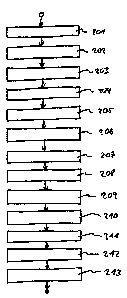
Fig. 2 a flow chart to illustrate an embodiment of the inventive method of
planning
an aspirative fire detection system, e.g. as according to Fig. 1;
Fig. 3 a list of possible air filter types for use in an aspirative fire
detection system,
e.g. as in accordance with Fig. 1;
Fig. 4a an embodiment of a planning table for planning a fire detection system
without an air filter;
Fig. 4b an embodiment of a pipe planning table for planning a fire detection
system
without an air filter when no other pipe accessory is used;
Fig. 4c an embodiment of a pipe planning table for planning a fire detection
system
without an air filter when a detector box and/or a valve control unit is/are
used as pipe accessory/accessories;
Fig. 4d an embodiment of a pipe planning table for planning a fire detection
system
without an air filter when an aspiration detector or condensate separator is
used as a pipe accessory;
Fig. 4e an embodiment of a pipe planning table for planning a fire detection
system
without an air filter when a detonator arrestor is used as a pipe accessory;
Fig. 5a an embodiment of a planning table for planning a fire detection system
having
an LF-AD type air filter;
DM VAN/277271-00014/7715505.1
CA 02714702 2010-09-09
7
Fig. 5b an embodiment of a pipe planning table for planning a fire detection
system
having an LF-AD air filter when no other pipe accessory is used;
Fig. 5c an embodiment of a pipe planning table for planning a fire detection
system
having an LF-AD air filter when a detector box and/or a valve control unit
is/are used as pipe accessory/accessories;
Fig. 5d an embodiment of a pipe planning table for planning a fire detection
system
having an LF-AD air filter when an aspiration detector or condensate separator
is used as a pipe accessory;
Fig. 5e an embodiment of a pipe planning table for planning a fire detection
system
having an LF-AD air filter when a detonation arrestor is used as a pipe
accessory;
Fig. 6a an embodiment of a planning table for planning a fire detection system
having
an LF-AD-1 type air filter;
Fig. 6b an embodiment of a pipe planning table for planning a fire detection
system
having an LF-AD-1 air filter when no other pipe accessory is used;
Fig. 6c an embodiment of a pipe planning table for planning a fire detection
system
having an LF-AD-1 air filter when a detector box and/or a valve control unit
is/are used as pipe accessory/accessories;
Fig. 6d an embodiment of a pipe planning table for planning a fire detection
system
having an LF-AD-1 air filter when an aspiration detector or condensate
separator is used as a pipe accessory;
Fig. 6e an embodiment of a pipe planning table for planning a fire detection
system
having an LF-AD-1 air filter when a detonation arrestor is used as a pipe
accessory;
DM VAN/277271-00014/7715505.1
CA 02714702 2010-09-09
8
Fig. 7a an embodiment of a planning table for planning a fire detection system
having
an LF-AD-2 type air filter;
Fig. 7b an embodiment of a pipe planning table for planning a fire detection
system
having an LF-AD-2 air filter when no other pipe accessory is used;
Fig. 7c an embodiment of a pipe planning table for planning a fire detection
system
having an LF-AD-2 air filter when a detector box and/or a valve control unit
is/are used as pipe accessory/accessories;
Fig. 7d an embodiment of a pipe planning table for planning a fire detection
system
having an LF-AD-2 air filter when an aspiration detector or condensate
separator is used as a pipe accessory;
Fig. 7e an embodiment of a pipe planning table for planning a fire detection
system
having an LF-AD-2 air filter when a detonation arrestor is used as a pipe
accessory;
Fig. 8a an embodiment of a planning table for planning a fire detection system
having
an SF-400/SF-650 type air filter;
Fig. 8b an embodiment of a pipe planning table for planning a fire detection
system
having an SF-400/SF-650 air filter when no other pipe accessory is used;
Fig. 8c an embodiment of a pipe planning table for planning a fire detection
system
having an SF-400/SF-650 air filter when a detector box and/or a valve control
unit is/are used as pipe accessory/accessories;
Fig. 8d an embodiment of a pipe planning table for planning a fire detection
system
having an SF-400/SF-650 air filter when an aspiration detector or condensate
separator is used as a pipe accessory;
Fig. 8e an embodiment of a pipe planning table for planning a fire detection
system
having an SF-400/SF-650 air filter when a detonation suppressor is used as a
pipe accessory;
DM_VAN/277271-00014/7715505.1
CA 02714702 2010-09-09
9
Fig. 9 the response sensitivity of three different detector modules; and
Fig. 10 different pipe shapes for a pipe system of a fire detection system.
Figure 1 shows a schematic representation of an embodiment of an aspirative
fire
detection system. A pipe system 102 to suck in air samples through various
intake
openings is disposed in a target room 101. The pipe system 102 is equipped
with an
aspiration detector in which the air samples from the target room 101 are fed
to a
detector module 103 to detect fire characteristics, respectively to measure
oxygen and
other gases. A fan 104 is further provided which serves to suck in the air
samples from
the target room through the pipe system 102. The suction power of the fan 104
is
thereby adapted or adaptable to the respective pipe system 102.
Figure 2 shows a flow chart to illustrate an embodiment of the inventive
method of
planning an aspirative fire detection system, e.g. as in accordance with Fig.
1. An air
filter type is selected in Step 201. Different types of example air filters
from among
which can be selected in Step 201 are listed in Fig. 3. These air filter types
differ
particularly with respect to the particle sizes which they filter. The LF-AD
filter type
filters particularly large particles, while the SF-650 filter can also filter
very small
particles out of the air, provided they are larger than 1 pm. The right column
in Fig. 3
indicates common impurities of the indicated particle sizes.
A planning table based on the selected air filter type is determined in Step
202. Fig. 4a
shows an embodiment of a possible planning table. This planning table is to be
used
with the embodiment described here which indicates that no air filter will be
used. On
the other hand, the planning table and pipe planning table embodiments shown
in Figs.
5a to 5e are to be used when the LF-AD air filter is selected. Figs. 6a to 8e
meanwhile
depict planning table and pipe planning table embodiments to be used when the
LF-AD-
1, LF-AD-2, SF-400 or SF-650 air filter types will be used.
DM VAN/277271-00014/7715505.1
CA 02714702 2010-09-09
Subsequently, a number of intake openings are selected for the pipe system in
Step 203.
For example, as depicted in Fig. 4a, eight intake openings could be selected
for use (see
column 401 in Fig. 4a).
In Step 204, the sensitivity classes to be obtained with the fire detection
system are
determined based on the planning table and the number of intake openings. The
sensitivity classes are indicated in column 401 of Fig 4a.
The European EN 54-20 standard indicates three sensitivity classes. Class A
specifies
aspirating smoke detectors having extremely high sensitivity. This extremely
high
sensitivity of Class A is necessary if fires are to be detected at a very
early stage or in
cases of significant smoke dilution which can occur for example when IT areas
are air-
conditioned. Class B is used for aspirating smoke detectors of increased
sensitivity. The
early detection of fire afforded by Class B results in gaining a considerable
amount of
time in detecting fire very early on. Class C specifies aspirating smoke
detectors having
normal sensitivity. Class C detects fires with a normal quickness such as that
provided by
point-type smoke detectors, for example.
A desired sensitivity class is selected in Step 205. The sensitivity of a
detector module
necessary to achieve the desired sensitivity class is indicated in column 402,
shown in
Fig. 4a. Based on the desired sensitivity class, the required sensitivity can
thus be
determined in Step 206. Based on the required sensitivity, a detector module
is then
selected in Step 207.
The modules are indicated in column 403 and correspond to the detector modules
indicated in Fig. 9. Hence, the module indicated in line 404 corresponds to
the DM-TT-01-
L detector module type, the module indicated in line 405 corresponds to the DM-
TT-10-L
detector module type, and the module indicated in line 406 corresponds to the
DM-TT-
50-L detector module type.
DM VAN/277271-00014/7715505.1
CA 02714702 2010-09-09
11
Based on the required sensitivity, the suitable detector module can be
selected in Step
207. The sensitivity setting for the detector module is determined in Step 208
based on
the detector module and the required sensitivity.
The desired pipe accessory class for the pipe system is selected in Step 209.
Primary
accessories encompass condensate separators, valve control unit shut-off
valves,
detector boxes, detonation arrestors, aspiration detectors or sound
suppressors, the
selection of which has effects on the air resistance class.
A pipe planning table is determined in Step 210 based on the pipe accessory
class. For
example, Fig. 4b shows a pipe planning table used when no pipe accessories
have been
selected. The Fig. 4c pipe planning table is to be used when a detector box
and/or valve
control unit is included; the Fig. 4d table is used when there is an
aspiration detector or
condensate separator; the Fig. 4e table when a detonation arrestor has been
selected.
Noted in conjunction hereto is that the pipe planning tables of Figs. 4b to 4e
are only to
be used when no air filter has been provided.
A desired pipe length is selected in Step 211. In one preferred embodiment of
an
aspirative fire detection system, the following limiting values are to be
observed: the
minimum pipe length between two intake openings is to amount to 4 m. The
maximum
pipe length between two intake openings is to amount to 12 m. The maximum
total pipe
length can amount to 300 m, respectively two times 280 m when there are two
detector
modules in two connected pipe systems. A maximum of 32 intake openings are
possible
per detector module.
Column 420 of Fig. 4d shows an example of applicable pipe lengths when eight
intake
openings have been selected. A pipe shape is selected in Step 212 based on the
pipe
length and the pipe planning table. The pipe shapes are illustrated in Fig.
10. An I-pipe
system 1001 is a smoke aspiration pipe system without any branches. A U-pipe
system
1002 branches into two smoke aspiration pipe branches. The M-pipe system 1003
shown
in Fig. 10 is characterized by forking into three smoke aspiration pipe
branches. A Double
U-pipe system 1004 consists of four smoke aspiration pipe branches and a
Quadruple U-pipe
DM VAN/27727 1-000 1 4/77 1 5 5 05.1
CA 02714702 2010-09-09
12
system 1005 is a smoke aspiration pipe system which branches into eight smoke
aspiration pipe branches.
After selecting the pipe shape, a fan voltage is selected in Step 213 based on
the pipe
length and shape. By so doing, the suction power of the fan is adapted to the
pipe
system. Various fan voltage examples are indicated in column 422 of Fig. 4d.
The above procedure according to Fig. 2 is illustrated by means of the tables
shown in
Figs. 4a to 4e. For the sake of completeness, the following will address the
embodiments
of the planning and pipe planning tables shown in Figs. 5a to 8e.
Figs. 5a to 5e show a further embodiment of a planning table 501 as well as
further
embodiments of pipe planning tables. The tables shown are to be used when the
LF-AD
air filter is selected in Step 201. The pipe planning tables of Figs. 5b to 5e
are used
contingent upon the desired pipe accessory class selected in Step 209. The
pipe planning
table 502 of Fig. 5b is to be used when the LF-AD air filter is selected and
no further
pipe accessory has been provided. If it was established in Step 209 that the
pipe system
is to contain a detector box and/or a valve control unit, pipe planning table
503 from Fig.
5c is then to be used. Pipe planning table 504 from Fig. 5d is used when an
aspiration
detector or a condensate separator is to be used. If a detonator arrestor has
been
selected, pipe planning table 505 from Fig. 5e is to be used.
As can readily be seen by comparing Fig. 5a or 5b with Fig. 4a or 4b, the
selection of
the LF-AD air filter has definite effects on the planning. While a comparison
of column
511 with column 401 shows that the selection of the LF-AD air filter does not
affect the
achievable sensitivity classes, column 512 compared to column 430 discloses
how when
using the I-pipe form, for example, other pipe lengths are to be allowed for
provided no
further pipe accessories are used.
Figs. 6a to 6e show embodiments of a planning table 601 and pipe planning
tables which
are to be used when the LF-AD-1 air filter is to be used. Without any further
pipe
accessories, the pipe planning table 602 from Fig. 6b is to be used; with a
detector box
DM VAN/277271-00014/7715505.1
CA 02714702 2010-09-09
13
and/or valve control unit (VSK), pipe planning table 603 from Fig. 6c is to be
used; with
an aspiration detector and/or condensate separator, pipe planning table 604
from Fig. 6d
is to be used; and with a detonator arrestor, pipe planning table 605 from
Fig. 6e is to
be used.
As can be seen by comparing column 611 from Fig. 6a with column 401 from Fig.
4a,
selecting the LF-AD-1 air filter results in differences in the sensitivity
classes which can
be obtained. For example, box 612 shows that when using the DM-TT-10-L
detector
module, only sensitivity class B can be achieved if the sensitivity setting is
at 0.1% light
obscuration per meter. Differences can also arise due to the pipe length, as
can be seen
by comparing column 613 in Fig. 6b to column 430 in Fig. 4b.
Figs. 7a to 7e show further embodiments of a planning table 701 and pipe
planning
tables 702 to 705 which are to be used when the LF-AD-2 air filter has been
selected. If
planning is to be based on no further pipe accessories, the pipe planning
table 702 from
Fig. 7b is to be used. When a detector box and/or valve control unit is to be
installed
along with selection of an LF-AD-2 air filter, pipe planning table 703 from
Fig. 7c is to be
used. With an aspiration detector and/or condensate separator, pipe planning
table 704
from Fig. 7d is to be used and with a detonator arrestor, pipe planning table
705 from
Fig. 7e is to be used.
Comparing column 711 from Fig. 7a to column 401 from Fig. 4a shows that when
using
the DM-TT-50-L detector module with pre-alarm, sensitivity class C can no
longer be
obtained if the pre-alarm sensitivity is set at 0.66% light obscuration per
meter (see
Box 712 hereto).
Figs. 8a to 8e show further embodiments of a planning table 801 and pipe
planning
tables 802 to 805 which are to be used when either the SF-400 or the SF-650
air filter
has been selected. Without any further pipe accessories, the pipe planning
table 802
from Fig. 8b is to be used; with a detector box, pipe planning table 803 from
Fig. 8c is to
be used; with an aspiration detector and/or a condensate separator, pipe
planning table
DM VAN/277271-00014/7715505.1
CA 02714702 2010-09-09
14
804 from Fig. 8d is to be used; and with a detonator arrestor, pipe planning
table 805
from Fig. 8e is to be used.
A comparison of column 811 from Fig. 8a with column 401 from Fig. 4a shows
that when
using these particular air filters, only the DM-TT-01-L detector module can be
used if
there are eight intake openings provided. In so doing, the sensitivity setting
must be at
0.015 or 0.3% light obscuration per meter.
Specified embodiments are purely for illustrative purposes and not to be
regarded as
limiting. There can be a number of deviations from a depicted embodiment
without any
departure from the inventive concept as indicated in the accompanying claims.
DM VAN/277271-00014/7715505.1