Note : Les descriptions sont présentées dans la langue officielle dans laquelle elles ont été soumises.
CA 02715264 2010-08-05
WO 2009/117285 PCT/US2009/036745
A MELT DISTRIBUTION APPARATUS FOR USE IN A HOT RUNNER AND A RELATED METHOD FOR
A
BALANCING OF MELT FLOW
TECHNICAL FIELD
The present invention generally relates to, but is not limited to, injection
molding, and more specifically the present
invention relates to, but is not limited to, a melt distribution apparatus for
use in a hot runner and a related method for the
configuring thereof.
BACKGROUND OF THE INVENTION
It is a goal of those skilled in hot runner design and manufacture, to attempt
to configure a hot runner that will deliver a
balanced melt flow to the multiple (i.e. plurality) of drops thereof. There
are many design, manufacturing, and operational
parameters and/or factors that may affect melt flow balance.
One way, at least in theory, to achieve a fully balanced flow to all drops of
a hot runner is to make the melt-pressure (i.e.
head) loss for all drops substantially identical. Melt-pressure losses in a
typical hot runner include those contributed by a
sprue, manifold(s), nozzles (including the housing and tip thereof) and mold
gates. The melt-pressure losses through the
foregoing are effected by a host of factors that include, for example,
variations in melt temperature (i.e. effect of viscosity),
melt channel diameter, melt channel surface roughness, melt channel length,
tip geometry, and gate diameter, gate land, and
tip position. With so many variables affecting melt-pressure loss it is little
wonder that the prior art attempts at solving this
problem have met with limited success or are complex and difficult to
implement.
For example, United States patent 5,141,696 issued to Osuna-Diaz on August 25,
1992 describes an engagement for
mechanically adjusting the flow through each of a plurality of mold nozzles
supplied by a manifold for a multicavity mold,
to properly balance the flow into each mold cavity.
United States patent 6,077,470 issued to Beaumont on June 20, 2000 describes a
method and apparatus for balancing the
filling of injection molds. The apparatus for producing molded products having
balanced thermal, material and flow
properties includes a device for repositioning a stream of the molten polymer
containing material as it flows from a first
runner into at least a second downstream runner.
United States patent 6,382,528 issued to Bouti on May 7, 2002 describes an
injection molding mixer that reduces the flow
imbalances inherent in the melt as the flow branches within a manifold or
other part of the injection machine.
United States patent 6,923,638 issued to Chen on August 2, 2005 describes an
apparatus for obtaining balanced flow of hot
melt in a distribution manifold. In order to achieve more simultaneous
delivery, uniform fill rate, and identity of temperature
of hot melt across all cavities of a multi-cavity set to achieve more uniform
cooling of the preforms, restrictor pin
assemblies are provided in association with certain of the branches to
adjustably constrict the space available for melt flow
from the runner into the branch.
1
CA 02715264 2010-08-05
WO 2009/117285 PCT/US2009/036745
United States patent 7,037,103 issued to Niewels on May 2, 2006 describes an
improved injection molding apparatus for a
mold using a valve-gated nozzle that includes a receptacle insert with a bore
for aligning and sealing with the valve stem.
United States patent publication 2003/0012845 to Doyle et al. published on
January 16, 2003 describes an injection
molding apparatus that includes an actuator, and a valve pin coupled to the
actuator. The valve pin is adapted to open and
close a gate of a mold and to control a rate of material flow through the gate
during an injection cycle.
United States patent publication 2007/0077328 to Olaru, published on April 2,
2007, describes an injection molding
apparatus having a manifold and several manifold melt channels communicating
with several hot runner nozzles. A melt
redistribution element is placed at specific locations along the melt channels
to balance the uneven shear stress profile
accumulated during the flow of a melt along the manifold channels.
SUMMARY OF THE INVENTION
According to a first broad aspect of the present invention, there is provided
a melt distribution apparatus of a hot runner.
The melt distribution apparatus includes a plurality of chokes with each choke
of the plurality of chokes being associated
with a corresponding one of a drop of a plurality of drops. Each choke of the
plurality of chokes being configured to
contribute, during an injection of a molding material therethrough, a choke
melt-pressure loss such that the plurality of
chokes will contribute an aggregate choke melt-pressure loss that is generally
between 10% and 75% of an aggregate hot
runner melt-pressure loss.
According to a second broad aspect of the present invention, there is provided
a method for balancing melt flow to a
plurality of drops of a melt distribution apparatus of a hot runner. The
method includes injecting a molding material through
the melt distribution apparatus and choking the plurality of drops thereby
introducing an aggregate choke melt-pressure loss
that is generally between 10% and 75% of an aggregate hot runner melt-pressure
loss.
According to a third broad aspect of the present invention, there is provided
a method for configuring a melt distribution
apparatus of a hot runner for use in an injection molding system. The method
includes providing a plurality of chokes, each
choke of the plurality of chokes being associated with a corresponding one of
a drop of a plurality of drops of the melt
distribution apparatus. In addition, the method includes configuring each
choke of the plurality of chokes to contribute,
during an injection of a molding material therethrough, a choke melt-pressure
loss such that the plurality of chokes will
contribute an aggregate choke melt-pressure loss that is generally between 10%
and 75% of an aggregate hot runner melt-
pressure loss.
A technical effect of the structure and/or steps of the present invention may
include a more generally balanced melt flow
through the plurality of drops as the aggregate choke melt-pressure loss
overwhelms any intrinsic melt-pressure imbalances
between drops of the plurality of drops.
These and other aspects and features of embodiments of the present invention
will now become apparent to those skilled in
the art upon review of the following description of specific non-limiting
embodiments of the invention in conjunction with
the accompanying drawings.
2
CA 02715264 2010-08-05
WO 2009/117285 PCT/US2009/036745
BRIEF DESCRIPTION OF THE DRAWINGS
A better understanding of the embodiments of the present invention includes
alternatives and/or variations thereof may be
obtained with reference to the detailed description of the exemplary
embodiments along with the following drawings, in
which:
Figure 1 is a cross-section view through a portion of a melt distribution
apparatus according to a non-limiting embodiment
of the present invention;
Figure 2 is an enlarged view of the portion of the melt distribution apparatus
that is outlined with reference to Figure 2;
Figure 3 is a perspective view of a melt distribution apparatus according to a
further non-limiting embodiment of the present
invention;
Figure 4 is a cross-section view through a portion of a melt distribution
apparatus according to yet another non-limiting
embodiment of the present invention.
The drawings are not necessarily to scale and are may be illustrated by
phantom lines, diagrammatic representations and
fragmentary views. In certain instances, details that are not necessary for an
understanding of the exemplary embodiments
or that render other details difficult to perceive may have been omitted.
DETAILED DESCRIPTION OF THE PREFERRED EMBODIMENT(S)
Introduction
The inventors believe that the percentage imbalance between drops of a hot
runner is directly proportional to the difference
of a melt-pressure loss between the drops. That is:
%Imbalance = Difference in melt pressure loss between drops
Total melt pressure loss
In the non-limiting embodiments that follow the hot runner has been configured
to include a plurality of chokes with each
choke of the plurality of chokes being associated with a corresponding one of
a drop of a plurality of drops. The choke is a
device that is static (i.e. non-movable) in operation and that serves to choke
a melt channel defined in a hot runner drop.
During injection of a melt of molding material, the choke serves to meter flow
through the melt channel at a fixed and
predictable rate (i.e a fixed pressure loss). Ideally, the melt-pressure loss
through each choke of the plurality of chokes is
closely matched such that they do not introduce much, if any, additional melt-
pressure difference between the drops.
Accordingly, the melt-pressure loss through the plurality of chokes increases
the total melt-pressure loss of the hot runner
but does not contribute much, if any, additional melt-pressure difference
between drops. That is:
%Imbalance = Difference in melt pressure loss between drops
Total melt pressure loss + Melt pressure loss through the chokes
3
CA 02715264 2010-08-05
WO 2009/117285 PCT/US2009/036745
A technical effect of introducing the choke to each drop is to introduce an
additional melt-pressure loss that overwhelms
the melt-pressure losses associated with some of the factors that contribute
to the flow imbalance to the plurality of drops
(i.e. the factor-induced melt pressure losses become relatively insignificant
or negligible).
Non-Limiting Embodiments of a Melt Distribution Apparatus
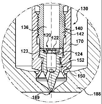
With reference to Figures 1 and 2 a non-limiting embodiment of a melt
distribution apparatus 110 for use in a hot runner is
shown. The melt distribution apparatus 110 includes a plurality of drops and a
plurality of chokes. Only a representative one
of a drop 112 and a choke 120 of the plurality of drops and the plurality of
chokes, respectively, are shown. As shown, the
representative choke 120 is associated with the representative drop 112.
Similarly, each choke 120 of the plurality of chokes
is associated with a corresponding one of a drop 112 of the plurality of
drops. Each choke 120 of the plurality of chokes is
configured to contribute, during an injection of a molding material
therethrough, a choke melt-pressure loss such that the
plurality of chokes contribute an aggregate choke melt-pressure loss that is
generally between 10% and 75% of an aggregate
hot runner melt-pressure loss. In further non-limiting embodiments, the
aggregate choke melt-pressure loss is generally
between 25% and 66%. In yet another non-limiting embodiment, the aggregate
choke melt-pressure loss is about 66% of the
aggregate hot runner melt-pressure loss of the hot runner. In so doing, the
aggregate choke melt-pressure loss overwhelms
any intrinsic melt-pressure imbalances between drops of the plurality of drops
wherein a technical effect of a more generally
balanced melt flow through the plurality of drops may be realized.
The melt distribution apparatus 110 may also include a plurality of nozzles.
As shown, each choke 120 of the plurality of
chokes is associated with a corresponding one of a drop 112 of a plurality of
drops. For sake of illustrating such a plurality
of nozzles, a further embodiment of a melt distribution apparatus 210 is shown
with reference to Figure 3. The melt
distribution apparatus 210 depicts quite clearly a typical arrangement of a
plurality of nozzles 131. Each nozzle 130 of the
plurality of nozzles 131 is configured to provide a nozzle portion of the
plurality of drops. Referring back to Figure 2, it is
shown that each nozzle 130 of the plurality of nozzles 131 includes a housing
member 140 and a tip member 150. A retainer
170 couples the tip member 150 to the housing member 140. The housing member
140 is configured to contribute, during
the injection of the molding material therethrough, a housing melt-pressure
loss. Likewise, the tip member 150 is configured
to contribute, during the injection of the molding material therethrough, a
tip melt-pressure loss. Accordingly, a nozzle melt-
pressure loss through each nozzle 130 of the plurality of nozzles 131 is a sum
of the housing melt-pressure loss, the tip
melt-pressure loss. The aggregate hot runner melt-pressure loss includes a
summation of each nozzle melt-pressure loss of
the plurality of nozzles 131.
In the non-limiting embodiment of Figure 3, the plurality of chokes is
associated with the plurality of nozzles 131.
Accordingly, the nozzle melt-pressure loss through each nozzle 130 of the
plurality of nozzles 131 further includes the
choke melt-pressure loss.
With reference to Figure 2, each choke 120 of the plurality of chokes may be
defined as a constricted melt channel 124 that
is defined in a choke body 122. Each choke 120 may be constructed from a
material that is compatible with the melt of
molding material. The material may include, for example, wear resistant
materials such as a ruby body, a diamond body, a
ceramic body, or a carbide body.
4
CA 02715264 2010-08-05
WO 2009/117285 PCT/US2009/036745
For best results, a deviation in the choke melt-pressure loss between chokes
of the plurality of chokes should be less than
about 1.5%. Ideally, the deviation should be less than 1.3%. The choke melt-
pressure loss of each choke 120 of the plurality
of chokes may be precisely established through careful manufacturing wherein
at least one of the length and diameter of the
constricted melt channel 124 is precisely controlled.
In the non-limiting embodiment of Figure 2, each choke 120 of the plurality of
chokes is arranged between the housing
member 140 and the tip member 150 of each nozzle 130 of the plurality of
nozzles 131. More particularly, each choke 120
is arranged in an adapter member 123 that is pressed into a seat defined in
the tip body 152, the seat positioned adjacent an
interface between the tip member 150 and the housing member 140. The
constricted melt channel 124 so arranged fluidly
couples a nozzle melt channel 136 that is defined, at least in part, through
the housing and tip members.
In a further non-limiting embodiment, not shown, each choke 120 of the
plurality of chokes may be arranged within one of
the housing member 140 and the tip member 150 of each nozzle 130 of the
plurality of nozzles 131.
In a further non-limiting embodiment, not shown, each choke 120 of the
plurality of chokes may be configured as a
constricted melt channel 124 that is defined on at least one of a housing body
142, of the housing member 140, and/or a tip
body 152, of the tip member 150. The constricted melt channel 124 fluidly
couples, in use, with a nozzle melt channel 136
that is defined, at least in part, in the housing body 142 and the tip body
152.
Referring back to the non-limiting embodiment of Figure 2, the melt
distribution apparatus 210 may further include a sprue
160, as is typical in a hot runner. The sprue 160 also contributes, during the
injection of the molding material therethrough,
a sprue melt-pressure loss. The aggregate hot runner melt-pressure loss
further includes the sprue melt-pressure loss.
Likewise, the non-limiting embodiments of the melt distribution apparatus 110,
210, 310 of any of Figures 1, 3, and a
further alternative embodiment of Figure 4 may further include a manifold 180
or 280. The manifold 180, 280 define a
network of melt channels (not shown) for connecting the sprue to the plurality
of drops. In the melt distribution apparatus
210 depicted in Figure 3, the manifold 180 is a collection of sub-manifolds
181, and 182. The particulars of construction
and operation of such a manifold 180, 280 is well known to the skilled reader
and hence will not be described further
herein. The manifold 180, 280 also contribute, during the injection of the
molding material therethrough, a manifold melt-
pressure loss. The aggregate hot runner melt-pressure loss further includes
the manifold melt-pressure loss.
In the non-limiting embodiments, a network of melt channels defined in the
manifold 180, 280 are geometrically balanced
(i.e. the dimensions of the melt channels connecting each drop to the sprue
are the same). However, in accordance with a
further non-limiting embodiment, not shown, at least a portion of the network
of melt channels between an inlet and the
plurality of drops may not be geometrically balanced.
The melt distribution apparatus 310 may further include a plurality of
manifold bushings. With reference to the non-limiting
embodiment of Figure 4, each manifold bushing 190 of the plurality of manifold
bushings may be associated with each drop
of the plurality of drops. Each manifold bushing 190 of the plurality of
manifold bushings are configured to provide a
bushing portion of the plurality of drops. Each manifold bushing 190 is
further configured to cooperate with a valve stem
apparatus 270. The valve apparatus 270 includes an actuator and a valve
member. The valve stem is operatively movable by
the actuator, in use, for controlling melt flow through each nozzle 230. The
particulars of construction and operation of such
5
CA 02715264 2010-08-05
WO 2009/117285 PCT/US2009/036745
a valve apparatus 270 is well known to the skilled reader and hence will not
be described further herein. Each manifold
bushing 190 is configured to contribute, during the injection of the molding
material therethrough, a bushing melt-pressure
loss. Accordingly, the aggregate hot runner melt-pressure loss further
includes a sum of each bushing melt-pressure loss of
the plurality of manifold bushings.
In the non-limiting embodiment, each choke 220 of the plurality of chokes are
associated with the corresponding manifold
bushing 190 of the plurality of manifold bushings. Accordingly, the bushing
melt-pressure loss through each manifold
bushing 190 of the plurality of manifold bushings would further include the
choke melt-pressure loss. More particularly,
each choke 220 of the plurality of chokes is arranged within each manifold
bushing 190 of the plurality of manifold
bushings. The constricted melt channel 124 fluidly couples with a bushing melt
channel 196 that is defined, at least in part,
in each manifold bushing 190.
In a further non-limiting embodiment, not shown, each choke 220 of the
plurality of chokes may be provided as a
constricted melt channel 224 that is defined on a bushing body 192 of each
manifold bushing 190 of the plurality of
manifold bushings. The constricted melt channel 224 fluidly couples with a
bushing melt channel 196 that is defined, at
least in part, by the bushing body 192.
While not shown in Figures 1 or 2, the melt distribution apparatus 110 may
also include a plurality of gate inserts. As
shown, each gate insert 188 of the plurality of gate inserts may be associated
with a corresponding one of each drop of the
plurality of drops in the melt distribution apparatus. Each gate insert 188 of
the plurality of gate inserts is configured to
define a gate portion of the plurality of drops. Each gate portion fluidly
couples, during the injection of the molding material
therethrough, each drop to a molding cavity (not shown) of a plurality of
molding cavities (not shown). The gate portion is
configured to contribute, during the injection of the molding material
therethrough, a gate melt-pressure loss.
In a further non-limiting embodiment, not shown, the plurality of chokes may
be associated with the plurality of gate inserts.
Accordingly, the gate melt-pressure loss through each gate insert 188 (i.e.
the gate portion thereof) of the plurality of gate
inserts would further include the choke melt-pressure loss, and likewise the
aggregate hot runner melt-pressure loss would
further include the gate melt-pressure loss.
In terms of the association of the plurality of chokes with the plurality of
gate inserts, it is possible that each choke 120 of
the plurality of chokes may be defined as a constricted melt channel 124 that
is defined in a choke body 122, as described
previously, and further that the choke body of each choke 120 is arranged in,
or adjacent, a gate melt channel 189 (i.e. gate
portion) of a corresponding gate insert 188 of the plurality of gate inserts.
Alternatively, it is possible that each choke 120 of
the plurality of chokes may be defined along at least a portion of the gate
melt channel 189. That is, the body that defines
the gate melt channel 189 also defines the constricted melt channel of the
choke - more particularly, the gate melt channel
189 and the constricted melt channel may be one and the same structure. The
foregoing requires that the combination gate
melt channel 189 and the constricuted melt channel (henceforth gate orifice)
is to be made more consistent and deliberately
than the current art advocates - recalling that for best results the deviation
between choke melt-pressure loss between
chokes of the plurality of chokes should not exceed 1.5%, and more ideally,
that the deviation should be less than 1.3%. Put
differently, if the components of the gate orifice (i.e. gate diameter and/or
land) are constructed such that each gate orifice
induces substantially the same melt-pressure loss, then the mold balance will
be improved.
6
CA 02715264 2010-08-05
WO 2009/117285 PCT/US2009/036745
As shown in any of the non-limiting embodiments of Figures 1, 2, or 4, the
constricted melt channel 124, 224 is defined as a
single cylindrical channel. The configuration of the constricted melt channel
124, 224 is however not so limited in terms of
shape or in number (i.e. could be one or more cylindrical channels). For
example, in a further non-limiting embodiment, not
shown, the form of the constricted melt channel may be defined in the form of
a slot, a slit, or an annular orifice.
In yet another non-limiting embodiment, the melt plurality of chokes may
include a first subset having an adjusted choke
melt-pressure loss that is different than the choke melt-pressure loss of a
remainder of the plurality of chokes. So
configured, the plurality of drops of the hot runner may have an intentional,
but controlled, melt flow imbalance.
Details of an Experimental Melt Distribution Apparatus
The inventors built and tested an experimental hot runner (not shown) that
included the melt distribution apparatus 110 of
Figure 1. The experimental hot runner had four drops, each drop including a
U500 HT nozzle from Husky Injection
Molding Systems Limited (ywvw.huskv.ca). Each nozzle defined a nozzle melt
channel 136 that was 5 mm in diameter. The
experimental hot runner was coupled to a 4 cavity closure mold (not shown).
Various chokes were tested in combination
with the nozzles. Each choke 120 in the experimental hot runner were provided
by a 'precision orifice' from Bird Precision,
Inc (www.birdrsrecisiou_corca). One such 'precision orifice' tested had a
constricted melt channel 124 provided as a single
cylindrical channel with a diameter of 0.635 mm (0.025 inch) and a length of
0.660 mm (0.026 inch) that was defined in a
ruby body. The results from a representative set of tests showed an
improvement in the melt flow imbalance from about
85%, when testing without the 'precise orifices' installed, to about 89%, with
the 'precision orifice' installed in each nozzle.
Accompanying the foregoing test was an increase in injection pressure from
103.4 MPa (15,000 PSI) to 172.37 MPa
(25,000 PSI).
Other configurations of the foregoing 'precision orifice' tested included
those having a single cylindrical channel of sizes
ranging from 0.254 mm (0.010 inch) to the afore mentioned 0.635 mm (0.025
inch). In each test the melt flow imbalance
between the drops was significantly improved. With the smaller orifice sizes
there is an associated requirement of increasing
injection pressure. Accordingly, the choke body 122 may be made longer to
increase the integrity thereof and thereby
handle the higher injection pressure.
Method of Balancing Melt Flow
Related to the foregoing is a method for balancing melt flow to a plurality of
drops of a melt distribution apparatus, such as
may be practised, for example, with the non-limiting embodiments of the melt
distribution apparatus 110, 210, 310
discussed previously. The method includes injecting a molding material through
the melt distribution apparatus 110, 210,
310, and further choking the plurality of drops thereby introducing an
aggregate choke melt-pressure loss that is generally
between 10% and 75% of an aggregate hot runner melt-pressure loss. In so
doing, the aggregate choke melt-pressure loss
overwhelms any intrinsic melt-pressure imbalances between drops of the
plurality of drops wherein a technical effect of a
more generally balanced melt flow through the plurality of drops may be
realized.
In accordance with another non-limiting embodiment, the method is similar to
the foregoing however the choking of the
plurality of drops introduces the aggregate choke melt-pressure loss that is
generally between 25% and 66% of the
aggregate hot runner melt-pressure loss of the hot runner.
7
CA 02715264 2010-08-05
WO 2009/117285 PCT/US2009/036745
In accordance with another non-limiting embodiment, the method is similar to
the foregoing however the choking of the
plurality of drops introduces the aggregate choke melt-pressure loss that is
about 66% of the aggregate hot runner melt-
pressure loss of the hot runner.
In accordance with another non-limiting embodiment, the method is similar to
the foregoing however the choking of the
plurality of drops introduces a deviation in a choke melt-pressure loss
between drops of the plurality of drops that is less
than about 1.5%.
In accordance with another non-limiting embodiment, the method is similar to
the foregoing however the choking of the
plurality of drops introduces a deviation in a choke melt-pressure loss
between drops of the plurality of drops that is less
than about 1.3%.
Method for Configuring a Melt Distribution Apparatus
Also related to the foregoing is a method for configuring a melt distribution
apparatus of a hot runner for use in an injection
molding system, such as, for example, the non-limiting embodiments of the melt
distribution apparatus 110, 210, 310
discussed previously. The method includes providing a plurality of chokes,
each choke of the plurality of chokes being
associated with a corresponding one of a drop of a plurality of drops. In
addition, the method includes configuring each
choke of the plurality of chokes to contribute, during an injection of a
molding material therethrough, a choke melt-pressure
loss such that the plurality of chokes will contribute an aggregate choke melt-
pressure loss that is generally between 10%
and 75% of an aggregate hot runner melt-pressure loss. In so doing, the
aggregate choke melt-pressure loss overwhelms any
intrinsic melt-pressure imbalances between drops of the plurality of drops
wherein a technical effect of a more generally
balanced melt flow through the plurality of drops may be realized.
The method may further include flow testing each of the choke 120, 220 of the
plurality of chokes to determine an actual
choke melt-pressure loss therethrough. And, in addition, adjusting any of the
choke 120, 220 of the plurality of chokes with
the actual choke melt-pressure loss therethrough being outside a first
predetermined range of choke melt-pressure loss. In so
doing, balancing of the choke melt-pressure loss through each choke 120, 220
of the plurality of chokes is provided.
Likewise, the method may include further flow testing each of the choke 120,
220 of the plurality of chokes to determine a
corrected choke melt-pressure loss therethrough. And, in addition, further
adjusting any of the choke 120, 220 of the
plurality of chokes with the corrected choke melt-pressure loss therethrough
being outside a second predetermined range of
choke melt-pressure loss, wherein the second predetermined range of choke melt-
pressure loss is smaller than the first
predetermined range of choke melt-pressure loss. . In so doing, balancing of
the choke melt-pressure loss through each
choke 120, 220 of the plurality of chokes is further improved.
The adjusting any of the choke 120, 220 of the plurality of chokes may
include, for example, modifying the geometry of a
constricted melt channel 124, 224 thereof.
Description of the embodiments of the present inventions provides examples of
the present invention, and these examples
do not limit the scope of the present invention. It is to be expressly
understood that the scope of the present invention is
limited by the claims. The concepts described above may be adapted for
specific conditions and/or functions, and may be
further extended to a variety of other applications that are within the scope
of the present invention. Having thus described
8
CA 02715264 2010-08-05
WO 2009/117285 PCT/US2009/036745
the embodiments of the present invention, it will be apparent that
modifications and enhancements are possible without
departing from the concepts as described. Therefore, what is to be protected
by way of letters patent are limited only by the
scope of the following claims:
9