Note : Les descriptions sont présentées dans la langue officielle dans laquelle elles ont été soumises.
CA 02715339 2013-12-06
A
VEHICLE MOUNTED IMPLEMENT MOVEMENT
CONTROL APPARATUS AND METHODS
BACKGROUND
An implement mounting and movement control apparatus, in embodiments,
mountable to vehicles such as tractors (regardless of size), is disclosed.
Typical
applications include control of movement of graders, brooms, rippers, core
plug aerators,
dethatchers, and landscape rakes, as but a few examples.
Conventional implement mounting structures have been heavy and hard to
install.
Attachments were difficult to change, which was labor intensive, time
consuming, and
required many tools. Complex attachment and implement movement control systems
have
compromised durability and caused high purchase and repair costs.
The inventive technology disclosed herein, in embodiments, mitigates one or
more of
these drawbacks. For example, installation, and removal, is comparatively
facile and fast.
Attachments, (grader blade, broom, core plug aerator, dethatcher, or landscape
rake, as but
a few examples), in particular embodiments, may have just two attachment
points (e.g.,
threaded bolts and nuts. etc.). Further, in particular embodiments, the entire
unit, except
for the mounting brackets and the rear support bracket, can be removed by
disconnecting
hydraulic quick couplings and removing a few pins. Further, mounting brackets
do not
interfere with operation of the tractor or a front end loader and can remain
on the tractor.
The disclosed technology, in embodiments, is light weight in comparison to
many previous
apparatus. It offers a simple, robust solution to the problem of multi-degree
of freedom
movement control of a vehicle attached implement. In embodiments, the
inventive
technology is capable of implement lift/lower, implement fore/aft movement,
enhanced
CA 02715339 2013-12-06
implement pitch, implement tilt, and also implement side to side movement
(known as side
shift). Other objects and advantages may be described elsewhere in the
application,
including in the following description and the figures. The following figure
descriptions,
and the figures themselves, are exemplary only and should not be used to limit
the
inventive technology in any manner.
In accordance with an aspect of the present invention, there is provided a
vehicle supported
implement control apparatus for connection with a vehicle having a vehicle
chassis and
movable in a vehicle forward travel direction, said apparatus comprising: a
mounting
component that is stationary relative to said vehicle chassis; a shaft that is
pivotally
connectable with said mounting component so that, during apparatus operation,
said shaft is
rotatable relative to said mounting component only about an implement lift and
lower axis
about which an implement assembly may be raised and lowered, wherein said
implement lift
and lower axis is orthogonal to a vehicle forward travel direction; at least
one structural
component other than said shaft that, during said apparatus operation, is
rotatable only about
said implement lift and lower axis; wherein said shaft defines an implement
tilt axis that
passes along the length of said shaft, wherein said implement tilt axis is
orthogonal to said
implement raise and lower axis, said implement tilt axis defining right and
left vehicle
portions, a movable frame that, during said apparatus operation, is movable
relative to said at
least one structural component only through rotation about said implement tilt
axis, wherein
said shaft passes through at least part of said movable frame, and wherein
said movable frame
has right, left, front and rear movable frame portions; said apparatus further
comprising: a
first pair of actuators, each having two ends, each connected at one end with
said right and
left vehicle portion, respectively, and at an opposite end with said right and
left movable
frame portion, respectively; an implement assembly pivotally connected with
said movable
frame so that during said apparatus operation, said implement assembly is
rotatable relative to
an implement yaw axis that is substantially orthogonal to said implement tilt
axis, said
implement assembly having right and left implement assembly portions; and a
second pair of
actuators, each having two ends, each connected at one end with said right and
left movable
frame portion, respectively, and at an opposite end with said right and left
implement
assembly portions, respectively.
2
CA 02715339 2013-12-06
_
In accordance with a further aspect of the present invention, there is
provided a method for
controlling a position of a vehicle supported implement comprising the steps
of: operating a
first pair of actuators to pivot a shaft and at least one structural component
other than said
shaft about a horizontal axis that is orthogonal to a vehicle forward travel
direction in order to
control height of an implement assembly above an underlying ground surface,
said shaft and
said at least one structural component rotatable only about said horizontal;
operating said first
pair of actuators to rotate a movable frame about an axis along the length of
said shaft,
thereby controlling a tilt orientation of said implement assembly; while
performing said step
of operating said first pair of actuators to rotate a movable frame about an
axis along the
length of said shaft, rotating said movable frame relative to said at least
one structural
component; operating a second pair of actuators to controllably change an
angle said
implement makes with a forward travel direction of the vehicle supporting said
implement;
and operating an enhanced implement pitch controller to control a pitch
orientation of an
implement of said implement assembly without affecting spatial positions of
any of said
actuators of said first and second pairs of actuators.
BRIEF DESCRIPTION OF THE FIGURES
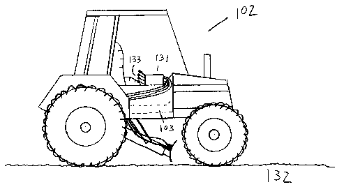
Fig. lA shows a side view of a tractor with the one embodiment of the
apparatus belly
mounted thereto. The apparatus is shown in only a very skeletal manner for
clarity.
Fig. 1B shows a front view of a tractor with the one embodiment of the
apparatus belly
mounted thereto. The apparatus is shown in only a very skeletal mariner for
clarity. The
second axis is shown as a vertical line because of the angle it makes with the
ground
surface when the implement is near, at or below grade (ground level).
Fig. 2 shows a sketch of the movable frame and various attached components, in
addition
to axes of rotation/translation, in at least one embodiment of the inventive
technology.
Actuators are deleted for clarity reasons.
2a
CA 02715339 2013-12-06
_
= I
Fig. 3 shows a sketch of the movable frame and various attached components, in
addition
to axes of rotation/translation and actuators, in at least one embodiment of
the inventive
technology.
Fig. 4A shows a schematic of a view from above the implement (a grading blade
in this
instance), showing in particular the fore/aft angling motion degree of freedom
afforded by
embodiments of the inventive technology.
Fig. 4B shows a schematic of a view from in front of (or behind) the implement
(a grading
blade in this instance), showing in particular the tilting motion degree of
freedom afforded
by embodiments of the inventive technology.
2b
CA 02715339 2010-09-21
Fig. 4C shows a schematic of a view from the side of the implement (a grading
blade in this
instance), showing in particular the raising/lowering motion degree of freedom
afforded by
embodiments of the inventive technology. As this degree of freedom is, in
preferred
embodiments, accomplished via rotation about the first axis, it is most
accurately be
described as a rotational raising/lowering motion degree of freedom.
Fig. 4D shows a schematic of a view from the side of the implement (a grading
blade in
this instance), showing in particular enhanced pitch motion degree of freedom
of the
implement afforded by embodiments of the inventive technology.
=
Fig. 4e shows a schematic of a view from in front of (or behind) the implement
(a grading
blade in this instance), showing in particular the right/left sliding motion
degree of freedom
afforded by embodiments of the inventive technology.
Fig. 5 shows a perspective view (from the rear looking forward, at an angle)
of an
embodiment of the inventive apparatus.
Fig. 6 is a top view looking down view of an embodiment of the inventive
apparatus,
illustrating the implement mounting structure with the grading attachment
installed.
Fig. 7 is a detailed side view of an embodiment of the inventive apparatus,
illustrating the
implement mounting structure with the grading attachment installed.
Fig. 8 is a perspective view of the rear support bracket and the two mounting
plates that may be
attached (e.g. welded, etc.) to the tractors rear hitch assembly in an
embodiment of the
inventive apparatus. As such, it is merely one of many examples of components
that may be
used to accomplish the necessary connection.
3
=
CA 02715339 2010-09-21
Fig. 9 is a detailed view of the tractor mounting bracket that is attached to
the tractor, in an
embodiment of the inventive apparatus. Also shown is the rear bushing used to
mount the
lift/lower bracket in an embodiment of the inventive apparatus.
Fig. 10 is a detailed view of the upper tilt actuator mounting bracket, in an
embodiment of the
inventive apparatus.
Fig. 11 is a detailed view of the lift/lower tilt bracket showing the front
lift/lower bushings and
the rear tilt bushing in an embodiment of the inventive apparatus.
Fig. 12 is a perspective view looking down at the movable frame (e.g., tilt
and fore/aft
assembly) showing a partial view of shaft that runs through the it (e.g.,
through the rear tilt
bracket, the sizing bushing and the front tilt bracket and the front tilt
bushing) in an
embodiment of the inventive apparatus. FIG 12 also shows the rear fore/aft
actuator
mounting brackets, the lower tilt actuator bracket and the rear fore/aft hitch
bracket in an
embodiment of the inventive apparatus.
Fig. 13 is a perspective view of the sizing bushing, and a partial view of the
shaft that runs
through the rear tilt bushing, the sizing bushing, and the front tilt bushing
in an
embodiment of the inventive apparatus.
Fig. 14 is a perspective view of lower tilt bracket in an embodiment of the
inventive
apparatus.
Fig. 15 is an underside perspective view of the front fore/aft hitch mounting
bar (for
movement of the implement about the yaw axis) showing the mounting holes for
the left
and right actuators, the rear left and right mounting brackets and bushings
for the front
pitch and attachment bar, the bushings for the hitch pivot, the mounting
brackets for the
rear side shift actuator mounts and the rear pitch mount in an embodiment of
the inventive
apparatus.
4
CA 02715339 2014-08-07
T
%
Fig. 16 is an underside perspective view of the rear pitch actuator mount
showing the
spacer that is attached (e.g.,welded, etc.) to front fore/aft hitch mounting
bar, and the rear
pitch actuator brackets in an embodiment of the inventive apparatus.
Fig. 17 is a perspective view of the front pitch and attachment bar showing
the side shift
bar, the sliding side shift bracket, the side shift actuator mounts, the front
left and right
pitch mounting brackets and bushings, the front pitch actuator mount spacer,
the front
pitch actuator mount, the front pitch actuator brackets, the attachment
bracket joined (e.g.,
welded, etc.) to the sliding side shift bracket, and the attachment bracket
holes in an
embodiment of the inventive apparatus.
Fig. 18 is a perspective view of the attachment bracket showing the attachment
holes used
to mount (e.g. threaded bolts and nuts) the various attachments in an
embodiment of the
inventive apparatus.
Fig. 19 is a perspective view of the blade attachment embodiment showing the
holes that
are used to attach (e.g., threaded bolts and nuts, etc.) to the attachment
bracket and the
cutting edge attached (e.g., welded, threaded bolts and nuts, etc.) in an
embodiment of the
inventive apparatus.
Fig. 20 shows a flow chart of the hydraulics used in particular embodiments.
CA 02715339 2014-08-07
Fig. 21 shows a lift/lower (also known as raise lower) tilt bracket as may be
found in an
embodiment of the inventive technology. Dimensions are merely exemplary, and
certainly
not limiting in any fashion (this applies to all disclosure of dimensions in
this description,
including drawings).
Fig. 22 shows a lift/lower (also known as raise lower) tilt bracket as may be
found in an
embodiment of the inventive technology.
Figs. 23 A-C show a movable frame as may be found in an embodiment of the
inventive
technology.
Figs. 24 A-C show a fore and aft bracket as may be found in an embodiment of
the
inventive technology.
Figs. 25A-C show an enhanced implement pitch bracket as may be found in an
embodiment of the inventive technology.
Figs. 26 A-C show a slide carriage and related componentry as may be found in
an
embodiment of the inventive technology.
Fig. 27 shows mounting componentry as may be found in an embodiment of the
inventive
technology.
DESCRIPTION OF PREFERRED EMBODIMENTS
As mentioned earlier, the present invention includes a variety of aspects,
which may be
combined in different ways. The following descriptions are provided to list
elements and
describe some of the embodiments of the present invention. These
6
CA 02715339 2010-09-21
elements are listed with initial embodiments, however it should be understood
that they
may be combined in any manner and in any number to create additional
embodiments.
The variously described examples and preferred embodiments should not be
construed to
limit the present invention to only the explicitly described systems,
techniques, and
applications. Further, this description should be understood to support and
encompass
descriptions and claims of all the various embodiments, systems, techniques,
methods,
devices, and applications with any number of the disclosed elements, with each
element
alone, and also with any and all various permutations and combinations of all
elements in
this or any subsequent application.
In certain embodiments, a hydraulically operated, belly-mounted implement
attachment for tractors (compact utlility tractors, as but one example).
Facile and fast
attachment and detachment, absence of interference with other attachments,
simplicity of
operation, responsiveness, strength, and lower weight as compared with certain
prior art
apparatus are just a few of the many advantages offered by the inventive
technology
described herein, in embodiments.
At least one embodiment of the inventive technology may be described as a
vehicle supported implement control apparatus 101 for connection with a
vehicle 102
having a vehicle chassis 103 (a supporting frame) and movable in a vehicle
forward
travel direction 104. The apparatus may comprise a mounting component 105 that
is
stationary relative to the vehicle chassis (it may be considered part of the
vehicle); and a
movable frame 30 pivotally connectable with the mounting component so that the
movable frame is rotatable relative to the mounting component about a first
axis 106
(which, in at least one embodiment, is horizontal) that is orthogonal to a
vehicle forward
travel direction; the movable frame may have right, left, front and back
movable frame
portions 107, 108, 109, 110.
The apparatus may further include a shaft 21 passing through at least a part
of the
movable frame and defining a second axis 113 that is transverse to the first
axis and about
which the frame is rotatable; a first pair of actuators 114, each having two
ends, each
7
CA 02715339 2010-09-21
=
connected at one end with the right and left vehicle portion, respectively,
and at an
opposite end with the right and left movable frame portion, respectively; an
implement
assembly 115 (which may include an implement such as a grading blade (62), as
but one
example) pivotally connected with the movable frame so that the implement
assembly is
rotatable relative to a third axis 116 that is substantially orthogonal to the
first and the
second axes, the implement assembly having right and left implement assembly
portions
117, 118; and a second pair of actuators 119, each having two ends, each
connected at
one end with the right and left movable frame portion, respectively, and at an
opposite
end with the right and left implement assembly, respectively. The right
vehicle portion
111 may be on a right side of the first axis and the left vehicle portion 112
on a left side
of the first axis.
In preferred embodiments, the vehicle supported implement is a tractor
supported
implement; it may, more particularly, be a tractor belly mounted implement
(such as a
grading blade). The apparatus may more generally be used whenever it is
desired to
control the position of a first element (e.g., an implement) in relation to a
second element
(e.g., a vehicle of any sort) to which it is attached. In at least one
embodiment, the first
axis is an implement raise and lower axis; the second axis is an implement
roll axis;
and/or the third axis is an implement yaw axis. Of course, such terms can be
understood
upon analogy to their meanings in an aeronautical context (from a perspective
above the
vehicle carrying the implement, where forward is a forward vehicle travel
direction). In
particular embodiments, the movable frame is movable only relative to the
first and
second axes (e.g., an implement raise and lower axis and an implement yaw
axis).
In at least one embodiment, the implement assembly (which, of course, may
include an implement) may also comprise a right left implement movement
controller
123 that translationally moves the implement in left and right directions 126,
127 along a
translation axis 128. In preferred embodiments, operation of the right left
implement
movement controller does not effect change in spatial position of the movable
frame. In
embodiments with a right left implement movement controller (and even in some
without), the implement assembly may be movable in at least four degrees of
freedom
8
CA 02715339 2010-09-21
(perhaps at least two degrees of freedom relative to the movable frame). The
apparatus
may further include an enhanced implement pitch controller connected with the
implement assembly, perhaps enabling movement of the implement assembly in
five
degrees of freedom (perhaps three degrees of freedom relative to the movable
frame).
In certain embodiments, the right left implement movement controller is a
right
left implement movement actuator 129 (e.g., a hydraulic cylinder, or a lever).
In at least
one embodiment, the right left implement movement controller has two ends and
is
connected with the implement at a first of the two right left implement
movement
controller ends. The implement assembly may further include a non-implement
portion
120, and the other of the two right left implement movement controller ends
may be
connected with the non-implement portion of the implement assembly. In certain
preferred embodiments, the right left implement movement controller slidingly
moves the
implement relative to the movable frame along the translation axis. The
implement
assembly may further comprise a slide carriage 50 with which the implement is
slidingly
engaged.
At least one embodiment of the inventive technology may further include an
enhanced implement pitch controller 121 connected with the implement assembly.
Preferably, operation of the enhanced implement pitch controller does not
effect change
in spatial position of the movable frame. Also, the enhanced implement pitch
controller
may rotabably move the implement about an enhanced pitch axis 122 that is more
proximal the implement than is the first axis and that is orthogonal to the
third axis. In
certain embodiments the enhanced pitch axis is forward of a rearward most
portion of the
implement assembly; the enhanced pitch axis may be parallel with the first
axis. In such,
and other embodiments, the implement assembly may be movable in at least 4
degrees of
freedom; it may be movable in at least two degrees of freedom relative to the
movable
frame. In such, and other, embodiments, the implement assembly may comprise a
right
left implement movement controller 123 that translationally moves the
implement in left
and right directions. The implement assembly may include a mechanism 128
enabling
rotation of the implement about an enhanced pitch axis. The term enhanced, as
used
9
CA 02715339 2010-09-21
here, refers to pitch motion that is defined by a smaller radius of curvature
than motion
about an implement raise and lower axis (which also may be viewed as a type of
pitch
motion). As such, low resolution pitch control may be achieved up manipulation
of the
implement assembly about the implement raise and lower axis, and higher
resolution
control may be achieved upon manipulation of the implement assembly about the
enhanced pitch axis.
In embodiments with an enhanced implement pitch controller, it may include an
enhanced implement pitch actuator 124 (e.g., a hydraulic cylinder 125, or a
lever). In
particular embodiments, the enhanced implement pitch controller has two ends
and is
connected with an implement of the implement assembly at one of the two
enhanced
implement pitch controller ends. The other of the two enhanced implement pitch
controller ends may be connected with the movable frame.
In certain embodiments, the first pair of actuators is operable to effect
rotatable
movement of the movable frame about the first axis and the second axis, and
the second
pair of actuators is operable to effect rotatable movement of the implement
assembly
about the third axis. The second pair of actuators may be operable to effect
rotatable
movement of the implement assembly about the third axis without moving the
movable
frame. Further, motion about the first axis may effect a change in spatial
position of the
second pair of actuators, and motion about the second axis may effect a change
in spatial
position of the first pair of actuators. In certain embodiments, as may be
clear, the
implement assembly may be movable relative to the movable frame.
Additionally, with regard to connections in certain embodiments, two ends
(e.g.,
rearward ends) of the first pair of actuators may be connected with the right
and left
vehicle portions and may be connected above the first axis. Further, two ends
(e.g.,
rearward ends) of the second pair of actuators may be connected with the right
and left
movable frame portion and may each be connected closer to the second axis than
are the
ends of the second pair of actuators that are connected with the right and
left implement
assembly portions.
CA 02715339 2010-09-21
In certain embodiments, the apparatus may further include a manually operable
hydraulic control system 131 to which the actuators are responsive. Actuators
may
instead be pneumatic, e.g., or indeed may be any type of powered (often, but
not
necessarily, to achieve a necessary fluidic pressure) system. Actuators may be
activated
by manually operable handles 133 of the hydraulic control system. Instead, in
a non-
powered control system, the actuators may include manually operated levers 134
and
position locks 135, in addition, perhaps, to springs that bias implement
position relative
to an axis in a certain direction, whether translational or rotational.
In certain embodiments, the apparatus may further include a bushing 34
established around at least a portion of the shaft Further, the movable frame
may include
rear and front support portions, and an intermediate support 71 between the
front and
back movable frame portions 109, 110. The movable frame may define two
polygons 72,
which, as but one example, may be two rectangles 73 and/or may share a common
side
74.
Particular embodiments of the inventive technology may relate to a method for
controlling a position of a vehicle supported implement, and may include the
steps of:
operating a first pair of actuators to control height of an implement assembly
above an
underlying ground surface 132 while simultaneously controlling the height of a
movable
frame to which the implement assembly is attached; operating the first pair of
actuators to
control a tilt orientation of the implement assembly; operating a second pair
of actuators
to controllably change an angle the implement makes with a forward travel
direction of
the vehicle supporting the implement; and operating an enhanced implement
pitch
controller to control a pitch orientation of an implement of the implement
assembly
without affecting spatial positions of any of the actuators of the first and
second pairs of
actuators. Inventive methods may further include the step of working
underlying
material (e.g., soil, gravel, etc.).
11
CA 02715339 2010-09-21
The method may further include the step of operating a right left implement
movement controller to translationally move the implement in left and right
directions
along a translation axis without affecting spatial positions of any of the
actuators of the
first and second pairs of actuators or of the enhanced implement pitch
controller. The
step of operating a second pair of actuators to controllably change an angle
76 a
longitudinal axis 88 of the implement makes with a forward travel direction of
the vehicle
supporting the implement may include the step of operating a second pair of
actuators to
controllably change an angle the implement longitudinal axis makes with a
forward travel
direction of the vehicle supporting the implement without changing an angle an
implement tilt axis 77 makes with the forward travel direction of the vehicle
supporting
the implement. Further, the step of operating the first pair of actuators to
control a tilt
orientation of the implement assembly may comprise the step of operating the
first pair of
actuators to rotate the movable frame about a shaft 21 passing therethrough,
which itself
may involve the step of operating the first pair of actuators to rotate the
movable frame
about a shaft having a bushing 34 established therearound.
The step of operating the first pair of actuators to rotate the movable frame
may
include the step of operating the first pair of actuators to rotate a movable
frame that
includes front and rear support portions 109, 110 and an intermediate support
therebetween. It may include the step of operating the first pair of actuators
to rotate a
movable frame that defines two polygons 72 (e.g., two rectangles 73, which may
or may
not share a common side 74).
The steps of operating may each comprise the step of hydraulically operating
through manual manipulation of handles 133. The steps of operating may instead
each
comprise the step of manually operating through levers and position locks
(using known
lever-type technology). Further, the step of operating a second pair of
actuators to
controllably change an angle the implement makes with a forward travel
direction of the
vehicle may include the step of operating a second pair of actuators without
affecting
spatial positions of any of the first pair of actuators.
12
CA 02715339 2010-09-21
It is of note that any part or portion of the apparatus or vehicle to which it
may be
mounted that it stationary and not movable relative to the vehicle (via the
implement
control apparatus) may be considered a part of that vehicle, even if the part
or portion is
added to the vehicle specifically to allow for connection of the implement
control
apparatus to the vehicle. A mounting component for the apparatus may be a part
of the
vehicle; where it is stationary relative to vehicle chassis it is considered
part of the
chassis also.
This description should be viewed as disclosing not only a connectible
apparatus
(i.e., an apparatus connectible to vehicle), but also a connected apparatus.
Indeed, all
functionally descriptive terms (attachable, connectible, etc.) should be
considered as also
providing support for the referenced parts and components as if the function
were
achieved (attached and connected, e.g.).
The term "each connected at one end to the right and left vehicle portion,
respectively" implies that one of the referenced components is connected with
the right
vehicle portion and the other to the left vehicle portion (similarly worded
phrases and
limitations have analogous meanings). It is of note that the term right and
left, forward
and rearward are relative to driver sitting in the vehicle; forward is the
forward direction
of travel defined by the vehicle itself.
More particularly with regard to certain motions and axes thereof, the term
implement axis (roll axis, raise and lower axis) might also be a movable frame
axis in
that the indicated motion (roll or raise and lower) might also be seen in the
movable
frame. In certain embodiments, the first pair of actuators can effect motion
about the first
axis and/or the second axis. Further, it is of note that the term "rotatable"
applies even
where the referenced component is only partially rotatable about an axis.
It is also of note that even where the enhanced implement pitch controller is
connected with the movable frame such that it does not intersect the third
axis (which
may be a yaw axis), operation of the enhanced implement pitch controller to
effect
13
CA 02715339 2010-09-21
enhanced yaw movement of the implement should not effect a yaw movement of the
implement or implement assembly because it will typically not be offset from
the third
axis enough to do so (more particularly, only a relatively small moment should
be
generated during operation of the enhanced implement pitch controller).
Further, the
second pair of actuators (connected with the implement assembly much further
out from
the third axis than the connection point of the enhanced implement pitch
controller) may
act to counter such yawing motion (particularly when not being operated to
change a yaw
position of the implement assembly). Of course, off-axis establishment of the
connection
of the enhanced implement pitch controller is not a necessary feature of the
invention.
Further, and more particularly with regard to certain components, anything
that is
stationary relative to the implement during all its different types of motion
may
considered part of the implement. At times, the implement assembly may include
only
the implement itself. Any actuator may be, in one preferred embodiment, a
hydraulic
cylinder. Further, certain portions of the shaft can be extended (e.g., the
rearward most
portion), typically at or during apparatus installation, with the frame
adjusted to
compensate to allow for extension to provide a customized fit of the apparatus
into a
particular tractor. This is one manner in which the apparatus may be adjusted
to fit onto
different sized vehicles (tractors, e.g.). One other manner includes
incorporation of an
appropriately sized mounting component to situate the rest of the apparatus as
desired
(e.g., in the "belly" position of a tractor). In certain embodiments, the
first pair of
actuators is the only pair that has an end that is stationary relative to the
vehicle chassis.
Further, actuators can be entirely lever controlled (can be position lockable)
actuators.
Particularly when they are powered (e.g., hydraulically to provide
pressurization of a
working fluid), they may be extendable (e.g., when an actuator is a hydraulic
cylinder). It
is also of note that the term right and left vehicle portions are not
necessarily defined by
the centerline (along the direction of travel) of the vehicle; instead, more
particularly,
they are defined by the implement roll axis (which may be the second axis).
As follows are specification details regarding at least one embodiment of the
inventive technology. Such following description, and the figures referenced
therein,
14
CA 02715339 2010-09-21
show an exemplary manner(s) in which the apparatus may be constructed.
Generally, the
following presents connection merely embodiments or examples of the many many
various types of attachment and connection componentry that may be used.
Because
details regarding all components may be described in the following (and in the
figures
that it references), referenced parts may be called out using rather specific
names. Of
course, at times the specific names given may be types of certain more generic
names
already given to such parts. As follows:
11- Rear support bracket
12 - Mounting Plates
14 ¨ Tractor Mounting Bracket
15 ¨ Rear Lift/Lower Bushing
16 ¨ Upper Tilt Lift/ Lower Actuator Mount
17¨ Lift/Lower Tilt Bracket
18 ¨ Tilt Bushing
19 ¨ Left and Right Front Lift/Lower Bushing
21- Solid shaft (e.g., used for pins in lift lower and tile assemblies, and
perhaps also pivot and pitch
assemblies)
30 ¨Movable Frame (e.g., Tilt Lift/Lower and Fore/Aft Assembly)
32 ¨ Rear Left and Right Fore/Aft Actuator Brackets
34- Sizing Bushing
35 ¨ Front Tilt Bushing
36 ¨ Fore/Aft Hitch Bracket
38 ¨ Rear Hitch Pivot Bushing
39 ¨ Lower Tilt Lift/Lower Actuator Bracket
40¨ Fore/Aft Pivot Bar
41 ¨ Holes for Front Fore/Aft Actuator Pins
42 ¨ Left and Right Mount for Pitch Bracket
43 ¨ Left and Right Rear Pitch Attachment Bushing
44- Front Hitch Pivot Bushings
45 ¨Rear Side Shift Actuator Mounts
,
CA 02715339 2010-09-21
46- Rear Pitch Actuator Mount Spacer
47- Rear Pitch Actuator Mounting Bracket
48- Rear Pitch Actuator Mounts
50 ¨ Slide Carriage (e.g., Sliding Side Shift Bracket
51 ¨ Attachment Mounting Bracket
53 ¨Front Side Shift Actuator Mount
54 ¨ Front Left and Right Side Attachment Mounting Bracket
55 ¨ Front Left and Right Side Attachment Mounting Bushing
57- Front Pitch Actuator Mount Spacer
58- Front Pitch Actuator Mount
59 ¨ Front Pitch Actuator Mounting Brackets
60- Attachment Mounting Bracket
61- Attachment Mounting Bracket holes
62 ¨ Grader Blade
63- Grader Blade Attachment holes
64- Grader Blade Attachment cutting edge
Rear Support bracket 11 may be mounted to the Rear Support Mounts which may
be welded to the Tractor hitch mount. Bracket 11 may then be welded to the
Tractor
Mounting Bracket 14. In the embodiment shown Bracket 14 and the upper tilt,
lift/lower
actuator mount bracket 16 attach to the tractor. Other embodiments could
include a plate
of steel mounted to the tractor that is then mounted to 14 (as but one
example). The rear of
the lift/lower assembly 17 may be pivotally attached (e.g., pinned, bolted,
etc.) to 12
through bushings 19 and 15. The front of 17 may be pivotally attached (e.g.,
pin, bolt, etc.)
by pin 21 to the tilt lift/lower and fore/aft assembly 30 through the rear
tilt bushing 18,
sizing bushing 34, and tilt lift/lower and fore/aft assembly stabilizer
bushing 35. Rear
fore/aft actuator mounting brackets 32 may be attached (e.g., welded, etc.) to
30.
Fig. 13 shows the sizing bushing 34 and Pin 21. The bushing material used
throughout
this embodiment may be the same diameter. The lengths may vary depending on
the
application. Pin 21 may be used as a solid round shaft and lengths may vary
depending on
16
CA 02715339 2010-09-21
the application. The pins used in the Lift/Lower bushings-15&19, the Tilt
bushings-
18&35, Sizing Bushing 34, the Hitch Pivot Bushings-38&44, and the Attachment
Bushings-43&55 are the same diameter as 21.
Lower tilt lift/lower actuator bracket 39 may be centered side to side on the
top side
of fore/aft assembly 30. Bracket 39 may be attached (e.g., welded, etc.) to 30
at the highest
point of the actuators travel, assuring clearance of all components on the
underside of the
tractor (hydraulic lines, brake levers, etc.). Fore/aft hitch 36 may be
centered on the front
of 30 and attached (e.g. welded, etc.). Fore/aft hitch bushing 38 may be
centered
horizontally and positioned near the front edge of 36.
Fore/aft mounting bar 40 may be attached (e.g. pinned, etc.) to 30 through 38.
Top
and bottom fore/aft mounting bar bushings 44 may be centered left to right on
40 and
attached near the rear top and bottom of 40.
Holes 41 may be used for mounting the fore/aft actuators on the left and right
side
of 40. Holes 41 may be spaced at a distance from the center hole of 40 such
that the
fore/aft movement of 40 and/or attachments will not hit any of the tires on
the tractor when
the attachment is moved back and forth.
Left and Right Mounts for Rear Pitch Bracket 42 may be long enough such that
when attached to the Front Pitch Bracket 50 there is room for the side shift
actuator to be
mounted between 40 and 50. Left and Right Rear Attachment Pitch Bushings 43
may be
attached (e.g., welded, etc.) to the Left and Right Pitch Mounts 42.
Front Pitch Bracket 50 may have Side Shift Bracket 52 slid on before attaching
(e.g., welded, etc.) the mounting brackets 54. Brackets 54 may have Bushings
43 attached
(e.g., welded, etc.). The two mounting brackets 54 may then be attached (e.g.,
welded, etc)
near the each end of 50. Attachment Mounting Bracket 60 may be centered on 52
and may
be attached (e.g., welded, etc.) to 52.
17
CA 02715339 2014-08-07
In certain embodiments, a grader blade attachment 62 is shown with holes 63.
Through holes 63 fasteners (e.g. Threaded Bolt and Nut, etc.) may be used to
attach to 51.
All the attachments may be mounted in this manner, in particular embodiments.
In this embodiment of the invention double acting hydraulic actuators were
used. FIG 20
is a flow chart showing 5 different controls of the actuators used. A 5 spool
double acting control
valve was used to control the various operations of the unit. It is noted that
the valves, in this
embodiment, are not each dedicated to each degree of freedom (e.g., two
valves, the left tilt and
left raise lower (RL) valve and the right tilt and RL valve are used to
control the raise/lower degree
of freedom). It is also not the case that each valve is necessarily dedicated
to a single actuator (e.g.,
the fore and aft valve may control two actuators because when in particular
embodiments, when
one actuator of the pair retracts, the other extends by an equal amount). It
is of note that pure
raising or lowering is accomplished by retracting the two raise/lower
actuators and extending
them, respectively, by equal amounts. Tilt can be accomplished by
differentially retracting and/or
contracting them (one actuator may even be left in its pre-tilting motion
configuration). Of course,
motions can be superposed by simultaneous operation of more than one valve.
Typically, each
handle controls one valve.
This embodiment has no grease zerks shown. In other embodiments grease zerks
could be added at all pivot points.
Operation in One Embodiment: The control valve levers may be set up as
follows,
from left to right: The first lever controls the left tilt/lift lower actuator
movement of the
attachment up and down. The second lever controls right tilt/lift lower
actuator movement
up and down. The third lever controls fore/aft movement of the attachment. The
fourth
lever controls the attachment pitch movement forward and backward. The fifth
lever
controls the side to side movement of the attachment.
Instructions of how to operate a grader may be found on the internet at any of
the
many earthmoving operations web site.
Particularly with regard to operation of an attached aerator, all that is
required is to
lower the attachment and apply some down pressure (with the tilt lift/lower
controls) on
aerator, making sure the correct depth of the plugs is reached. The
dethatcher, landscape
rake, and broom would all have to come in contact with the surface below the
attachment
18
CA 02715339 2014-08-07
,
,
(implement). These may have to have a small amount of down pressure used.
Manufacture of the apparatus would be well within the ken of an ordinary
artisan
in the relevant art, upon consulting the description provided in this
application.
18a
CA 02715339 2014-08-07
As can be easily understood from the foregoing, the basic concepts of the
present
invention may be embodied in a variety of ways. It involves both implement
movement
techniques as well as devices to accomplish the appropriate control. In this
application, the
movement control techniques are disclosed as part of the results shown to be
achieved by
the various devices described and as steps which are inherent to utilization.
They are simply
the natural result of utilizing the devices as intended and described. In
addition, while some
devices are disclosed, it should be understood that these not only accomplish
certain
methods but also can be varied in a number of ways. Importantly, as to all of
the foregoing,
all of these facets should be understood to be encompassed by this disclosure.
It should also be understood that a variety of changes may be made without
departing from the scope of the invention. Such changes are also implicitly
included in the
description. They still fall within the scope of this invention. A broad
disclosure
encompassing both the explicit embodiment(s) shown, the great variety of
implicit
alternative embodiments, and the broad methods or processes and the like are
encompassed
by this disclosure.
19
CA 02715339 2013-12-06
. t
Further, each of the various elements of the invention and claims may also be
achieved in a variety of manners. Additionally, when used or implied, an
element is to be
understood as encompassing individual as well as plural structures that may or
may not be
physically connected. This disclosure should be understood to encompass each
such
variation, be it a variation of an embodiment of any apparatus embodiment, a
method or
process embodiment, or even merely a variation of any element of these.
Particularly, it
should be understood that as the disclosure relates to elements of the
invention, the words for
each element may be expressed by equivalent apparatus terms or method terms --
even if only
the function or result is the same. Such equivalent, broader, or even more
generic terms
should be considered to be encompassed in the description of each element or
action. Such
terms can be substituted where desired to make explicit the implicitly broad
coverage to
which this invention is entitled. As but one example, it should be understood
that all actions
may be expressed as a means for taking that action or as an element which
causes that action.
Similarly, each physical element disclosed should be understood to encompass a
disclosure of
the action which that physical element facilitates. Regarding this last
aspect, as but one
example, the disclosure of a "support" should be understood to encompass
disclosure of the
act of "supporting" -- whether explicitly discussed or not -- and, conversely,
were there
effectively disclosure of the act of "supporting", such a disclosure should be
understood to
encompass disclosure of a "support" and even a "means for supporting". Such
changes and
alternative terms are to be understood to be explicitly included in the
description. Further,
each such means (whether explicitly so described or not) should be understood
as
encompassing all elements that can perform the given function, and all
descriptions of
elements that perform a described function should be understood as a non-
limiting example of
means for performing that function.
Thus, the applicant(s) should be understood to have support to claim and make
a
statement of invention to at least: i) each of the implement movement control
devices as
herein disclosed and described, ii) the related methods disclosed and
described, iii) similar,
equivalent, and even implicit variations of each of these devices and methods,
iv) those
alternative designs which accomplish each of the functions shown as are
disclosed and
described, v) those alternative designs and methods which accomplish each of
the functions
CA 02715339 2013-12-06
. 1
shown as are implicit to accomplish that which is disclosed and described, vi)
each feature,
component, and step shown as separate and independent inventions, vii) the
applications enhanced
by the various systems or components disclosed, viii) the resulting products
produced by such
systems or components, ix) each system, method, and element shown or described
as now applied
to any specific field or devices mentioned, x) methods and apparatuses
substantially as described
hereinbefore and with reference to any of the accompanying examples, xi) an
apparatus for
performing the methods described herein comprising means for performing the
steps,
xii) the various combinations and permutations of each of the elements
disclosed, xiii)
each potentially dependent claim or concept as a dependency on each and every
one of the
independent claims or concepts presented, and xiv) all inventions described
herein.
Further, if or when used, the use of the transitional phrase "comprising" is
used
to maintain the "open-end" claims herein, according to traditional claim
interpretation. Thus, unless the context requires otherwise, it
should be
understood that the term "comprise" or variations such as "comprises" or
"comprising", are intended to imply the inclusion of a stated element or step
or group
of elements or steps but not the exclusion of any other element or step or
group of
elements or steps. Such terms should be interpreted in their most expansive
form so as
to afford the applicant the broadest coverage legally permissible. The use of
the
phrase, "or any other claim" is used to provide support for any claim to be
dependent
on any other claim, such as another dependent claim, another independent
claim, a
previously listed claim, a subsequently listed claim, and the like. As one
clarifying
example, if a claim were dependent "on claim 20 or any other claim" or the
like, it
could be re-drafted as dependent on claim 1, claim 15, or even claim 25 (if
such
were to exist) if desired and still fall with the disclosure. It should be
understood
that this phrase also provides support for any combination of elements in the
claims
and even incorporates any desired proper antecedent basis for certain claim
combinations such as with combinations of method, apparatus, process, and the
like
claims.
21