Note : Les descriptions sont présentées dans la langue officielle dans laquelle elles ont été soumises.
CA 02715447 2010-08-12
WO 2009/108611
PCT/US2009/034945
1
Thermal Treatment Device
Back2round of the Invention
For patients with aching muscles and sore joints, the application of
heat can decrease the viscosity of fluids, loosen stiff muscles, improve blood
flow to the affected area, facilitating tissue repair, and creating a feeling
of
relaxation. For some acute injuries, the application of cold can numb pain,
constrict blood vessels and mitigate the inflammatory response. The
application of heat to the skin as a means to penetrate deeper into tissues
has
historically been used for pain relief of muscles and joints, as well as for
the
treatment of certain inflammatory conditions. The application of cold
materials to the skin has also been used for similar treatments, especially
for
treating inflammatory responses such as joint inflammation.
Traditional heating devices have, in some instances, generated heat
using chemical formulations, such as iron powder formulations, that oxidize
when exposed to air. Commercially available thermal chemical formulation
products are mainly categorized with disposable heat patches, which are
available as loosely formed fabric thermally active components filled with
the exothermic composition. An alternate means of providing heat is by way
of electrical heating elements that are attached to a power source. Since the
desired time of use is often longer than 4 hours, in the case of an electrical
source, the power source typically used in these types of devices is either an
electrical wall outlet or a battery.
Other chemical heating devices include those products that
incorporate heating portions into fabrics that can conform or are shaped to
fit
various parts of the body, such as the knee or the back as shown in U.S.
Patent No. 6,074,413. In these cases, typically the entire product, including
the garment and the heat providing exothermic formulation materials, are
CA 02715447 2010-08-12
WO 2009/108611
PCT/US2009/034945
2
disposable because they are incorporated into a unitary product. The
chemical heating portion is not removable from such a unitary product, and
therefore, the entire device is designed to be disposed following use. Each
use can typically last for 6 to 12 hours, and a user can use 2-3 of these
products over a 24-hour period. These types of products have the
disadvantage of having loose powder formulations that do not always
adequately conform to parts of the skin and do not conduct heat thoroughly
to the skin since a woven or non-woven fabric surface is in contact with the
skin.
Other types of devices, such as those shown in U.S. Patent No.
5,484,366, exemplify elements that are not disposable, such as using a back
belt with gel insert containers. In such a device the gel-inserts must be
manually re-heated or cooled, taking more active participation by the user in
order to be reusable. Similarly, the device shown in U.S. Patent No.
6,416,534 uses a back belt with a flexible fabric, and a gel insert that is
reheated using electrical heat. This type of device also involves active
participation on the part of the user and a potential lag time in order to
heat
the gel-insert. U.S. Patent No. 6,074,413 is directed to a disposable thermal
back wrap having one or more thermal inserts comprising a plurality of heat
cells, wherein heat is applied to specific areas of the user's back, for pain
relief U.S. Patent No. 5,605,144 is directed to a heating garment with pouch
for accommodating inserted chemical heating inserts that are air activated.
U.S. Patent No. 5,484,366 is directed to an aerobic/cross training
exercise belt. The belt comprises a straight piece of material having a
fastener on each end whereby the ends can be fastened together to form a
closed belt. A back lumbar support is connected to the rear body of the belt.
The back lumbar support has at least one pocket to mount chemical gel-
inserts whereby the user would have a thermal application to the lumbar area
while wear wearing the belt. The gel inserts can be heated or cooled to the
CA 02715447 2010-08-12
WO 2009/108611
PCT/US2009/034945
3
desired temperature. U.S. Patent No. 6,623,419 is directed to a therapeutic
back belt and related method of manufacture. The belt includes magnets that
are secured to the belt and thermally active gel material. U.S. Patent No.
5,179,942 is directed to a lumbar support therapeutic heat/cooling/air belt.
The support has one pocket in the lower back section that is capable of
receiving a insert to create a thermal change or provide air for support
purposes.
Additional devices have also been disclosed, as shown in U.S. Patent
No. 7,147,610, that incorporate massaging elements with the heating
elements so that they are conveniently available in a single device. Such a
device involves excess bulk, is non-discreet and requires the use of external
power sources (i.e. a junction box) since the heating and massaging element
require the use of electrical power. In addition, although the parts are
reusable, electrical elements tend to be non-washable. Published U.S. Patent
Application 2004/0082886 is directed to a therapeutic device for relieving
pain and stress in the hands and feet. The portable device provides heat and
vibratory therapies for the hand or foot.
U.S. Patent No. 5,925,072 is directed to a disposable elastic thermal
insert wherein iron powder based exothermic compositions are segmented
into individual portions and integrated into a back belt. In this composition,
the thermal conductivity is not optimized since the composition is separated
from the skin by a fabric barrier. U.S. Patent No. 5,918,590 is directed to a
specific heat cell unit comprising an iron powder based exothermic
composition, wherein a specific exothermic formulation and pocket fill
volume are defined.
U.S. Patent No. 6,146,342 is directed to massage pad having a
plurality of randomly actuated pressure inducing elements. The apparatus
massages the body by subjecting the body to impacts from reciprocating
plungers. The plungers are secured in a flat array within a flexible pad. Each
CA 02715447 2010-08-12
WO 2009/108611
PCT/US2009/034945
4
plunger has an associated solenoid device that alternately causes the plunger
to project from the pad and to retract within the pad. An electrical circuit
includes a power cord and plug assembly, manual controls disposed serially
on the cord and plug assembly, and a controller generating operating signals
randomly to the solenoids. A heating element is optionally included in the
flexible pad, with a suitable controller provided among the controls.
Still other types of devices, as shown in U.S. Patent No. 7,077,858,
include those that use flexible heat exchangers to distribute cooling and
heating agents to the skin utilizing electrical heat. U.S. Patent No.
6,409,748
is directed to a heating pad with removable gel insert that provides rapid
initial warming. U.S. Patent No. 4,846,176 is directed to a thermal bandage
having a conformable region that can be placed against the skin to uniformly
heat or cool the contacted skin area.
Brief Description of the Drawings
Figure lA is a side view of a heat treatment insert having thermally
conductive massaging members.
Figure 1B is a top view of a heat treatment insert having thermally
conductive massaging members.
Figure 2 is a side view of a heat treatment insert having thermally
conductive massaging members with moisture conduit apertures.
Figure 3 is a side view of a heat treatment belt having a thermal insert
Figure 4 is a side view of a heat treatment belt having a thermal insert
with cutouts in the belt for the thermally conductive component.
Summary of the Invention
The present invention relates to a thermal insert to be worn in close
proximity to the skin of a human, and includes methods for providing a
massaging and heating sensation to human skin, methods for treating muscle
CA 02715447 2015-03-05
64160-558
aches and pains in a human, as well as a therapeutic device comprising a
thermal insert. The
thermal inserts, devices, and methods of the present invention are useful in
managing muscle
and joint pain.
In some embodiments, there is provided a portable thermal device to be worn
5 in close proximity to skin of a user comprising: a) a thermal reservoir
comprising an enclosure
and a thermal composition that generates a temperature contrast of at least
about 10 degrees
Celsius relative to a surface temperature of said skin, wherein the thermal
composition
comprises iron powder; and b) at least one thermally conductive component, i.
wherein the at
least one thermally conductive component is in temperature communication with
the thermal
reservoir and is positioned between the thermal reservoir and the skin, ii.
wherein the at least
one thermally conductive component has at least a portion of its surface
raised above a plane
of the thermal reservoir and through a portion of an interior of the enclosure
that forms an
exterior surface of the portable thermal device, iii. wherein the at least one
thermally
conductive component has an interior cavity created by a raised portion of the
thermally
conductive component that is filled with a substance capable of retaining or
absorbing heat,
iv. wherein the at least one thermally conductive component has thermal
conductivity of
about 10 W/mK to about 250 W/mK; v. wherein the at least one thermally
conductive
component has a width from about 5 millimeters to about 50 millimeters and a
height from
about 5 millimeters to about 50 millimeters; and vi. wherein the at least one
thermally
conductive component provides a temperature change sensation and a massaging
sensation
when placed in close proximity to said skin.
In some embodiments, there is provided a use of the portable thermal device as
described above for providing a massaging sensation together with heat to a
patient wherein
the portable thermal device is for providing in a garment for holding said
thermal device and
said garment is for placing in close proximity to the user's skin.
In some embodiments, there is provided a use of the portable thermal device as
described above for treating muscle aches and pains in a human, wherein the
portable thermal
device is for wearing for a time period of about 1 hour to about 16 hours.
CA 02715447 2015-03-05
64160-558
5a
Detailed Description of the Invention
The present invention relates to a thermal insert to be worn in a
garment in close contact with the skin of a human. The present invention also
provides a=therapeutic device comprising a thermal insert and a garment. The
present invention also provides methods for treating muscle aches and pains
in a human.
The thermal device of the present invention will typically be worn in
a garment. Suitable garments include belts, back belts, back wraps, sleeves,
knee sleeves, elbow sleeves, knee or elbow wraps or supports, shoulder vest,
shoulder support, wrist sleeve, wrist support, ankle sleeve, ankle wrap, foot
support, sock, glove, hand support, or other braces and supports typically
used to stabilize a joint. Suitable garments also include articles designed to
adhere to the skin, such as a patch. The garment can be re-usable, e.g.
constructed from washable fabric, such as a nylon-spandex fabric.
Alternately, the garment can be disposable, e.g. constructed from non-woven
materials. The garment preferably comprises a pocket for holding the thermal
insert. The pocket is preferably constructed of a breathable and porous
fabric,
and attached to the garment on the surface that will be wom next to the skin.
In one particular embodiment, the pocket shape is contoured similarly
to the shape of the thermal insert. In embodiments wherein the garment is
designed to adhere to the skin, adhesive can be applied continuously over
= one surface of the patch-style garment, or adhesive can be applied
discontinuously to the edges of the garment. The adhesive can be designed to
adhere to the skin, or alternately can be designed to adhere to the interior
of
= the user's clothing. The patch-style garment can be shaped like a
sleeve or
CA 02715447 2010-08-12
WO 2009/108611
PCT/US2009/034945
6
tube for inserting the thermal insert, or can be a flat piece of fabric with
attached pocket. In one embodiment, the patch-style garment is constructed
from a disposable, breathable, non-woven fabric.
The thermal insert of the present invention comprises a thermally
active component, and a thermally conductive component. The thermally
active component delivers heat or cold for therapeutic purposes. The
thermally conductive component improves the efficiency of delivery of said
heat or cold, enhancing the experience of the user.
In one embodiment, the thermal reservoir can comprise a thermally
1 o active composition: a component, material or combination of
materials that
activates upon the addition of heat or cold, thereby retaining the heat or
cold;
a thermal fill composition, or combinations thereof In one embodiment, the
thermal reservoir comprises an enclosure (shown as 14 in Figures 2 and 3)
for said thermal composition.
The thermal reservoir comprises a thermal composition that can be
any suitable material for either generating, or holding heat or for
maintaining
a low (cold) temperature. In one embodiment, the thermal composition emits
heat from about 1 to about 10 degrees Celsius above the skin surface
temperature of a human. In an alternate embodiment, the thermal fill material
maintains a temperature from about 1 to about 100 degrees Celsius lower
than the skin surface temperature of a human.
In one particular embodiment, the thermal reservoir comprises
thermal fill materials that are a mixture of substances that react
exothermically. For example, several commercial hand warmers and
therapeutic heat products contain an iron powder based mixture that liberates
heat as the iron is oxidized upon exposure to air. These types of systems are
described in detail in for example, U.S. Patent No. 5,918,590. It is known in
the art to formulate these mixtures to maintain a temperature of at least
about
40 degrees Celsius for at least 4 hours, and up to 24 hours, for example, for
CA 02715447 2010-08-12
WO 2009/108611
PCT/US2009/034945
7
at least about 8 hours, e.g. for at least about 10 hours, say for at least
about
12 hours, or for at least about 16 hours.
In another embodiment, the thermal reservoir comprises a thermal fill
material which is a microwavable heat retaining material. Suitable heat
retaining fill materials include rice, corn, barley, cherry stones, starch-
based
synthetic pellets, and the like. Such materials typically retain a suitable
level
of heat for about 20 to about 60 minutes.
In another embodiment, the thermal reservoir comprises thermally
active component can comprise electrically heated or electrically cooled
1 o articles, such as a resistive heater, or a thermoelectric based
cooling and
heating element, such as Peltier element.
In certain embodiments, the temperature contrast measured by a
thermocouple inserted between an individual's skin and the thermally
conductive member of the thermal insert of this invention is 38 C, 40 C,
41 C, 45 C, or 50 C.
In another embodiment, the thermal reservoir comprises a thermal fill
material that is a freezable liquid or gel at room temperature. Upon storage
in
a freezer, the material solidifies and maintains a temperature of less than
about 5 degrees Celsius for about 20 to about 90 minutes. In one such
embodiment, the temperature measured by a thermocouple inserted between
the individual's skin and the thermally conductive member of the thermal
insert of this invention is 5 C, 10 C, 20 C, 25 C, or 30 C.
In one embodiment the thermal reservoir is a material or combination
of materials which are solid at temperatures from about -20 C to 20 C, or at
about 0 C. In one embodiment the thermal reservoir is substantially free of
materials that are combustible, flammable, or volatile. As used herein,
"substantially free" is defined as less than 1 percent by weight of the
thermal
reservoir. Combustible materials include but are not limited to fuels such as
CA 02715447 2010-08-12
WO 2009/108611
PCT/US2009/034945
8
alcohols such as ethanol, methanol and butanol; or fuels such as lighter
fluids, kerosene, lantern oils, and mixtures thereof
In one embodiment, the thermal reservoir comprises an enclosure.
The optional enclosure for the thermal reservoir can be any material that
contains the thermal reservoir or the thermal fill composition within the
thermal reservoir. In one embodiment, the enclosure is a pouch constructed
of breathable non-woven fabric. In another embodiment, the enclosure is a
water-tight polymer film pouch for holding a freezable liquid. In another
embodiment, the enclosure is constructed from woven textile fabric. In
1 o certain embodiments, the enclosure is a pouch having one surface
formed
from a relatively non-conductive fabric, and a second surface comprising the
thermally conductive component.
The thermally conductive component has a thermal conductivity of at
least about 10 W/mK, such as at least about 100 W/mK, say from about 150
W/mK to about 250 W/mK. For sake of comparison, the thermal
conductivity for some representative materials is shown below:
Polypropylene: 0.12 W/mK
Stainless steel: 21 W/mK
Aluminum: 221 W/mK
Suitable materials for forming the thermally conductive component
include metals, such as aluminum, copper, silver, steel, and metal alloys of
aluminum, copper, silver, steel, and combinations thereof; non-metallic
thermally conductive materials, such as carbon-based materials, including
graphite, glassy carbon, thermally conductive plastics, polymers, rubber, or
such as conductive textiles, composites, ceramics, and mixtures thereof
Optionally, these thermally conductive components can contain wires or
fibers comprising the metals described above in order to make them more
CA 02715447 2010-08-12
WO 2009/108611
PCT/US2009/034945
9
thermally conductive. Preferably, the thermally conductive component is
non-reactive with the thermal fill composition, or with air and moisture.
In embodiments in which the thermal reservoir comprises a thermal
fill material that is activated by microwave, the thermally conductive
component must be designed accordingly. For example, in one version of
this embodiment the thermally conductive component comprises a non-
metallic substance, such as ceramic. In another version of this embodiment,
the thermally conductive component comprises a plastic portion that has a
shielded metallic surface that is not exposed to the energy of the microwave.
In yet another version of this embodiment, the thermally conductive
component is packaged separately from the thermally active component,
along with means (such as an adhesive) for attaching the thermally
conductive component to the thermally active component after microwave
heating.
In certain preferred embodiments, the thermally conductive
component has a portion of its surface that is raised above the plane of the
thermally active component. In certain such embodiments, the raised
portions have a rounded shape. As used herein, rounded shape is defined as
elliptical, semi-elliptical, semi-circular, or circular. In certain such
embodiments the raised portions of the conductive surface are raised by from
about 2 millimeters to about 3 centimeters from the surface of the active
component. The raised portions of the surface can advantageously provide a
massaging sensation when held against the skin. For example, when the
thermal insert of the present invention is worn in a back belt, with the
raised
portions of the thermally conductive component in close contact with the
skin, the raised portions can give the sensation of fingers, massaging the
skin
as the wearer moves. In one particular embodiment, all or a portion of the
thermally conductive component can be configured to rotate around a
CA 02715447 2010-08-12
WO 2009/108611
PCT/US2009/034945
supporting element, or within a socket. In this embodiment, the thermally
conductive massaging element can shaped as a cylinder, sphere, octahedron,
dodecahedron, or any suitable rotatable shape.
In the broader embodiment, the thermally conductive component can
5 be of a various shapes, including round, semi-spherical,
elongated,
ellipsoidal, cylindrical, star shaped, mushroom shaped, or similar shapes.
According to an embodiment of the present invention, the shapes of the
thermally conductive component at the interfaces to the individual's body
can be flat or non-flat, including but not limited to semi-spherical,
pyramidal,
1 o conical, concave, convex, bumped, or contain an array of smaller
shapes, e.g.
semi-spherical protrusions.
In certain embodiments, the thermally conductive component can
form a single, continuous layer on the surface of the thermally active
component. For example, the thermally conductive component can be a
single piece of foil having deep drawn protrusions in its surface. In certain
other embodiments, the thermally conductive component can be
discontinuously arranged upon a surface of the thermally active component.
For example, the thermally conductive component can be a single piece of
foil having cut-outs to enhance aesthetics or breathability of the thermal
insert, or the thermally conductive component can comprise a plurality of
individual metallic parts, individually adhered to the surface of the
enclosure
for the thermal fill composition. In embodiments where the thermally
conductive component is a piece of foil, the thickness of the foil can be from
about 0.006 mm to about 0.3 mm, or about 0.01mm to about 0.2 mm. The
foil can be present on a single surface of the thermal reservoir, on two or
more surfaces or surrounding the entire thermal reservoir.
In certain embodiments, the thermally conductive component can
itself form a portion of the enclosure for the thermal fill composition. For
CA 02715447 2010-08-12
WO 2009/108611
PCT/US2009/034945
11
example, the thermal fill composition can be a powder enclosed in a pouch-
type structure, one surface of which comprises a porous non-woven fabric,
and another surface of which comprises a metallic thermally conductive
material, or the thermal fill composition can be a freezable liquid or gel
enclosed in a pouch-type structure, one surface of which comprises a
polymeric water-tight film, and another surface of which comprises a
metallic film.
In certain embodiments, the thermally conductive component can be
all or partially contained within the enclosure for the thermal reservoir as
exemplified in Figures 3 and 4. For example, the thermally conductive
component can be in the form of pellets having a diameter from about 1 to
about 20 millimeters, e.g. from about 2 to about 10 millimeters, which are
dispersed throughout the thermal fill composition.
In another such embodiment, the thermal insert can be configured so
that a portion of the thermally conductive component is in contact with the
thermal fill material and the interior of the enclosure, while another portion
of the thermally conductive component protrudes through openings in the
enclosure to form an exterior surface.
The thermally conductive component can be rigid, or soft and
compressible. In embodiments employing the thermally conductive
component to deliver a massaging sensation, the massaging elements of the
thermally conductive component are preferably rigid enough to maintain
their shape when pressed against the skin. The raised portions of the
thermally conductive component can be solid, hollow, or filled with
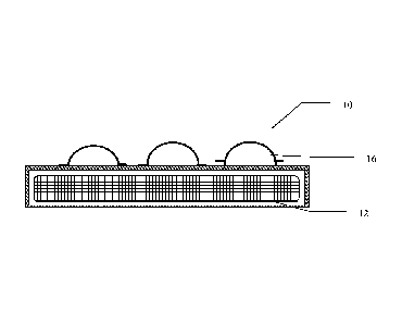
conductive or non-conductive material. Figure 2 illustrates an embodiment in
which the raised portions 16 are provided with apertures to enable the release
of one or more agents retained therein. The agents can be released either as a
result of heat generated by thermal reservoir 12 or by the removal of one or
CA 02715447 2010-08-12
WO 2009/108611
PCT/US2009/034945
12
more covering layers (not shown). In one embodiment, the interior surfaces
of the raised portions of the thermally conductive component are in direct
contact with the thermal fill material. In one embodiment, the thermally
conductive component is filled with metal pellets. In certain embodiments,
the side of the thermal reservoir which does not contain the thermally
conductive component (i.e. the opposite side) is layered with a rigid portion
or backing which allows the reservoir to maintain its shape upon placement
into the garment. In one embodiment the rigid portion or backing may be
constructed of a non-thermally conductive material such as but not limited to
1 o a plastic, polypropylene or polyethylene. In one embodiment the
rigid
portion or backing is layered on the side of a non-woven bag which contains
an exothermic heating composition.
Another aspect of the present invention relates to methods for treating
or managing pain, particularly muscle or joint pain, in humans. While heat,
and massage have long been recognized as effective modalities for managing
pain, the thermal insert of the present invention, in the embodiment wherein
the thermally conductive component has at least a portion of its surface
raised above the plane of the thermally active component, provides a means
for delivering heat, along with a massaging sensation to the user. Compared
to other methods of providing heat and massage, the method of the present
invention is advantageously portable, wearable, and long lasting, with
minimal effort required on the part of the user. An additional benefit of the
massaging action of the thermal insert of the present invention is the further
increase in blood flow to the affected area, facilitating the oxygenation, and
removal of waste from the affected tissue. Yet another benefit of the
massaging action of the thermal insert of the present invention is the sensory
cue to remind the user the product is working. Sensory cues can improve
patient compliance with a treatment regimen. One such regimen includes the
CA 02715447 2010-08-12
WO 2009/108611
PCT/US2009/034945
13
wearing of the thermal insert of the present invention in close contact with
the skin (either via a garment or patch) for from about 1 hour to about 16
hours. For example, a user can wear the thermal insert for from about 4 hours
to about 8 hours, or from about 8 hours to about 12 hours, or from about 8
hours to about 16 hours, providing heat to the affected muscles or joints
while simultaneously engaging in work or leisure activities.
In the therapeutic use of the thermal inserts of the present invention,
the thermally conductive component(s) are in contact with the body of the
user, either directly contacting the skin, or contacting the body through
1 o clothing or garments worn by the user. Simultaneously the
thermally
conductive component(s) are in contact with the thermal insert. The
thermally conductive component(s) serve to effectively transfer or re-
distribute heat or cold from the thermal inserts to the individual's body. In
addition, thermally conductive component(s) create a non-uniform thermal
sensations on the body or on the skin in case of direct application to skin,
whereby body or skin areas in immediate contact with the thermally
conductive component experience much stronger sensations of heat or cold
relative to the adjacent areas.
In one embodiment, the thermally conductive member is substantially
free of activated carbon, e.g. less than 0.1% by weight of the fill of the
thermally conductive component.
In one embodiment (not shown), the interior cavities created by
raised portions of the thermally conductive component are filled with
substances that are capable of retaining heat for extended periods of time,
such as thermal beads, encapsulated water, wax, phase change materials,
ceramics, sand, grains, rice, wheat, corn, etc. Even after the chemical
formulation inside the thermally active component stops delivering or
generating heat, the substances that are capable of retaining heat for
extended
CA 02715447 2010-08-12
WO 2009/108611
PCT/US2009/034945
14
periods of time inside the thermally conductive component can continue
releasing or absorbing heat for extended periods of time. Additionally, in
case of accidental overheating of the chemical formulation inside the
thermally active component, said substances are capable of absorbing the
excess heat thus providing protection form overheating.
Advantageously and beneficially, the space around the raised portions
of the thermally conductive component is available for removal and
evaporation of sweat and provides for areas of the body or skin not in contact
or not covered by any implement. Additionally, the thermal contrast
1 o (temperature difference between the skin and device) delivered to
the body
can be much higher when a thermally conductive component transferring
heat and transferring cold is immediately adjacent to the body. This contrast
can be achieved without significant losses of thermal energy due to heat
transfer. In one embodiment, the thermal reservoir is a thermal pack.
The number of the thermally conductive component(s) per single
thermal pack can vary from one to several. In one embodiment, from 6 to 30
or more thermally conductive components are installed on one bed or
thermal pack. Figure 1B exemplifies a device 10 having twelve conductive
components 16. In one embodiment the dimensions of the thermally
conductive components have a width from about 5 millimeters to about 50
millimeters, e.g. from about 7 millimeters to about 20 millimeters. In one
embodiment, the dimensions of the thermally conductive components have a
height from about 5 millimeters to about 50 millimeters, e.g. from about 7
millimeters to about 20 millimeters. As best illustrated in Figure 1A, height
is measured from the surface of device 10 to the apex of the thermal
conductive component 16.
In embodiments wherein the shape of the thermally conductive
components are semi-spherical, the diameter, which is equal to the width of
CA 02715447 2010-08-12
WO 2009/108611
PCT/US2009/034945
the component, is from about 5 millimeters to about 50 millimeters, e.g. from
about 10 millimeters to about 30 millimeters. In this embodiment the radius
of the semi-spherical component, which is equal to the height, is from about
2.5 millimeters to about 25 millimeters, e.g. from about 5 millimeters to
5 about 20 millimeters. Circular thermal conductive components 16
are shown
in Figure 1B.
In embodiments wherein the shape of the thermally conductive
components are elliptical, the diameter, which is equal to the maximum
width of the component, is from about 5 millimeters to about 50 millimeters,
10 e.g. from about 10 millimeters to about 30 millimeters. In this
embodiment
the height of the elliptical component, is from about 2.5 millimeters to about
millimeters, e.g. from about 5 millimeters to about 20 millimeters.
In certain embodiments, the thermally conductive components can be
defined by the volume of the internal space of the component. In certain
15 embodiments, the internal volume of a thermally conductive
component can
be from about 0.01 milliliters to about 50.00 millimeters, e.g. from about
0.03 milliliters to about 33.00 milliliters, e.g. from about 0.10 milliliters
to
about 2.00 milliliters.
In one embodiment, wherein more than one thermally conductive
20 components is present in the device, all thermally conductive
components
have the same height, while in another embodiment, some thermally
conductive components are higher and some are lower, for example a first
portion of the thermally conductive components are about 5 millimeters to
about 10 millimeters high, while a second portion are about 10 millimeters to
25 about 15 millimeters high, while an optional third portion are
about 15
millimeters to about 20 millimeters high.
CA 02715447 2010-08-12
WO 2009/108611
PCT/US2009/034945
16
The thermal device can be of any shape and size suitable for wearing
next to the skin of a human, and can be produced commercially in any shape
and size that can be die cut. For example, thermal insert 10 can be round,
triangular, square rectangular, pentagonal, hexagonal, etc. In one
embodiment, at least one dimension of the thermal insert is from about 1
inch to about 30 inches. In one particular embodiment, thermal reservoir 12
has a triangular shape with a width from about 2 to about 6 inches, and
overall length from about 2 to about 12 inches.
In certain embodiments, the thermal device can be substantially flat
with the thickness of the device ranging from about 2 millimeters to about 30
millimeters, and the other dimensions of the insert ranging from about 24
millimeters to about 720 millimeters.