Note : Les descriptions sont présentées dans la langue officielle dans laquelle elles ont été soumises.
CA 02716735 2016-01-14
61316-1121 =
- 1 -
INDUCTIVELY COUPLED SHELVING AND STORAGE CONTAINERS
BACKGROUND OF THE INVENTION
=
One of the problems associated with many of the electronics so common in
today's world is the necessity for the cords and cables associated with the
various electronic
devices.. Rechargeable cordless devices are a common alternative. These
devices still require
charging and the associated cords and cables to accommodate this charging.
Technology has been developed to address these limitations by providing an
inductively coupled power circuit. This circuit dynamically seeks resonance
and optimi7es
power transfer from a primary coil to a secondary device with a secondary
coil. This power
transfer can occur under multiple, varying load conditions. By using this
circuit, the primary
supply circuit adapts its operation to match the needs of the secondary
devices being supplied
with power. The circuit also allows the primary supply circuit to supply power
to multiple
secondary devices simultaneously.
SUMMARY OF THE INVENTION
Intelligent, inductively coupled power circuits have been developed to
transfer
power from a source to a device without the need for a wired connection.
Primary coils
inductively couple power to secondary coils integrated into devices such as
laptop computers,
PDAs, cell phones, and power tools. Embodiments of the present invention
incorporate this
inductive coupling technology into shelving units, storage containers, and
systems for
charging and storing devices.
=
CA 02716735 2016-01-14
61316-1121
- la-
According to one aspect of the present invention, there is provided an
inductively coupled shelving unit, comprising: a shelving unit having a shelf;
a first primary
coil integrated into the shelf and connected to a power source, the first
primary coil being
capable of inductively coupling power to a device containing a secondary coil;
one or more
indicators on a surface of the shelf that show a charging area for the first
primary coil, the
charging area being an area within which inductive coupling between the first
primary coil
and a secondary coil can be achieved; an inductively coupled storage container
including a
first secondary coil associated with an exterior surface of the container to
provide proximity
and alignment with the first primary coil when the container is placed on the
shelf, a first
compartment removeably retaining therein a first device having a second
secondary coil, the
first compartment including a second primary coil associated therewith and
positioned for
alignment with the second secondary coil, a second compartment removeably
retaining
therein a second device having a third secondary coil, the second compartment
including a
third primary coil associated therewith and positioned for alignment with the
third secondary
coil, and a distribution circuit that electrically couples between the first
secondary coil and the
second and third primary coils; and a docking unit that is coupled to the
shelf over the
charging area and that accepts the storage container, the storage container
being removeably
disposed in the docking unit and the docking unit retaining the storage
container against
lateral movement of the storage container in a plane parallel to the shelf.
According to another aspect of the present invention, there is provided an
inductively coupled storage container, comprising: a docking unit coupled to a
shelf; and a
storage container removably retained in the docking unit and including a first
secondary coil
associated with an exterior surface of the container in proximity and
alignment with a primary
coil that is associated with the docking unit or the shelf, a first
compartment configured to
receive and removeably retain therein a first electrical device having a
battery that includes a
second secondary coil, the first compartment including a first primary coil
associated
therewith and positioned for alignment with the second secondary coil when the
first electrical
device is disposed in the first compartment, a second compartment configured
to receive and
removeably retain therein a a spare battery having a third secondary coil and
being configured
CA 02716735 2016-01-14
61316-1121
- I b -
for use with the first electrical device, the second compartment including a
second primary
coil associated therewith and positioned for alignment with the third
secondary coil when the
spare battery is disposed in the second compartment, and a distribution
circuit that electrically
couples between the first secondary coil and the first and second primary
coils, the
distribution circuit adapting the second and third primary coils to the power
needs of the
battery and the spare battery, respectively.
According to yet another aspect of the present invention, there is provided a
system for storing and inductively charging devices, comprising: a surface; a
docking unit
coupled to the surface; a first primary coil integrated into the docking unit,
the first primary
coil being connected to a power source, and the first primary coil being
capable of inductively
coupling power to a first secondary coil; a storage container storing a
plurality of devices each
device including a battery associated with a second secondary coil, the first
secondary coil
being integrated into an exterior portion of the storage container and
receiving power
inductively coupled from the first primary coil integrated into the docking
unit, and the
docking unit removeably retaining the storage container; a plurality of second
primary coils
integrated into interior compartments of the storage container and being
capable of .
inductively coupling power received by the first secondary coil to the
plurality of devices; and
a distribution circuit disposed within the storage container that electrically
couples the first
secondary coil to the plurality of second primary coils.
In one embodiment, primary coils are integrated into shelves of a shelving
unit.
Primary coils of low, medium, and high power can be integrated into the
shelves in any
position, number, and combination. The shelving unit may be installed in a
vehicle.
In another embodiment, primary coils are integrated into a storage container.
Primary coils of low, medium, and high power can be integrated into the
storage container in
any position, number, and combination. The storage container may be a toolbox
configured to
receive and hold devices containing secondary coils. The storage container may
also
CA 02716735 2010-08-23
WO 2009/108959
PCT/US2009/041513
- 2 -
contain an integrated secondary coil configured to receive power inductively
coupled from an
external primary coil.
In yet another embodiment, a system of storing and charging tools is provided.
A shelving unit with primary coils integrated into the shelves is configured
to receive an
inductively coupled storage container. The storage container contains an
integrated
secondary coil configured to receive power inductively coupled from a primary
coil
integrated into the shelves. The power inductively coupled to the storage
container is then
again inductively coupled from primary coils integrated into the storage
container to
secondary coils in devices. The system may be installed in a vehicle.
This Summary is provided to introduce a selection of concepts in a simplified
form that are further described below in the Detailed Description. This
Summary is not
intended to identify key features or essential features of the claimed subject
matter, nor is it
intended to be used to limit the scope of the claimed subject matter.
BRIEF DESCRIPTION OF THE DRAWING
The present invention is described in detail below with reference to the
attached drawing figures, wherein:
FIG. 1 is a partial perspective view of an inductively coupled shelving unit;
FIG. 2 is a perspective view of an inductively coupled storage container;
FIG. 3 is a bottom orthogonal view of the inductively coupled storage
container of FIG. 2 with the bottom outer casing removed;
FIG. 4 is a partial perspective view of the inductively coupled storage
container of FIG.2;
FIG. 5 is a perspective view of an inductively coupled tool holster; and
FIG. 6 is an exploded perspective view of the inductively coupled tool holster
of FIG. 5.
DETAILED DESCRIPTION OF THE INVENTION
Embodiments of the present invention are described with specificity herein to
meet statutory requirements. However, the description itself is not intended
to limit the scope
CA 02716735 2016-01-14
61316-1121
=
- 3
of this patent. Rather, the inventor has contemplated that the claimed subject
matter might
also be embodied in other ways.
As noted in the background section, technology has been developed that
provides an intelligent, inductively coupled power circuit. This circuit
dynamically seeks
resonance and optimizes power transfer from a primary coil to a secondary
device with a
secondary coil. The circuit allows the primary coil to determine and provide
the power needs
of the secondary device. By using this circuit, the primary supply circuit
adapts its operation
to match the needs of the secondary devices being supplied with power. The
circuit also
allows the primary supply circuit to supply power to multiple secondary
devices
simultaneously. Examples of the circuit and the operation of the circuit are
contained in the
following U.S. Patents; 6,436,299; 6,673,250; 6,731,071; 6,806,649; 6,812,645;
6,831,417;
6,917,163; 6,975,198; 7,116,200; 7,118,240; 7,126,450; and 7,132,918.
The primary coils necessary to form an inductively coupled power circuit as
described above may be integrated in shelving units. Shelving units with
integrated primary
coils may be traditional shelving units in a room or office or the shelving
units may be
installed in a vehicle.
FIG. 1 shows a section of a shelving unit. Shelving unit 10 contains shelves
12, 14, 16, and 18. Although four shelves are shown in FIG. 1, an inductively
coupled
shelving unit could contain any number of shelves. Docking area 26 is attached
to shelf 16
and equipped with a primary coil. The primary coil could be attached to the
surface of
docking area 26, attached underneath docking area 26, or embedded within
docking area 26.
The primary coil could alternatively be integrated into shelf 16 rather than
docking area 26.
In one such embodiment, a cylindrical hole is bored in the shelf, and a
primary coil is
attached from underneath the shelf such that the top of the primary coil is
flush with the shelf
surface. A primary coil may also be installed beneath a shelf, attached by
screws, bolts, a
support bracket, or any other means. In other embodiments, a primary coil
could be
embedded in a shelf, with a power cord either leading from the edge of the
shelf or run
through hardware supporting the shelving unit.
With continued reference to FIG. 1, if shelving unit 10 is installed in a
vehicle,
the primary coil integrated into docking area 26 may draw, power from the
battery or
electrical circuitry of the vehicle. A shelving unit in a building may power
the integrated
primary coil through a connection to an electrical outlet. Docking area 26 is
formed to
CA 02716735 2010-08-23
WO 2009/108959
PCT/US2009/041513
- 4 -
provide a friction fit with tool case 28. Although a tool case is shown in
FIG. 1, the shelving
unit could be configured to receive and hold any inductively coupled storage
container.
Clasps, locking mechanisms, or other means for securing tool case 28 with
docking area 26
are also contemplated. The fit allows tool case 28 to be removed from docking
area 26 for
use, while maintaining the case 28 in place during storage. For implementation
in a vehicle,
the friction fit described above ensures that case 28 remains in place during
transit.
An inductively coupled storage container could also simply rest on an
inductively coupled shelving unit without docking surface 26. In such an
embodiment, a
primary coil would be integrated into shelf 16. A primary coil could also be
integrated into
shelf 16 rather than docking surface 26 even when docking surface 26 is used.
In other
embodiments, multiple primary coils are embedded or otherwise integrated into
shelf 16 or
docking surface 26. In embodiments with multiple primary coils, the multiple
primary coils
may be controlled by a single control circuit.
With continuing reference to FIG. 1, docking area 26 includes a small
indicator light 30 that illuminates when the case 28 is properly in place and
is charging. Case
28 preferably houses a line of cordless power tools. The power tools are
equipped with either
a common secondary coil and battery pack unit, or are all equipped with
individual batteries
and secondary coil units. Other devices containing secondary coils, such as
portable
computers and other portable electronic devices, could also be stored in an
inductively
coupled storage container that fits with docking area 26. Case 28 is
configured to distribute
power inductively coupled from the primary coil within docking area 26 to the
various
secondary coils within case 28. More specifically and as further described
below, the
primary coil in docking area 26 distributes power to a secondary coil
integrated into case 28.
The secondary coil integrated into case 28 distributes power to a number of
primary coils
integrated into the case. These integrated primary coils then inductively
couple power to the
secondary coils in the battery pack units. This embodiment allows the tools to
charge when
not in use. For shelving installed in a vehicle, tools would be able to charge
while a service
vehicle travels from job site to job site, allowing a worker to arrive at any
job site with
charged tools. In another embodiment, the primary coil in docking area 26
could inductively
couple power directly to a secondary coil contained in a battery pack unit of
a device.
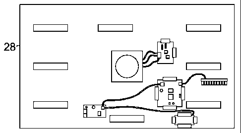
A detailed view of case 28 is shown in FIGS. 2-4. As shown in FIGS. 2 and 4,
case 28 is designed to house one or more power tools 32. The power tools are
cordless and
have associated battery packs 34. Case 28 is designed to orient the power
tools and hold
CA 02716735 2010-08-23
WO 2009/108959
PCT/US2009/041513
- 5 -
them in place. More specifically, case 28 has formed docking areas in the
bottom of the case
for each of a number of tools. These docking areas are designed to orient
battery pack 34 of
the tool directly over a primary coil in case 28. FIG. 2 shows case 28 without
tools.
FIG. 3 shows the interior of the bottom of case 28, which is provided with a
number of circuits and primary coils. As stated above, the primary coils are
oriented to
deliver power to the battery packs of the tools. The primary coils integrated
into case 28
receive power from the secondary coil integrated into case 28, which receives
power
inductively coupled from the primary coil integrated into docking area 26. The
primary coils
integrated into case 28 may be controlled by individual circuits or by a
single circuit control
mechanism. In embodiments with a plurality of primary coils, a single circuit
may control all
of the plurality of primary coils.
FIG. 5 and 6 illustrate an exemplary embodiment in which the inductively
coupled storage container is a tool holster 500. Holster body 502 contains
molded
compartment 504 configured to receive and hold cordless drill 506. Cordless
drill 506 can
easily be removed for use and charges when stored in tool holster 500. Molded
compartment
504 is best seen in FIG. 6. In other embodiments, holster body 502 could
contain one or
more molded compartments for receiving and holding other devices containing
secondary
coils. A primary coil is embedded or otherwise installed in holster body 502
in close
proximity to each molded compartment such that power is inductively coupled
from each
primary coil to each secondary coil in a device. In FIG. 5, a primary coil is
embedded or
otherwise installed in holster body 502 such that when cordless drill 506 is
placed in molded
compartment 504, the secondary coil in cordless drill 506 is in close
proximity with the
primary coil in holster body 502, and power is inductively coupled from the
primary coil to
the secondary coil.
With continued reference to FIG. 5 and 6, in some embodiments, holster body
502 also contains molded compartment 508 that is configured to receive and
hold extra
battery 510, which contains a secondary coil. A primary coil is embedded or
otherwise
installed in holster body 502 in close proximity to molded compartment 508
such that extra
battery 510 charges while stored in molded compartment 508. Still further
embodiments
include multiple primary coils able to charge multiple devices containing
secondary coils.
With continued reference to FIG. 5 and 6, holster body 502 is tapered such
that it is wider on top than on bottom. One side of holster body 502 is
substantially flat.
With reference now to FIG. 6, side panel 512 comprises the substantially flat
side. Tool
CA 02716735 2016-01-14
61316-1121
- 6 -
holster 500 can be installed against a side surface, such as a vehicle wall or
building wall.
When installed against a side surface, side panel 512 is screwed, bolted,
mounted in a
bracket, or otherwise installed against the side surface. If tool holster 500
is installed in a
vehicle, the embedded primary coils receive power from the vehicle's battery
or engine. If
tool holster is installed on a building wall, the primary coils may receive
power from an
electrical outlet or battery.
Primary coils may be low, medium, or high power. Low power primary coils
provide up to about approximately 20 watts of power. Medium power primary
coils provide
between about approximately 20 and 100 watts of power. High power primary
coils provide
greater than about approximately 100 watts of power. Any number and
combination of
primary coils may be integrated into docking area 26 and shelves 12, 14, 16,
and 18 of FIG.
1.
Returning to FIG. 1, for embodiments in which a primary coil in integrated
directly into shelves 12, 14, 16, or 18, and no docking surface is used,
indicators are
preferably used to facilitate proper placement of inductively coupled storage
containers.
Specifically, an outline of the area, along with logos, pictures or other
indicia, is preferably
provided on shelves 12, 14, 16, or 18. An indicator light may be present for
each primary
coil integrated into shelves 12, 14, 16, or 18. More specifically, an
indicator light is
embedded below the shelf surface and covered with a material that allows the
light to pass
through, such as Plexiglas. The indicator lights may turn on when a device is
placed over a
respective primary coil and is charging. Other indicators, such as dark lines,
may outline
charging areas for each primary coil. Outlining of charging areas may also be
done with
LEDs or other illuminated indicators.
In embodiments described herein with a plurality of primary coils, a single
=
circuit may control all of the plurality of primary coils.
The present invention has been described in relation to particular
embodiments, which are intended in all respects to be illustrative rather -
than restrictive.
Alternative embodiments will become apparent to those of ordinary skill in the
art to which
the present invention pertains without departing from its scope.
CA 02716735 2016-01-14
61316-1121
- 7 -
The scope of the claims should not be limited by the preferred embodiments set
forth in the examples, but should be given the broadest interpretation
consistent with the
description as a whole.