Note : Les descriptions sont présentées dans la langue officielle dans laquelle elles ont été soumises.
CA 02717611 2010-10-15
SURGICAL HEAD CLAMP
Field of Invention
[00011 The invention relates generally to apparatus and devices for
stereotactic surgery,
computer aided surgery and other similar medical procedures. More
particularly, a clamping
device for firm attachment to a head and for firmly and precisely positioning
and orienting
medical instruments attached to the clamping device is disclosed.
Background of Invention
[00021 During stereotactic surgery, intracranial operations, computer aided
tomography
imaging, or similar medical procedures, it is generally desirable to precisely
position and orient
various instruments relative to a patient's skull or other anatomy and to hold
the patient's head
or other anatomy immobilized relative to a support surface, such as an
operating table, an
operating chair or such other patient support structures.
[00031 For example, U.S. Pat. No. 6,117,143 describes an apparatus comprising
a head
clamp that includes three fixation pins to firmly secure the clamp to a
patient's skull, a
connector to firmly secure the clamp to a surgical table or like structures,
and an articulated
arm, including clampable joints, secured to the clamp for attachment of
medical or imaging
devices.
[00041 It is desirable that various parts of a head clamp, once a registration
to a
neuronavigation system has been completed, do not permit any movement relative
to each
other, so that registration may be maintained during the medical procedure,
such as stereotactic
surgery. It is also desirable that the head clamp permits its positioning
relative to a patient's
head differently to accommodate different procedures to be performed on the
patient and that
any interference with the performed procedure caused by any attached
accessories is
minimized.
[00051 The forgoing creates challenges and constraints for a clamping device
for firm
attachment to a head or other body parts and for firmly and precisely
positioning and orienting
medical instruments attached to the clamping device. There is therefore a need
for a clamping
21911540.4
CA 02717611 2010-10-15
-2-
device as compared to the existing art. It is an object of the present
invention to mitigate or
obviate at least one of the above mentioned disadvantages.
Summary of Invention
[0006] The present invention relates to a clamping device for firm attachment
to a patient's
body during medical procedures and for firmly and precisely positioning and
orienting
instruments attached to the clamping device. One aspect of the present
invention involves a
clamping device for firm attachment to a patient's head or other location of
the patient's body
during surgery or other medical procedures and for firmly and precisely
positioning and
orienting medical instruments attached to the clamping device. In one
embodiment, a clamping
device such as a head clamp may generally have a support member such as a
clamp arc, body
anchoring members such as fixation pins carried by the clamp arc, one or more
mounting
blocks for attachment of instruments, and securing arrangement to releasably
and
repositionably secure the one or more mounting blocks to the clamp arc.
[0007] In a first aspect of the invention, a clamping device is provided for
firm attachment
to a body part of a person. The clamping device includes a support member,
body anchoring
members carried by the support member, and a mounting block releasably secured
to the
support member. The support member is shaped to accommodate said body part and
includes a
plurality of connection sites, each connection site having opposed mounting
surfaces that are
converging toward a narrower side. The body anchoring members engage the body
part to
secure the support member on the body part such as head in outwardly spaced
position
therefrom. The mounting block has one or more connection surfaces for
attaching medical
instruments to the clamping device or for releasably securing said clamping
device to a support
surface. The mounting block has converging mounting surfaces complementary
with the
mounting surfaces of the support member for mating therewith, and securing
arrangement
releasably and repositionably securing the one or more mounting blocks to the
support member.
[0008] According to one feature of this aspect of the invention, the securing
arrangement of
the clamping device includes a connector, the connector securing the mounting
block to the
support member at least one of the plurality of connection sites by applying a
force urging
relative movement of the mounting block and the support member in a direction
for tighter
21911540.4
CA 02717611 2010-10-15
-3-
mating between the mounting surfaces of the mounting block and the mounting
surfaces of the
support member.
[0009] According to another feature of this aspect of the invention, at least
one of the body
anchoring members is a skull fixation pin, the skull fixation pin having a
threaded external
cylindrical body, and the support member has one or more threaded throughbores
to receive the
threaded external cylindrical body.
[0010] According to a further feature of this aspect of the invention, the
clamping device
further includes an accessory mounting block and an elevation block releasably
secured to the
accessory mounting block, the accessory mounting block having converging
mounting surfaces
to be mated with the outer converging surfaces of the support member.
[0011] In another aspect of the invention, a clamping device is provided for
firm
attachment to a head. The clamping device includes an arc-like support member,
a plurality of
skull anchoring members carried by said support member for engaging said head
to secure said
support member on said head in outwardly spaced position therefrom, and a
mounting block
releasably secured to the support member. The support member has a plurality
of threaded
throughbores and opposed outer surfaces that are converging toward a narrower
side formed at
each of the plurality of threaded throughbores. Each of the skull anchoring
members has an
external threaded cylindrical body sized to be threaded into said threaded
throughbores. The
mounting block has one or more mounting surfaces for attaching medical
instruments to the
clamping device or for releasably securing said clamping device to a support
surface. The
mounting block has inner surfaces to be mated with the outer surfaces of the
support member
and a thread bore. A shoulder bolt received in one of the threaded througbores
of the support
member and the threaded bore of the mounting block tightly secures the
mounting block to the
support member.
[0012] According to one feature of this aspect of the invention, the clamping
device also
has a removal tool, the removal tool having a handle portion, a front portion
sized to pass
through the threaded throughbores and a threaded body between the handle
portion and the
front portion, sized to be threaded into the threaded througbores of the
support member.
21911540.4
CA 02717611 2010-10-15
-4-
[0013] According to another feature of this aspect of the invention, the
clamping device has
a connection block releasably secured to the support member for securing said
clamping device
to a support surface, the connection block having converging mounting surfaces
to be mated
with the converging surfaces of the support member.
[0014] In other aspects the invention provides various combinations and
subsets of the
aspects described above.
Brief Description of Drawings
[0015] For the purposes of description, but not of limitation, the foregoing
and other
aspects of the invention are explained in greater detail with reference to the
accompanying
drawings, in which:
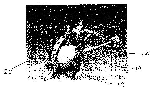
[0016] Figure 1 shows in a perspective view a clamping device, such as a head
clamp,
secured to a patient's head; also shown mounted to the head clamp is an
articulated, surgical
arm for carrying a medical device;
[0017] Figure 2 shows in another perspective view a head clamp with the
articulated arm
removed for better illustration;
[0018] Figure 3 shows in a cross-sectional view the connection between a
mounting block
and the head clamp arc;
[0019] Figure 4 shows a mounting block in a perspective view;
[0020] Figure 5 shows in a perspective view an accessory mounting block and an
elevation
block secured to the accessory mounting block;
[0021] Figure 6 shows in a perspective view an accessory mounting block;
[0022] Figure 7 shows in a perspective view an installation/removal tool for
installing and
removing a mounting block;
[0023] Figures 8A, 8B and 8C show in cross-sectional views alternative
configurations for
attaching a mounting block to a head clamp arc; and
[0024] Figure 9 shows in a perspective view a head clamp with a differently
constructed
accessory mounting block and an elevation post.
21911540.4
CA 02717611 2010-10-15
-5-
Detailed Description of Embodiments
[00251 The description which follows and the embodiments described therein are
provided
by way of illustration of an example, or examples, of particular embodiments
of the principles
of the present invention. These examples are provided for the purposes of
explanation, and not
limitation, of those principles and of the invention. In the description which
follows, like parts
are marked throughout the specification and the drawings with the same
respective reference
numerals.
[00261 In the description reference may be made to the general environment of
a clamping
device. By way of a general overview, Figure 1 shows in a perspective view a
clamping device
such as head clamp 20 firmly attached to a patient's head 10. Mounted to the
head clamp is an
articulated, surgical arm 12 for carrying a medical device, such as probe 14.
Figure 2 shows in
another perspective view a head clamp 20 like that shown in Figure 1, with the
articulated arm
12 removed for better illustration.
[00271 Head clamp 20 has a support member for carrying body anchoring members
and
mounting blocks. The support member is shaped to accommodate a patient's head
(or an
animal's head) or other parts of a patient's body (e.g., leg, arm or torso),
and may be arc-like.
Body anchoring members, such as fixation pins, fix the support member relative
the patient's
head, for example, and places the support member in spaced position outwardly
from the head.
Figures 1 and 2 illustrate an arc-like support member, namely a head clamp arc
22. Head
clamp arc 22 can have a generally circular shape. The circular shape allows
the arc to be
oriented in any suitable position to suit the needs of performed procedure.
Head clamp arc is
suitably sized to fit human and/or animal skull sizes. It will be appreciated,
however, that the
support member may also take other shapes, such as a ring, a plate having an
inner curved edge
etc., to accommodate a head, a leg, an arm, among others.
[00281 Head clamp arc 22 has a plurality of threaded throughbores, namely,
threaded
throughholes 24, spaced from each other along the arc and formed generally
along a radial
direction, to accept skull fixation pins 26. Each skull fixation pin 26 has an
externally threaded
cylindrical body 28 that can be threaded into one of the threaded throughholes
24 and a sharp
pin tip 30 mounted to the cylindrical body for engaging skull 10. Of course,
for engaging other
body parts, such as leg or torso, fixation pins may be replaced by fixation
pads as body
21911540.4
CA 02717611 2010-10-15
-6-
anchoring members, to reduce discomfort that might be caused by a pin but
still effectively
maintain the base support member in a fixed relationship to the engaged body
part.
[00291 Head clamp arc 22 has opposed outer surfaces 32, formed at connection
sites 34
surrounding each threaded throughholes (more clearly shown in Figure 3). As
can be seen
more clearly in Figure 3, a radial outward portion of head clamp arc 22 has a
cross-sectional
shape that is essentially trapezoidal in a radial plane, with outer surfaces
of the trapezoidal arc
converging radially outwardly. In other words, a portion of the outer surfaces
32, namely the
portion forming the trapezoidal shape, converge radially outwardly. It will be
understood,
however, that the cross section of the head clamp arc may not always be
trapezoidal. It may
take a different shape. In general, the cross section includes a portion of
converging outer
surfaces. While the trapezoidal shape shown in Figure 3 has outer surfaces
converging radially
outwardly, the converging surfaces may also converge inwardly. Further,
conveniently, the
outer surfaces may extend over the entire length of the arc, such as shown in
Figure 2.
[00301 Referring to Figures 2, 3 and 4, head clamp 20 includes one or more
mounting
blocks 36 for mounting to the head clamp arc 22 at connection sites 34.
Mounting block 36 has
opposing inner surfaces 38 to be mated with the outer surfaces of the head
clamp arc 22 at a
connection site. Inner mounting surfaces 38 have at least a converging portion
matching the
converging portion of the outer mounting surfaces 32. Figure 3 shows a
mounting block 36
that has a trapezoidal slot 40 matching the trapezoidal cross-sectional shape
42 of the head arc
clamp, with matching and complementary mounting surfaces. These matching
mounting
surfaces, i.e., the complementary, converging outer surfaces 32 of head clamp
arc 22 and inner
surfaces 38 of the trapezoidal slot 40 of mounting block 36 allow the mounting
block 36 to be
firmly attached to the head clamp arc 22, as will be further described now. As
can be seen in
Figure 3, both trapezoidal cross sections have narrower end located further
outwardly of the
center. This allows the mounting block to be located on the outside of the
head clamp arc 22.
A securing arrangement is provided to force the mounting block toward the head
clamp arc, or
more generally, to force the mounting block and the head clamp arc toward each
other, so that
the mounting block is releasably secured to the head clamp arc when needed. A
shoulder bolt
44, for example, may be used for pulling the mounting block toward the head
clamp arc. A
threaded hole 46 is formed in the mounting block 36. The shoulder bolt 44 is
sized smaller
21911540.4
CA 02717611 2010-10-15
-7
than the threaded throughhole 24 of the head clamp arc so it can pass through
the threaded
throughhole 24 unhindered and threaded into the threaded hole 46 of the
mounting block to pull
the mounting block toward the head clamp arc. The shoulder bolt 44 pulls the
mounting block
toward the head clamp arc 22 until the mounting block 36 cannot be pulled any
closer to the
head clamp arc 22 and will lock the mounting block onto the head clamp arc.
Any translational
movement of the mounting block 36 is restricted by the shoulder bolt 44 and
the matching
converging surfaces. Any rotational movement of the mounting block rotate
relative to the head
clamp arc is restricted by tight engagement of matching converging surfaces of
the mounting
block with those of head clamp arc. As will be understood and as will be
illustrated in some
examples to be provided later, a variety of methods may be employed to force
the mounting
block and the head clamp arc toward each other. Such securing arrangement also
is not limited
to mechanical configurations. For example, the mounting block or head clamp
arc 22 may be
magnetized (or selectively magnetized by electricity) for pulling the mounting
block toward the
head clamp arc.
[00311 Referring to Figures 2 and 4, mounting block 36 has one or more outer
connection
surfaces formed thereon for connection of medical instrument or accessories to
the head clamp.
Mounting block 36 may be a starburst connection block with toothed connection
surfaces 48
and a central hole as shown in Figure 4. The starburst connection block may be
used to mount
a variety of devices with mating toothed connection surfaces. A central hole
50 is formed near
the center of the toothed connection surfaces 48. The central hole 50 may be
threaded, in
which may be threaded a bolt or screw, or a throughhole for a bolt to pass
therethrough, to
securely attach a device to the starburst connection block. The cooperating
toothed connection
surfaces of the mounting block and the mounted devices also encourage
precisely locating the
connected device at one of the angular positions defined by the toothed
connection surfaces.
One such mating device or attachment may be an articulated surgical arm 12 to
be attached to
support instruments used in surgical procedures. Another such attachment may
be a marker for
providing a reference point during neurovavigation. The starburst connection
block also allow
mounting of other attachments, such as an attachment to hold the mounting
block in a fixed
position relative to an operating table, operating chair, desk or other
mounting support structure
or surface. This would hold a patient's head immobilized for surgery or other
procedures.
21911540.4
CA 02717611 2010-10-15
-8-
[0032] As noted, a surgeon may need to locate the head clamp 20 to different
positions
relative to the head or orient differently for different procedures while
minimizing interference
of the head clamp with the procedure performed. The medical instrument or
devices attached
to the head clamp may also need to be located differently relative to the head
clamp arc 22 as
required by different procedures. This can be accomplished by threading skull
fixation pins 26
into different threaded throughholes 24, or repositioning the mounting block
or blocks to
different connection sites, or connecting the instruments or devices to
different toothed
connection surfaces of the mounting block or blocks. To reposition a mounting
block 36, the
shoulder bolt 44 is removed to allow separation of the mounting block from the
header clamp
arc. A special tool, as will be fully described below, may be provided for
facilitating the
separation of the mounting block form the header clamp arc.
[0033] There may also be situations where a skull fixation pin 26 may still
interfere with
the procedure performed even when it is moved to a different threaded
throughhole 24. It is
therefore desirable that skull fixation pins may be secured to head clamp arc
22 at a location
generally spaced from the plan defined by head clamp arc. Similarly,
attachments secured to a
mounting block may interfere with performed procedures and moving attachments
to a location
spaced from the plan defined by head clamp arc may minimize the interference.
[0034] Figure 5 shows an accessory mounting block 52 and an elevation block 54
secured
to the accessory mounting block. As can be more clearly seen in Figure 6,
accessory mounting
block 52 has a front slot 56 that has front converging surfaces 58 for mating
with the outer
surfaces of head clamp arc 22. Several threaded throughbores 60 are provided
so that a
shoulder bolt 44 inserted from the inside radius of the head clamp arc 22 can
pass through a
throughhole 24 and thread into one of the threaded throughbores 60 to secure
the accessory
mounting block to head clamp arc. Accessory mounting block also has a rear
slot 62 that has
opposing, rear converging surfaces 64 for accepting elevation block 54.
[0035] Referring to Figure 5, elevation block 54 has an elongated body 66
sized to be
partially received in the rear slot and slidable along the rear slot 62. The
elongated body has
opposed outer converging surfaces 68 that converge toward its front side 70.
The outer
converging surfaces of the elevation block are to be mated with the rear
converging surfaces 64
of the accessory mounting block 52 when a section of the elongated body is
received in the rear
21911540.4
CA 02717611 2010-10-15
-9-
slot. After the elevation block is suitably positioned relative to the
accessory mounting block, a
shoulder bolt 44 is passed through a slot 72 formed in the elongated body 66,
threaded into one
of the threaded throughbores 60, and tightened to pull the elevation block
toward the accessory
mounting block until they cannot be moved closer toward each other. The
elevation block 54 is
thus locked in place and immovably secured to the accessory mounting block 52.
Moving the
elevation block to another location relative to the accessory mounting block
is done by
unscrewing the shoulder bolt securing the elevation block to the accessory
mounting block and
thereby allowing their separation and tightening the shoulder bolt again after
the elevation
block is appropriately repositioned.
(0036] Elevation block has a mounting site 74 formed integral with the
elongated body 66.
Mounting site 74 may be configured to accept a skull fixation pin, or for
connection of
attachment thereto. For example, a threaded throughhole 24 may be formed at
the mounting
site 74 for accepting a skull fixation pin. The threaded throughhole 24 may be
oriented
generally parallel to the plane defined by the head clamp arc 22 or angled
with respect to the
plane. The mounting site may also have one or more toothed connection surfaces
48 like that
of mounting block 36, formed on side surfaces at mounting site 74 or front
side 70, for
attaching medical instrument or connection of attachment.
(0037] Conveniently, a combined installation and removal tool 76 is provided
for easy
installation and removal of skull fixation pins. Figure 7 illustrates such a
combined installation
and removal tool 76, which has an elongated cylindrical body 78, which
includes a front
portion 80 and a threaded body portion 82, and a handle portion 84 for fixing
a handle 86
thereto. The threaded body portion 82 is sized to be threaded into a threaded
throughhole 24 of
the head clamp arc 22. The front portion 80 is sized to pass through the
threaded throughholes
24 unhindered. The front portion 80 does not need to be threaded and is sized
for pushing
starburst mounting block 36 away from the head clamp arc 22. For example, the
front portion
may be sized larger than the threaded hole 46 of the mounting block.
Alternatively, the front
portion may be sized smaller than the threaded hole 46 but sufficiently long
so that the front
portion (or its tip 88) can reach the bottom of the threaded hole 46. The tip
of the front portion
may have a non-cylindrical shape (such as a hex tip 88 or a tip of any other
suitable shape) that
fits into a complementarily shaped hole (such as a hex hole 90) formed on the
bolt head 92 of
21911540.4
CA 02717611 2010-10-15
-10-
the shoulder bolt 44, so that the installation and removal tool can also be
used for tightening or
loosening the shoulder bolt.
[0038] To removal a starburst mounting block or accessory mounting block, the
shoulder
bolt is first loosened and removed, using the combined installation and
removal tool 76, for
example. It will be appreciated that when a mounting block is tightened onto
the head clamp
arc, the converging surfaces tend to lock the mounting block onto the arc and
it may be difficult
to separate the starburst mounting block from the head clamp arc.
Conveniently, the installation
and removal tool can be threaded into the threaded throughhole until the front
portion 80 is in
contact with the bottom of the threaded hole 46 of the starburst mounting
block 36 and pushes
the starburst mounting block 36 off of the head clamp arc.
[0039] As will be appreciated, the converging nature of the converging
surfaces of the
mounting block and the head clamp arc assists the tight engagement of the
mounting block with
the head clamp arc and prevents their relative movement once the mounting
block is tightened
and locked in place. The converging angle, namely the angle a between the
converging
surfaces, is generally in the range of 5 to 40 degrees. Depending or materials
used and whether
the contacting surfaces of the mounting block and the clamp arc are formed
using the same
material, the converging angle may be outside this range. However, to obtain
satisfactory
results, the converging angle should not be significantly larger than 60
degrees or much smaller
than 2 degrees. As will also be appreciated, the converging angle may be
evenly or unevenly
divided between the pair of converging surfaces of the slot or arc. Figure 3
shows the
converging angle to be evenly divided, but that is not necessary. It is found
that a converging
angle of about 10 degrees, divided evenly between the pair of converging
surfaces, tends to
provide satisfactory results with mounting block and head clamp both made of
steel.
[0040] As noted earlier, there are different ways of configuring the
converging surfaces and
the engagement arrangement to tighten the mounting block, other than that is
shown in Figure
3. For example, Figure 8A is a cross-sectional view of a mounting block 36 and
a head clamp
arc 22 at a connection site 34 (see Figure 2) illustrating one such
alternative configuration. The
mounting block has a trapezoidal slot 40 that matches the trapezoidal cross-
sectional shape 42
of the head clamp arc. The converging surfaces 94 converge outwardly along a
radial
direction. Unlike that shown in Figure 3, the shoulder bolt passes through a
throughhole of the
21911540.4
CA 02717611 2010-10-15
-11-
mounting block and is threaded into the threaded hole of the head clamp arc.
Tightening the
shoulder bolt 44 pulls the head clamp arc 22 towards the mounting block 36 to
lock the
mounting block onto the head clamp arc. Figure 8B shows in a cross-sectional
view another
alternative configuration. The converging surfaces 94 converge inwardly along
a radial
direction. A shoulder bolt 44 is threaded into a threaded throughhole of the
head clamp arc 22
and pushes the mounting block 36 away from the head clamp arc to tightly lock
the mounting
block on the head clamp arc. Similarly, Figure 8C shows in a cross-sectional
view yet another
alternative configuration. The converging surfaces 94 converge inwardly along
a radial
direction, as in Figure 8B. The shoulder bolt 44 is threaded through a
threaded throughhole of
the mounting block 36 and pushes the head clamp arc 22 away from the mounting
block, in
order to lock the mounting block tightly onto the head clamp arc. These are
but a few
examples to illustrate different configurations of engagement arrangement, for
tightly locking
the mounting block onto the head clamp arc. The same configurations may be
applied to
accessory mounting blocks, too. Other configurations are also possible. For
example, it is not
necessary to use a threaded shoulder bolt. Magnetic force can be utilized to
force a mounting
block towards or away from a head clamp arc. Such magnetic force also can be
selectively
applied, for example, by utilizing electromagnet.
[0041] Figure 9 shows in a perspective view a head clamp 20' with a
differently
constructed accessory mounting block 52' and elevation block 54'. Unlike
accessory mounting
block 52 shown in Figure 6, which provides an open rear slot 62 for receiving
an elongated
body 66 of elevation block 54, the differently constructed accessory mounting
block has a
throughhole 96 defined therein. Elevation block 54 has the form of a post.
Elevation post 54'
is slidably received in throughhole 96. Elevation post 54' and its matching
throughhole may
have a cylindrical shape as shown in Figure 9 or any other suitable shape. A
skull fixation pin
26 is threaded in a threaded throughhole 24 provided on elevation post 54', to
carry the pin 26
with the elevation post 54' as the elevation post slides along the throughhole
96. A locking nut
98, such as a wing nut or a thumbnut, may be provided to releasably lock pin
26 relative to the
elevation post 54'. A locking thumbscrew 94, or any other suitable locking
screw, is provided
to releasably secure the elevation post relative to the accessory mounting
block 52'. To
minimize damages to the elevation block 52', the tip of the locking thumbscrew
may be made
from a plastic material.
21911540.4
CA 02717611 2010-10-15
-12-
[00421 Various embodiments of the invention have now been described in detail.
Those
skilled in the art will appreciate that numerous modifications, adaptations
and variations may be
made to the embodiments without departing from the scope of the invention.
Since changes in and
or additions to the above-described best mode may be made without departing
from the scope of
the invention, the invention is not to be limited to those details but only by
the appended claims.
21911540.4