Note : Les descriptions sont présentées dans la langue officielle dans laquelle elles ont été soumises.
CA 02717696 2010-09-03
WO 2009/109040 PCT/CA2009/000258
FILTER DEVICE AND METHOD
REFERENCE TO COPENDING APPLICATIONS
The entire subject matter of US Provisional application 61/064,429, filed
March 5, 2008 and entitled
FILTER DEVICE AND METHOD is incorporated herein by reference. The applicants
claim priority
benefit under Title 35, United States Code, Section 119 of the above
application.
BACKGROUND OF THE INVENTION
1. FIELD OF THE INVENTION
The present invention relates to filter units and methods of filtering.
2. DESCRIPTION OF THE RELATED ART
In filter units for industrial operations, it is a common practice to provide
a housing with an inlet for the
unfiltered liquid, an outlet for the filtered liquid and a filter layer
between the inlet and the outlet to retain
the contaminant in the liquid. Further, in some instances or applications,
there may be a need to provide a
means for supporting and/or retaining the filter layer during flow conditions.
A need exists for a filtering system that is efficient and effective.
Furthermore, it is desirable that the
filtering system at the same time, be constructed of such materials that it is
relatively inexpensive to
manufacture, and such that maintenance in operation is relatively low.
It is an object of the present invention to provide a novel approach to the
task of filtering.
IFM-FSF-PCT I
CA 02717696 2010-09-03
WO 2009/109040 PCT/CA2009/000258
SUMMARY OF THE GENERAL INVENTIVE CONCEPT
In one exemplary embodiment, there is provided a filter unit assembly and a
method for filtering flowable
media comprising a filter housing for a tubular filter having an outer
filtering surface and an inner filtering
surface. The filter housing comprises a filter support having a first
permeable support portion adapted to
support the outer filtering surface, and a second permeable support portion
adapted to support the inner
filtering surface. The second permeable support portion is substantially
concentric to, bounded by and
spaced apart from the first permeable support portion and is characterized in
that the second permeable
support portion is configured such that the surface area of the first
permeable support portion and the area
second permeable support portion are substantially equal.
In an exemplary embodiment, there is provided a filter assembly comprising a
housing having a first open
end, a first closed end, an inlet, and an outlet; a filter support, the filter
support has a first permeable
support portion and a second permeable support portion nested within the first
permeable support portion,
the filter support is seated within the housing between the inlet and the
outlet; a filter element having a
second open end and a second closed end, the filter element is reversed upon
itself and positioned between
the first and second permeable support portions to form concentrically
disposed inner and outer filtering
surfaces, the first and second permeable support portions has substantially
equal surface area.
In some exemplary embodiments, the filter element has substantially constant
lateral dimensions between
the second open end and the second closed end.
In some exemplary embodiments, the filter element is cylindrical in shape
between the second open end
and the second closed end.
In some exemplary embodiments, the filter element is formed from one or more
blanks of filter material.
IFM-FSF-PCT 2
CA 02717696 2010-09-03
WO 2009/109040 PCT/CA2009/000258
In some exemplary embodiments, the housing includes an elongate body portion
with a cover portion to
close the first open end.
In some exemplary embodiments, the outlet is associated with the first closed
end and the inlet is associated
with the cover portion.
Some exemplary embodiments, further comprise a fluid boundary member located
within the housing and
oriented to define a pair of fluid regions in the housing, the filter support
is seated at the fluid boundary
member.
In some exemplary embodiments, the fluid boundary member includes a plate
portion with a first peripheral
region, a passage formed therein and arranged adjacent the first peripheral
region, the passage bordered by
a corresponding second peripheral region, the filter support extends through a
corresponding passage and
engages the fluid boundary member at the second peripheral region.
In some exemplary embodiments, the filter support is removable.
In some exemplary embodiments, wherein the filter support is a basket.
In some exemplary embodiments, the filter support further comprising a lip
that seats on the fluid boundary
member.
In some exemplary embodiments, wherein the fluid boundary member has a recess
to receive the lip.
In some exemplary embodiments, the first and/or second permeable support
portion being perforated,
woven, molded, punched or stretched.
IFM-FSF-PCT 3
CA 02717696 2010-09-03
WO 2009/109040 PCT/CA2009/000258
In some exemplary embodiments, the filter support has an intermediate region,
the first permeable support
portion is affixed to the second permeable support portion at the intermediate
region.
In some exemplary embodiments, the second permeable support portion has an
open end through the
intermediate region.
In some exemplary embodiments, the second permeable support portion has a
closed or permeable end wall
through the intermediate region.
In some exemplary embodiments, the first and second permeable support portions
are integrally formed.
In some exemplary embodiments, the second permeable support portion is
removably mounted within the
first permeable support portion.
In some exemplary embodiments, the first and second permeable support portions
are perforated by
stamping, metal expanding, wire forming or plastic molding.
In some exemplary embodiments, the second permeable support portion has a
regular or irregular
undulating periphery in cross section.
In some exemplary embodiments, the second permeable support portion has an
irregular or regular
undulating periphery in cross section to form a plurality of lobes.
In some exemplary embodiments, the second permeable support portion includes a
corrugated support
surface.
In some exemplary embodiments, the filter housing has an elongate first
central axis, the first and second
permeable support portions is concentrically aligned with a second central
axis, the second central axis is
IFM-FSF-PCT 4
CA 02717696 2010-09-03
WO 2009/109040 PCT/CA2009/000258
substantially aligned with the first central axis, the second permeable
support portion has a plurality of
corrugations, each corrugation forming a lobe with a third axis, each third
axis is substantially parallel with
the second central axis.
In some exemplary embodiments, the filter element has a sealing member that
mates with the fluid
boundary member.
In some exemplary embodiments,. the filter support has a lip, the filter
element having a sealing member
that mates with the fluid boundary member and/or the lip.
In some exemplary embodiments, the filter support has a lip, the filter
element having a sealing member
that mates with the fluid boundary member and/or the lip of the filter support
and/or the cover portion.
In some exemplary embodiments, the filter element has one or more raised,
flush, movable and/or integral
handles.
In some exemplary embodiments, the first permeable support portion has a third
open end and a seating
portion adjacent the third open end to sealingly engage the second open end of
the filter element.
In some exemplary embodiments, the first permeable support portion has a
distal end region located
adjacent the intermediate region, the second permeable support portion has a
third closed end, the filter
element is dimensioned so that the second closed end of the filter element is
positioned adjacent the third
closed end.
In some exemplary embodiments, the filter support includes an annular bridging
portion joining the first
and second permeable support portions at the intermediate region.
IFM-FSF-PCT 5
CA 02717696 2010-09-03
WO 2009/109040 PCT/CA2009/000258
In some exemplary embodiments, the second permeable support portion includes
an end wall portion at the
third closed end.
In some exemplary embodiments, one or both of the annular bridging portion and
the end wall are
permeable.
Some exemplary embodiments, further comprise a cap portion removably
positioned on or fixed to the third
closed end.
In some exemplary embodiments, the cap portion is permeable.
Some exemplary embodiments, further comprise one or more fixed or removable
bracing portions for
bracing the first support portion, the second support portion, and/or the
intermediate portion against
operating pressures within the housing.
In some exemplary embodiments, the bracing portions are provided by one or
more annular elements
placed at regular or irregular intervals along the inner periphery of the
second support portion.
In some exemplary embodiments, the annular elements include rings.
In some exemplary embodiments, the filter element has a peripheral filter ring
to engage the filter support,
the filter support includes a first interruptive formation to be positioned
adjacent the filter ring, the filter
ring includes a second formation to be positioned adjacent and/or engage the
first formation in a
complementary fashion, the first and second formations is arranged to engage
when the filter ring and filter
support are in an operative fluid sealing orientation to form an effective
fluid seal therebetween.
IFM-FSF-PCT 6
CA 02717696 2010-09-03
WO 2009/109040 PCT/CA2009/000258
In some exemplary embodiments, the first and/or second formations are arranged
so that the presence of
one without the other in an operative fluid sealing orientation between the
filter and filter support
operationally inhibits the effective fluid seal.
In another alternative exemplary embodiment, there is provided a filter
assembly comprising a housing that
has a first open end, a first closed end, an inlet, and an outlet; a plurality
of filter supports, each filter
support has a first permeable support portion and a second permeable support
portion nested within the first
permeable support portion, each filter support is seated within the filter
housing between the inlet and the
outlet; a plurality of filter elements, each received in a corresponding
filter support, each filter element has
a second open end and a second closed end, each filter element is reversed
upon itself and positioned
between the corresponding first and second permeable support portions to form
concentrically disposed
inner and outer filtering surfaces, the second permeable support portion has a
surface area of about equal to
a surface area of the first permeable portion.
In some exemplary embodiments, each filter element has substantially constant
lateral dimensions between
the second open end and the second closed end.
In some exemplary embodiments, each of the filter elements is cylindrical in
shape between the second
open end and the second closed end.
In some exemplary embodiments, the filter housing includes an elongate body
portion with a cover portion
to close the open end, the outlet is associated with the first closed end and
the inlet is associated with the
cover portion.
Some exemplary embodiments further comprise a fluid boundary member located
within the housing and
oriented to define a pair of fluid regions in the housing, each filter support
is seated at the fluid boundary
member.
IFM-FSF-PCT 7
CA 02717696 2010-09-03
WO 2009/109040 PCT/CA2009/000258
In some exemplary embodiments, the fluid boundary member includes a plate
portion with a first peripheral
region, a plurality of passages formed therein and arranged along the
peripheral region, each passage
bordered by a corresponding second peripheral region, each filter support
extending through a
corresponding passage and engaging the fluid boundary member at the
corresponding second peripheral
region.
In yet another exemplary embodiment, there is provided a retainer basket for
use in a liquid filtration
assembly comprising an outer permeable support portion and an inner permeable
support portion, the outer
permeable support portion has an outer diameter sufficient to allow the
retainer basket to seat within a
pressure vessel, the outer permeable support has a first operative portion of
a first length dimension, the
inner permeable support has a second operative portion of a second length
dimension, the first and second
length dimension is substantially equal, the inner permeable support portion
has a surface area which is
substantially equal to a surface area of the outer permeable support portion.
In yet another exemplary embodiment, there is provided a retainer support for
use in a filtration assembly
comprising an outer permeable support portion and an inner permeable support
portion, the outer
permeable support portion having an outer diameter sufficient to allow the
retainer support to seat within a
pressure vessel, the inner permeable support portion having a surface area
which is substantially equal to a
surface area of the outer permeable support portion.
In some exemplary embodiments, the outer permeable support having a first
operative portion of a first
length dimension, the inner permeable support having a second operative
portion of a second length
dimension, the first and second length dimension being substantially equal.
In some exemplary embodiments, the inner support portion is removably attached
to the outer support
portion.
IFM-FSF-PCT 8
CA 02717696 2010-09-03
WO 2009/109040 PCT/CA2009/000258
In yet another alternative exemplary embodiment, there is provided a kit for
retrofitting a retainer basket for
use in a liquid filtration assembly, the retainer basket of the type having an
outer permeable support
portion, the kit comprising an inner permeable support portion removably
positionable in the outer
permeable support portion, the inner permeable support portion has an
effective fluid filtering surface area
which is substantially equal to an effective fluid filtering surface area of
the outer permeable support
portion.
In some exemplary embodiments, the inner permeable support portion removably
attachable to the outer
permeable support portion.
Some exemplary embodiments, further comprise a plurality of filter elements
for use in the retainer basket.
Some exemplary embodiments further comprise one or more fastener elements for
fastening the inner
permeable support portion and/or the filter elements to the outer permeable
support portion.
In another alternative exemplary embodiment, there is provided a filter
assembly kit for use with a liquid
filtration assembly comprising; a retainer basket, the retainer basket has a
first permeable support portion
and a second permeable support portion mounted within the first permeable
support portion, the filter
basket is operable to be seated within a liquid filtration vessel; a plurality
of filter elements, each filter
element has an open end and a closed end and has substantially constant
lateral dimensions between the
open end and the closed end, the filter element is operable to be reversed
upon itself to form a
concentrically disposed inner and outer filtering surfaces and to be installed
in the retainer basket in order
to be supported by the first and second permeable support portions, the second
permeable support portion
has a surface area which is substantially equal to the a surface area of a
first permeable support portion.
In still another alternative exemplary embodiment, there is provided a filter
assembly comprising; a
housing has an open end, a closed end, an inlet, an outlet, and a support
portion, the support portion has a
first permeable support portion and a second permeable support portion mounted
within the first permeable
IFM-FSF-PCT 9
CA 02717696 2010-09-03
WO 2009/109040 PCT/CA2009/000258
support portion, the support portion is seated within the housing, a
collapsible filter bag has a second open
end and a second closed end and reversed upon itself to form a concentrically
disposed inner and outer
filtering surfaces is supported by the first and second permeable support
portions, the second permeable
support portion has a footprint bounded by a theoretical circle of a
predetermined circumference, the
second permeable support portion has a plurality of irregular or regular
formations that provide the second
permeable support portion with an increased circumference beyond that of the
circumference of the
theoretical circle, so that the circumference of the second permeable support
portion is substantially equal
to the circumference of the first permeable support portion.
In still yet another alternative exemplary embodiment, there is provided a
filter assembly comprising; a
housing has an open end, a closed end, an inlet, an outlet, and a support
portion, the support portion has a
first permeable support portion and a second permeable support portion mounted
within the first permeable
support portion, the support portion is seated within the housing, a
collapsible filter bag has a second open
end and a second closed end and reversed upon itself to form a concentrically
disposed inner and outer
filtering surfaces being supported by the first and second permeable support
portions, the second permeable
support portion has a footprint bounded by a theoretical circle of a
predetermined circumference, the
second permeable support portion has a plurality of irregular or regular
formations that provide the second
permeable support portion with an increased surface area per unit length,
beyond that of the surface area of
the theoretical circle per unit length , so that the surface area per unit
length of the second permeable
support portion is substantially equal to the surface area per unit length of
the first permeable support
portion.
In another alternative exemplary embodiment, there is provided a filter
assembly comprising a housing has
an open end, a closed end, an inlet, an outlet, and a support portion, the
support portion has a first
permeable support portion and a second permeable support portion mounted
within the first permeable
support portion and is seated within the housing, a cylindrical collapsible
filter bag has a body with a
second open end and a second closed end, the body has a substantially constant
diameter between the
second open end and the second closed end, the body is reversed upon itself to
form a concentrically
IFM-FSF-PCT 10
CA 02717696 2010-09-03
WO 2009/109040 PCT/CA2009/000258
disposed inner and outer filtering surfaces to be supported in an operative
position by the first and second
permeable support portions, the first permeable support portion is cylindrical
and has a first inner surface
with a first circumference which is configured not to exceed the circumference
of the filter bag, the second
permeable support portion has a plurality of regular or irregular elongate
projections distributed laterally
therealong to provide a second circumference that is at most equal to the
circumference of the filter
element, the filter element has a first cylindrical portion so that, under
predefined operating conditions,
substantially all of the first cylindrical portion that is aligned with the
first support is directly supported by
the first support portion and a second cylindrical portion so that, under
predefined operating conditions,
substantially all of the second cylindrical portion that is aligned with the
second support portion is directly
supported by the second support portion.
In some exemplary embodiments, the filter support has an intermediate region,
the first permeable support
portion is affixed to the second permeable support portion at the intermediate
region, the filter element
includes a bridging portion between the first and second cylindrical portions,
so that, under predefined
operating conditions, the bridging portion is directly supported by the
intermediate portion.
In some exemplary embodiments, the second permeable support portion is
corrugated.
Some exemplary embodiments further comprise a cap portion removably positioned
or fixed at the third
closed end.
In some exemplary embodiments, the cap portion includes a plurality of ridges
extending radially there
along, each to align with a corresponding formation.
In some exemplary embodiments, the cap portion is permeable.
In yet another alternative' exemplary embodiment, there is provided a filter
assembly comprising a housing
that has an open end, a closed end, an inlet, an outlet, and a support
portion, the support portion has a first
IFM-FSF-PCT 1 1
CA 02717696 2010-09-03
WO 2009/109040 PCT/CA2009/000258
permeable support portion and a second permeable support portion mounted
within the first permeable
portion and is seated within the housing, a filter element has a second open
end and a second closed end
reversed upon itself to form a concentrically disposed inner and outer
filtering surfaces that is supported by
the first and second permeable support portions, the filter element further
has a sealing structure on the
second open end to mate with the support portion, the second permeable support
portion has plurality of
lobes to increase the surface area of the inner filter surface, compared with
a surface area of a theoretical
cylindrical surface whose circumference is coincident with an outermost limit
of at least one of the lobes.
In some exemplary embodiments, the support portion includes a first ring to
engage the housing to form a
first sealing arrangement the filter element having a second ring to engage
the first ring, the first ring has a
first formation, the second ring has a second formation which is complementary
to the first formation for
engagement therewith, the sealing structure further comprising at least one
pair of interruptive formations
on the first and second rings for establishing an effective seal only when the
first and second rings are
employed.
In still another alternative exemplary embodiment, there is provided a filter
assembly kit for use with a
liquid filtration assembly comprising, a retainer basket, the retainer basket
has a first permeable support
portion and a second permeable support portion the second permeable support
portion mounted within the
first permeable support portion and is seated within a liquid filtration
vessel, a permeable nose cap seated
on the second permeable support portion, a plurality of filter elements, each
filter element has a second
open end and a second closed end and reversed upon itself to form a
concentrically disposed inner and
outer filtering surfaces being supported by the first and second permeable
support portions, the second
permeable support portion has a surface area substantially equal to a
corresponding surface area of the first
permeable portion.
In another alternative exemplary embodiment, there is provided a method of
filtering a liquid comprising:
providing a liquid to be delivered to a filter assembly, the filter assembly
has a housing with a first open
end; a first closed end; an inlet for introducing the liquid and an outlet for
a filtered liquid to exit; providing
IFM-FSF-PCT 12
CA 02717696 2010-09-03
WO 2009/109040 PCT/CA2009/000258
a filter support, the filter support has a first permeable support portion and
a second permeable support
portion mounted within the first permeable portion, the filter support being
seated within the housing
between the inlet and the outlet; and providing a filter element that has a
second open end and a second
closed end reversed upon itself and positioned between the first and second
permeable support portions to
form concentrically disposed inner and outer filtering surfaces, the second
permeable support portion has a
surface area of about equal to a surface area of the first permeable portion.
In yet another alternative exemplary embodiment, there is provided a method of
improving a filter
operation, comprising: providing a filter assembly with a fluid inlet and a
fluid outlet; locating in the filter
assembly a filter support with an outer support portion and an inner support
portion concentrically located
within the outer support portion; providing a filter element with a
substantially constant lateral dimension
extending along its length between an open end to be adjacent the fluid inlet
and a closed end, so that a first
half adjacent the open end lies against the outer support portion and a second
half adjacent the closed end
lies against the inner support portion; and configuring the inner support and
outer support portions with
substantially equal surface areas.
In still another alternative exemplary embodiment, there is provided a method
of improving a filter
operation, comprising: providing a filter assembly with a fluid inlet and a
fluid outlet; locating in the filter
assembly a filter support with an outer support portion and an inner support
portion concentrically located
within the outer support portion; configuring the inner support and outer
support portions with substantially
equal surface areas, providing a filter element with a substantially constant
lateral dimension extending
along its length between an open end a closed end, with a first half adjacent
the open end and a second half
adjacent the closed end; and installing the filter element so that the first
half lies against the outer support
portion and the second half lies against the inner support portion.
In another exemplary embodiment, there is provided a filter housing for a
tubular filter having an outer
filtering surface and an inner filtering surface, the filter housing
comprising: a filter support having a first
permeable support portion adapted to support the outer filtering surface, and
a second permeable support
IFM-FSF-PCT 13
CA 02717696 2010-09-03
WO 2009/109040 PCT/CA2009/000258
portion adapted to support the inner filtering surface; the second permeable
support portion being
substantially concentric to, bounded by and spaced apart from the first
permeable support portion, the
second permeable support portion being configured such that the surface area
of the first permeable
support portion and the area second permeable support portion are
substantially equal.
BRIEF DESCRIPTION OF THE DRAWINGS
Several exemplary embodiments of the present invention will now be described,
by way of example only,
with reference to the appended drawings in which:
Figure 1 is a sectional view of a filter unit for industrial operations;
Figure 2 is a top view of alternatives of a filter support;
Figure 3 is a fragmentary perspective view of the a filter support in the unit
of figure 1;
Figure 4 is a cross sectional view of a filter element and the filter support
of figure 3 in different
operative orientations;
Figure 5 is a cross sectional view of several alternatives of a sealing member
and the filter support;
Figure 6 is a fragmentary perspective view of another filter support;
Figure 7 is a cross sectional view of a yet another filter support;
Figure 8 is a fragmentary cross sectional view still another filter element
and filter support;
Figure 9 is an alternative filter unit for industrial operations;
IFM-FSF-PCT 14
CA 02717696 2010-09-03
WO 2009/109040 PCT/CA2009/000258
Figure 10 is a perspective view of a filter kit; and
Figure 11 is a perspective view of an alternative filter kit.
DETAILED DESCRIPTION OF THE EXEMPLARY EMBODIMENTS
It should be understood that the invention is not limited in its application
to the details of construction and
the arrangement of components set forth in the following description or
illustrated in the drawings. The
invention is capable of other embodiments and of being practiced or of being
carried out in various ways.
Also, it is to be understood that the phraseology and terminology used herein
is for the purpose of
description and should not be regarded as limiting. The use of "including,"
"comprising," or "having" and
variations thereof herein is meant to encompass the items listed thereafter
and equivalents thereof as well as
additional items. Unless limited otherwise, the terms "connected," "coupled,"
and "mounted," and
variations thereof herein are used broadly and encompass direct and indirect
connections, couplings, and
mountings. In addition, the terms "connected" and "coupled" and variations
thereof are not restricted to
physical or mechanical connections or couplings. Furthermore, and as described
in subsequent paragraphs,
the specific mechanical configurations illustrated in the drawings are
intended to exemplify embodiments
of the invention. However, other alternative mechanical configurations are
possible which are considered
to be within the teachings of the instant disclosure. Furthermore, unless
otherwise indicated, the term "or"
is to be considered inclusive.
As used herein, the term "flowable media" is used to define an intervening
substance having fluid
characteristics in which undesired contaminants or particulate may be carried.
For example, a "flowable
media" as used herein may include a fluid, a liquid, a gas, or any fluid media
which may carry or contain
separatable contaminants or particulate. For these purposes; the terms fluid,
liquid and flowable media are
herein used interchangeably.
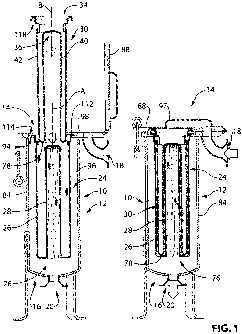
Referring to figure 1, there is provided a filter assembly for filtering
flowable media, shown at 10. The
IFM-FSF-PCT 15
CA 02717696 2010-09-03
WO 2009/109040 PCT/CA2009/000258
filter assembly 10 has a housing 12 with a first open end 14, a first closed
end 16, an inlet 18, and an outlet
20. Other configurations of housings may be used as desired. The filter
assembly 10 has a filter support 24
with a first permeable support portion 26 and a second permeable support
portion 28 nested within the first
permeable support portion 26. The filter support 24 is seated within the
housing 12 between the inlet 18
and the outlet 20 and further includes a filter element 30 that has a second
open end 34 and a second closed
end 36. The filter element 30 is reversed upon itself and positioned between
the first and second permeable
support portions 26 and 28 to form concentrically disposed inner and outer
filtering surfaces 40 and 42.
As shown in figure 3, the second permeable support portion 28 has a surface
area which is substantially
equal to a surface area of the first permeable support portion 26. The second
permeable support portion 28
has a regular undulating periphery 44 in cross section to form a plurality of
lobes 48. Alternatively, the
periphery may also be an irregular undulating periphery. In this case, the
presence of the lobes 48 on the
second permeable support portion 28 has the effect of providing a corrugated
support surface 50. This may
be achieved by the second permeable support portion 28 being corrugated in
cross section therefore
providing an increase surface area (as compared with an equivalent surface
area had the second permeable
support portion not been corrugated in this manner). As shown in figure 2,
other shapes and/or
configurations may be used to similarly increase the surface area of the
second permeable support portion
28, for example star, crescent or cruciform shapes. Also, as illustrated in
figure 2, the inner permeable
support portion may be configured from a single structure or from a plurality
of structures or layers.
Further, as shown in figure 2, the second permeable support portion may be
seen to have a footprint
bounded by a theoretical circle 54 of a predetermined circumference. In this
case, the second permeable
support portion 28 has a plurality of regular formations that provides an
increased circumference of the
second permeable support 28 beyond that of the circumference of the
theoretical circle 54, so that the
circumference of the second permeable support portion 28 is substantially
equal to the circumference of the
first permeable support portion 26. In this case (referring to figure 2) the
term circumference is intended to
mean the length of a trace starting at A and ending at B along the laterally
outward surface of the second
support portion 28 and from C to D along the laterally inward surface of the
first support portion 26.
IFM-FSF-PCT 16
CA 02717696 2010-09-03
WO 2009/109040 PCT/CA2009/000258
As can be seen in figure 4, the first permeable support portion 24 is
cylindrical and has a first inner surface
60 with a first circumference 62 which is configured to be approximately equal
to but not substantially
exceeding a circumference 64 of the filter element. The lobes 48 on the second
permeable support portion
28 provide a plurality of regular elongate projections distributed laterally
therealong to provide a second
circumference 66 that in one example is at most equal to the circumference 64
of the filter element 30. As
can be seen in figure 4, the filter element 30 has a first cylindrical portion
70 to engage the first permeable
support portion 26 and a second cylindrical portion 72 to engage the second
support portion 28. In one
example, the first and second support portions 26 and 28 are arranged to
receive and support the first and
second cylindrical portions 70 and 72, so that the filter material itself has
minimal, if any, folds, where the
filter material is lying on other filter material. Rather, in one example,
substantially all of the filter material
that is neighbouring the first and second support portions is contacting the
first and second support portions
directly. The first and second filtering surfaces are thus arranged to receive
the first and second cylindrical
portions in a substantially continuous basis along their respective
peripheries and lengths with no
substantially excess material of the filter element 30. Thus, in use, local
regions of the filter element in this
example and under typical operating conditions, including for example flow,
pressure and the like will
assume the shape of the local support provided by the corresponding support
portion. In other words, the
second cylindrical portion 72 will assume a pleated configuration
corresponding with the configuration of
the lobes of the inner surface portion while the first cylindrical portion and
the bridging portion will assume
the configuration of the corresponding outer surface, and intermediate
portions, as well as the cap portion.
The first and second permeable support portion 26 and 28 may be perforated,
woven, molded, punched, or
stretched. In this example, as shown in figure 3 the first and second
permeable support portions 26 and 28
are perforated. This perforation may be provided by stamping, metal expanding
step, wire forming or
plastic molding steps. In another example, one or the other of the first
permeable support portion and
second support portion 26 and 28 is perforated.
In some applications, it may be beneficial to provide one or more fixed or
removable bracing portions for
bracing the first support portion, the second support portion, and/or the
intermediate portion against
IFM-FSF-PCT 17
CA 02717696 2010-09-03
WO 2009/109040 PCT/CA2009/000258
operating pressures within the housing. In one example, this may be provided
by one or more fixed or
removable bracing portions as illustrated in figures 4 and 10 at 74. In one
specific example, it may be
useful to provide three or four rings welded at intervals of six inches or so,
for an assembly using the
housing part no FSTBI 121F26150 commercially available from INDUSTRIAL FILTER
MANUFACTURING LIMITED. If desired other bracing structures may be included on,
above or below
the intermediate portion, as well as the first support portion.
As shown in figure 3, the filter support 24 has an intermediate region 76 and
the first permeable support
portion 26 is affixed to the second permeable support portion 28 at the
intermediate region 76. In this
example, the first and second permeable support portions 26 and 28 are welded
together but may be
integrally formed with the intermediate region 76, as desired. Further, the
intermediate region may be
provided in other forms to provide an interconnection between the first and
second permeable support
portions. For instance, the intermediate region 76 may be v-shaped or u-shaped
in cross section and may be
of relatively small in lateral dimension depending on the desired spacing
between the first and second
permeable support portions. It may also be, in some applications, beneficial
to provide additional bracing
on the intermediate region 76, between the inner and outer support portions.
In some cases it may be
intersecting rod or rods connecting the bottom of the outer support portion to
the inner support portion.
As can be seen in figure 1, the second permeable support portion has an open
end through the intermediate
region to reduce flow restriction, though there may be cases in which a closed
end is arranged for other
reasons, such as for additional structural reinforcement. For example, in
figure 7, the second permeable
support portion is shown with a closed or permeable end wall through the
intermediate region. Further, it
can be seen in figure 1 that the filter element includes a bridging portion 78
between the first and second
cylindrical portions, so that, under predefined operating pressures, the
bridging portion 78 is directly
supported by the intermediate portion 76. In another example, the second
permeable support portion 28 is
removably mounted within the first permeable support portion 26 as illustrated
in figure 7. This allows an
existing first support portion 26 to be retrofitted with a second permeable
support portion 28.
IFM-FSF-PCT 18
CA 02717696 2010-09-03
WO 2009/109040 PCT/CA2009/000258
As seen in figure 4, the filter element 30 is cylindrical in shape between the
second open end 34 and the
second closed end 36. The filter element 30 can be considered collapsible or
deformable and has
substantially constant lateral dimensions between the second open 34 end and
the second closed end 36. In
this example, the filter element is made of a single blank 80 of material
formed by welding or other
methods, but also may be seamless. Other configurations and assembly of such
material or materials may
be used as desired, such as those configured from multiple blanks of varying
materials and including
materials with the ability to expand and/or from a stored, packaged or other
pre-operative configuration.
This may provide the benefit of utilizing a filter element whose circumference
is less than the first and
second support portions in some cases.
As shown in figure 1, the housing 10 includes an elongate body portion 84 with
a cover portion 88 to close
the open end 14. The outlet 20 in this example is associated with the closed
end 16 and the inlet 18 is
associated with the cover portion 88. Another example of the housing is shown
in figure 9, which includes
a plurality of filter elements as shown at 92.
In the example of figure 1, the second support portion 28 has a vertical
height equal to or less than that of
the first support portion 26. Other configurations may be used, for example
the second support portion 28
may be higher than that of the first support portion 26, provided there is
sufficient room in the housing 10
to accommodate the second support portion projecting above the first support
portion. In some filter
assemblies, such as that shown in figure 9, the cover portion 88 is convex and
there may be room to have a
second support portion with a height exceeding that of the first support
portion. In some cases, the second
support portion may have a circumference that exceeds that of the first
support portion while not
substantially exceeding the circumference of the second cylindrical portion of
the filter element, though this
may require some residual folding of the first cylindrical portion of the
filter element or expanding the
circumference of the first support portion.
Now referring to figure 1, a fluid boundary member 94 is located within the
housing 12 and is oriented to
define a pair of fluid regions 96, 97 therein. The filter support 24 is seated
at the fluid boundary member
IFM-FSF-PCT 19
CA 02717696 2010-09-03
WO 2009/109040 PCT/CA2009/000258
94.
Referring to figure 9, the fluid boundary member is also shown at 94 and
includes a plate portion 98 with a
first peripheral region 100, and a passage 102 formed therein and arranged
adjacent the first peripheral
region 100. The passage 102 is bordered by a corresponding second peripheral
region 104 and the filter
support 24 extends through a corresponding passage 106 and engages the fluid
boundary member 94 at the
second peripheral region 104.
Now referring to the figures 1, 3 and 4, the filter support 24, in this case,
is provided as a removable basket
110, with a lip 112 to seat on the fluid boundary member 94. The fluid
boundary member 94, in this case,
includes a recess 114 to receive the lip 112 as shown in figure 1.
As shown in figure 1, the filter housing 12 has an elongate first central axis
A and the first and second
permeable support portions are concentrically aligned with a second central
axis B. The second central axis
B, in this case, substantially aligned with the first central axis A. The
second permeable support portion
has plurality of corrugations, each corrugation forming one of the lobes with
a third axis C. Each third axis
C, in this case, is substantially aligned with the second central axis B.
Now referring to figure 1, the filter element 30 has a sealing member 118 that
mates with the fluid
boundary member 94. In another example, the filter element's sealing member
118 may mate with the
fluid boundary member 94 and/or the lip 112 of the filter support 24 as shown
in figure 5. In yet another
example, the filter element's sealing member 118 may mate with the fluid
boundary member 94, the lip 112
of the filter support 24 and the cover portion 88. The filter element 30 may
have one or more raised, flush,
movable and/or integral handles 120 to assist in removal of the filter element
30.
As shown in figures 3 and 5, the first permeable support portion 26 has a
third open end 124 and a seating
portion 126 adjacent the third open end 124 to sealingly engage the second
open end of the filter element.
The first permeable support portion 26 has a distal end region 128 located
adjacent the intermediate region
IFM-FSF-PCT 20
CA 02717696 2010-09-03
WO 2009/109040 PCT/CA2009/000258
76. The second permeable support portion 28 has a third closed end 130 and the
filter element 30 is
dimensioned so that the second closed end 36 of the filter element is
positioned adjacent the third closed
end 130.
In this example shown in figure 6, the filter support 24 includes an annular
bridging portion 132 joining the
first and second permeable support portions 26 and 28 at the intermediate
region 76. The second permeable
support portion 28 includes an end wall portion 134 at the third closed end
130. One or both of the annular
bridging portion 132 and the end wall 134 are permeable.
As shown in figure 3 a cap portion 136 is removably positioned or fixed at the
third end 130, which in this
case may be open or closed. In this example the cap portion 136 is permeable,
by way of passages formed
through a molded element. However, the cap portion may be made permeable with
other materials or
methods such as by, perforating, weaving, punching or stretching. However, in
other cases, the cap portion
may be utilized without being permeable. The cap portion 136 further comprises
a plurality of ridges 138
extending radially outwardly from a central region thereof, each to align with
a corresponding formation in
the second permeable support portion 28.
As shown in figure 8, in another example, the filter assembly has a peripheral
filter ring 142 to engage the
filter support 24, the filter support includes a first interruptive formation
144 to be positioned adjacent the
filter ring 142. The filter ring 142 includes a second formation 146 to be
positioned adjacent and/or engage
the first formation 144 in a complementary fashion, the first and second
formations 144 and 146 being
arranged to engage when the filter ring 142 and filter support 24 are in an
operative fluid sealing orientation
to form an effective fluid seal therebetween.
The first and/or second formations 144 and 146 are arranged so that the
presence of one without the other
in an operative sealing orientation between the filter and filter support
operationally inhibits (or results in a
lack of), the effective seal and allows fluid to be passed without being
filtered.
IFM-FSF-PCT 21
CA 02717696 2010-09-03
WO 2009/109040 PCT/CA2009/000258
As shown in figure 10 there is a kit 150 for use with a liquid filtration
assembly such as that shown in
figure 1 that may include at least one retainer basket 152 and at least one
cap portion 136, for each of the
retainer baskets. The retainer basket 152 has a first permeable support
portion 26 and a second permeable
support portion 28 mounted within the first permeable support portion 26. The
cap portion 136 may be
removably positioned or fixed at the third end 130 of the second permeable
support portion 28. The filter
basket 152 is operable to be seated within a liquid filtration vessel. A
plurality of filter elements 30 are also
provided for use in the permeable retainer basket 152. A set of instructions
for the use of the kit are also
provided at 166.
As shown in figure 11 there is a second kit 156 for retrofitting a permeable
retainer basket, such as that
shown at 158 in figure 7 for use in a liquid filtration assembly. The kit
comprises an inner permeable
support portion 160 that is removably positionable in the permeable retainer
basket. At least one cap
portion 136 is removably positioned or fixed at the third end of the inner
permeable support portion 160. A
plurality of filter elements 30 are also provided for use in the permeable
retainer basket following
installation of the inner permeable support portion. There may require one or
more fastener elements 162
or alternate fastening device or method for fastening the inner permeable
support portion 160 to the outer
permeable retainer basket 158. A set of instructions for the use of the kit
are also provided at 166.
Now, with reference to figure 1, the assembly 10 may be used in the following
manner. First, the user
assembles the filtering assembly by ensuring the filter housing is in a non-
pressurized state in accordance
with safe operating procedures. The user then opens the cover portion 88 of
the housing as shown in figure
1. The user identifies the filter support with the first permeable support
portion and a second permeable
support portion mounted within the first permeable support portion. In some
cases it may be desirable to
remove the filter support. The user takes the filter element that has a second
open end and a second closed
end and then reverses it upon itself. In some cases, the filter element may
also be provided in the reversed
position as shown in figure 1. The filter element is then positioned between
the first and second permeable
support portions to form concentrically disposed inner and outer filtering
surfaces. The user may wish to
use a tool to assist the insertion of the filter element and furthermore
enhance the relative association in
IFM-FSF-PCT 22
CA 02717696 2010-09-03
WO 2009/109040 PCT/CA2009/000258
proximity of the element to the support structure, such as the tool
commercially available from
INDUSTRIAL FILTER MANUFACTURING LIMITED under part number FS 1003.
The user then closes the cover portion and secures the cover in accordance
with safe operating procedures
and delivers unfiltered liquid under predefined operating pressure and /or
conditions to the filter assembly
through the inlet in the open end of the housing. As the unfiltered liquid
enters the housing the filter
element is supported continuously by the first permeable support portion, the
second permeable support
portion, the intermediate portion and the cap portion. The pressurized
unfiltered liquid passes through the
filter element leaving particulates on or in the filter element and cleans the
liquid that will exit an outlet in
the closed end of the housing. The filter element continues to be supported
throughout the fluid filtering
process to a determined point of pressure and contamination capacity of the
support structure under
predefined operating conditions.
Thus, it can be said that there is a relationship between the support portion
and the filter element, in
particular between the second support portion and the circumference of the
filter element. If the
circumference of the filter is too small there may be a risk that the second
support portion will not
sufficiently support the filter element and there may be a chance of damage to
the filter element.
Conversely if there is too much material there may be excessive overlapping of
portions of the filter media
leaving material folding over on itself and may result in correspondingly
reduced efficiency.
Liquid or fluid filtration involves the removal of contaminant particles in a
fluid system. The grade of filter
element chosen for a specific application is usually determined by the size of
the particle to be removed.
Contaminant particles are measured using the "micron" unit of measurement.
Particle size retention, dirt
holding capacity, filtration efficiency and differential pressure are aspects
to consider when choosing the
filter medium.
Thus, in some examples, the second support member may provide equivalent
surface area to the first
support portion to support a filter bag of consistent diameter, but with the
second support member being
IFM-FSF-PCT 23
CA 02717696 2010-09-03
WO 2009/109040 PCT/CA2009/000258
located within a relatively smaller operating diameter, as provided by the
lobed, or other undulating wall
configuration. This may allow, in some cases, one or more of the following:
- increased fluid flow rate capacity through the filter bag,
- increased dirt-holding capacity within the filter bag;
- reduced clean differential pressure drop across the filter bag;
- capacity for higher viscosity of fluid processed through the filter bag;
- ability to constrict the filter porosity for greater efficiency or smaller
particulate retention;
- longer service life or reduction in filter bag change out frequency;
- reduced interference with the fluid flow that decreases "down time" and
maintenance attention;
and reduced costs associated with the use of a filter bag system.
In some examples, the filter unit may provide a filter bag which is primarily
a tubular structure of
extended length. The filter bag is made up of a continuous and constant
diameter tube of varying types
of material. The material may be a polypropylene or polyester needled felt
that is thermally bonded.
However, the filter bag may be made from mesh type material, multi-layer or
high efficiency
configurations, or any number of other flexible porous filter materials. The
seams may also be sealed
with stitching or other forms of seam fastening methods. The'bag may be sealed
at one end along the
width of the tube, perpendicular to the long side seam, collapsing the tube
into a flat conclusion. The
opposite end may be fastened to a ring or plastic flange top, causing the top
of the bag to be forced open,
taking the shape of the top retainer. The tube making up the body of the
filter bag may be longer than a
standard filter bag. However, the final manufacturing process used may shorten
the length of the bag
with the reversal of the bottom section. The bag is upturned within itself so
the bottom portion is aligned
with the inside walls of the top portion. There is a seamless fold connecting
the two portions. This
makes a finished bag with similar length and diameter of a conventional filter
bag. The manufacturing
process may then utilize a semi or fully automated process for precise
finished dimensions and an
economical filter element.
IFM-FSF-PCT 24
CA 02717696 2010-09-03
WO 2009/109040 PCT/CA2009/000258
In some examples, the filter unit may include a basket with a top lip of a
dimension and construction that
offers support and sealing for the basket, as it sits adjacent to the inside
of the housing wall on a
protrusion or ridge. Housing construction may determine the placement and
sealing mechanism for this
component. The top ring may also ensure an appropriate seal to the top support
ring or flange fastened to
the filter bag. Thus, the basket may be used to provide a "bypass free seal"
ensuring all the contaminated
fluid is channelled exclusively through the bag. The term "bypass free seal"
is used in this case to mean
that seal will minimize, if not eliminate passage of contaminated or
unfiltered fluid between the support
structure of the housing and the filter element, without being filtered.
In some examples, the outer sleeve portion of the basket may have a diameter
and a length to follow the
restrictions of the housing within which it is seated. This outer support
portion of the basket is generally
circular and evenly cylindrical along its length, though other configurations
may also be utilized in some
cases. The surface of the support basket may be provided with raising or
depressing portions to create
dimples or protrusions in a pattern that augment the available surface area.
The outer sleeve may then be
fastened to the top ring described above at one end, and the outer sleeve is
furthermore fastened to an
inner core by way of a support material at the opposite end to the top lip.
The support media may be
similar material to the outer and inner core. The material of construction
chosen for the basket may be
perforated stainless steel, but may also encompass a range of other materials,
including those which are
supportive and/or manipulated or moulded into a desired shape with a porosity
significant enough for
adequate fluid throughput.
In some examples, the inner core of the filter unit may be seen to expand the
available surface area by
occupying the cavity formed by the outer support basket wall. This void space
provides residence for the
supplemental internal support core. Occupying a portion of this previously
void space displaces a
significant portion of the dirty fluid, enabling the utilization of the
unexploited region. The inner core
may thus include a porous material similar to the outer basket wall and bottom
union segment that has
been shaped to form a lobed, pleated, or corrugated surface. The longitudinal
protrusions may thus
extend along the full or a partial length of the internal core, between the
bottom support to the top dome
IFM-FSF-PCT 25
CA 02717696 2010-09-03
WO 2009/109040 PCT/CA2009/000258
shaped undulating cap. The height of the internal core relates to the height
of the outer support structure
such that the surface area generated by the protrusions on the core support is
at least equal to the surface
area of the outer support sleeve. It may be desirable in'some cases to reduce
the length of, or to shorten,
the internal core to offer less surface area, though this may limit the
effective length of the filter element
that can be supported by the filter unit and thus reduce surface area.
Thus, in some examples, the filter unit may be adjusted to fit previous filter
housings and provide
significantly increased surface area, and in some cases as much as twice the
filter surface area over other
filter units. The maximization of the surface area is due, in one example, to
the undulating surface of the
inner core. In this case, the filter element, when in the form of a bag, may
be inverted within itself is
relatively economic to manufacture and relatively easy to employ. The filter
unit, in an example, may be
manufactured with a minimal number of seams, comparable to standard filter
bags. The seams can, in
some cases, be a possible source of bypass or rupture. A finished profile of
the filter bag, in one
example, has a dual walled construction, with the inner material sitting
against the outer material. This
arrangement, with the inner and outer portions of the filter bag resting
against each other, provides a filter
bag with a slender filter wall. There is a maximized distance between the
inner dimension of the outer
basket support sleeve wall, and the outermost points of the lobes,
protrusions, pleats, or corrugations
extending from the internal core. The arrangement of the inner core and the
outer sleeve may thus allow,
for example, for ample room for the filter bag to be inserted. The arrangement
of the support and
insertion of the filter bag imposes minimal friction and interference. In
addition to the space left for the
insertion of the filter bag, the inner core may be capped with a convex shaped
dome.
In some examples, a dome top may be provided with a rippled surface having of
a series of radiating
undulations corresponding in number and aligning with similar dimension to the
longitudinal protrusions
travelling along the length of the inner core. A resulting wavy surface
provided by these protrusions may
be seen to rise to the top of the dome where the undulations shrink gradually
until they disappear where
they meet at a common rounded point in the centre at the top of the dome. This
shape may, in one
example, be desirable for some applications, since it provides an enhanced
support for the filter bag due
IFM-FSF-PCT 26
CA 02717696 2010-09-03
WO 2009/109040 PCT/CA2009/000258
to the dome shape and wrinkled surface. The cap may also be porous, allowing
for an additional
filtration opportunity. Also, the undulating dome top may allow for an obtuse,
smooth interface between
the sides of the inner core and the upper cap, so that the filter bag may
easily slide into the cavity
between the inner core and outer support sleeve. The filter unit may be
introduced into an existing
housing providing as much as a 100 percent increase in the flow rate capacity,
dirt holding capacity and
general filter life, utilizing an element that is economically manufactured
and relatively easily inserted
into the support basket comparable to the effort required to insert a standard
bag.
While the present invention has been described with respect to what is
presently considered to be the
preferred embodiments, it is to be understood that the invention is not
limited to the disclosed
embodiments. To the contrary, the invention is intended to cover various
modifications and equivalent
arrangements included within the spirit and scope of the appended claims. The
scope of the following
claims is to be accorded the broadest interpretation so as to encompass all
such modifications and
equivalent structures and functions.
IFM-FSF-PCT 27