Note : Les descriptions sont présentées dans la langue officielle dans laquelle elles ont été soumises.
CA 02718684 20125
- 1
ENGINE MOUNT OF AIRCRAFT AND AIRCRAFT
BACKGROUND OF THE INVENTION
Field of the Invention
The present invention relates to an engine mount of
an aircraft including a turbofan type engine, and the
aircraft.
Description of the Related Art
A turbofan type engine of an aircraft is mounted to
a wing via a structural member called a pylon strut (see,
for example, FIG. 13.4.3 of "Airframe structural design
second edition" by Micheal C. Y. Niu, Hong Kong Conmilit
Press LTD pp. 482 to 483).
As shown in FIG. 4, a pylon strut 1 is provided at
an undersurface of a wing 2 to extend toward a front in a
flying direction. In an engine 4, a fan section 4a at
the front is mounted to an undersurface of the pylon
strut 1 by a front engine mount 5, and a core section 4b
at the rear is mounted to the undersurface of the pylon
strut 1 by a rear engine mount 6.
Forces in various directions work between a side of
the engine 4 and a side of the pylon strut 1. For
example, by the thrust force of the engine 4, and the
force at the time of reverse thrust, the force in a
longitudinal direction works. Further, at the time of
landing, the force in a vertical direction works. As the
CA 02718684 20125
- 2 -
force in the vertical direction, impacts and the like can
be cited, which occur at the time of, for example, hard
landing (landing accompanied by the impact in the
vertical direction), and at the time of belly landing.
Further, at the time of operation of the engine 4, torque
in the rotating direction by rotation of the fan also
works. Therefore, the front engine mount 5 and the rear
engine mount 6 need to have sufficient strength against
these forces.
In recent years, the engine 4 with a high bypass
ratio has been developed, in which the diameter of the
fan section 4a is large with respect to the diameter of
the core section 4b. In the engine 4 with such a high
bypass ratio, the space between the core section 4b and
the pylon strut 1 is increased in the rear part of the
engine 4. With this, the rear engine mount 6 becomes
large in length (becomes large in height).
However, if the rear engine mount 6 becomes large in
length, the moment of the force which works between the
side of the engine 4 and the side of the pylon strut 1
becomes large. As a result, in order to secure the
strength of the rear engine mount 6, the rear engine
mount 6 has to be made thick or the like, and this leads
to an increase in weight.
Further, the front engine mount 5 and the rear
engine mount 6 are provided in a nacelle 7 which forms
the outer shell of the engine 4. In the nacelle 7,
CA 02718684 2010-10-25
- 3 -
various devices are housed especially above the core
section 4b of the engine 4. If the rear engine mount 6
becomes large in length, the housing space for these
devices becomes small, and there is also room for
improvement from the viewpoint of effective use of the
space.
SUMMARY OF THE INVENTION
The present invention is accomplished in view of
such a technical problem, and has an object to provide an
= engine mount of an aircraft and the aircraft, which can
reduce a size of an engine mount and can effectively use
a space in an engine nacelle even in the engine with a
high bypass ratio.
The present invention with such the object provides
an engine mount of an aircraft for suspending an engine
of the aircraft at a pylon strut fixed to a wing of the
aforesaid aircraft. The engine mount includes a front
engine mount which connects a fan section provided at a
front of the engine to the pylon strut, and a rear engine
mount which connects an engine core section provided at a
rear of the engine and having an outside diameter smaller
than that of the fan section to the pylon strut, wherein
the rear engine mount is configured by connecting an
engine side mount member provided at a side of the engine
core section to a pylon side mount member provided at a
side of the pylon strut.
CA 02718684 20125
- 4 -
Like this, at least the rear engine mount is
configured by the engine side mount member and the pylon
side mount member. Thereby, the engine side mount member
and the pylon side mount member can be made short
respectively as compared with the case of using the rear
engine mount made by integrating the engine side mount
member and the pylon side mount member. Thereby, the
moments of the forces which work respectively on the
engine side mount member and the pylon side mount member
due to relative displacement of the engine and wing can
be made small.
Further, the pylon side mount member can include a
pair of plate-shaped main mount members provided to
sandwich the pylon strut therebetween, and a reinforcing
mount member which is sandwiched between the pair of the
main mount members, and reinforces support strength of
the main mount member in a direction to connect the pair
of main mount members.
Further, a pylon side mount member in which the main
mount member and the reinforcing mount member are
integrated can be used.
A reinforcing rod with one end connected to an upper
end portion of the engine side mount member and the other
end connected to a vicinity of a boundary portion of the
engine core section and the fan section may be further
provided. In this case, the height of the engine side
mount member is suppressed to be low, and therefore, the
CA 02718684 20125
-5--.
reinforcing rod also can be installed to be low. Thereby,
when devices are installed between the engine core
section and the pylon strut, the reinforcing rod hardly
interferes with maintenance of these devices, and
maintainability can be improved.
The present invention also provides an aircraft,
wherein an engine is supported at a wing by the engine
mount as described above.
According to the present invention, at least the
rear engine mount is configured by the engine side mount
member and the pylon side mount member. Thereby, the
engine side mount member and the pylon side mount member
can be made short respectively as compared with the case
of using the rear engine mount made by integrating the
engine side mount member and the pylon side mount member.
Thereby, the moments of the forces which work on the
engine side mount member and the pylon side mount member
due to relative displacement of the engine and the wing
can be made small. Accordingly, in the engine with a
high bypass ratio, the engine mount can be made compact,
and the space in the engine nacelle can be effectively
used.
Further, while the support strength in the
longitudinal direction and the vertical direction of the
aircraft corresponding to the directions along the plate
surface is mainly secured by a pair of plate-shaped main
mount members which are provided to sandwich the pylon
CA 02718684 2013-12-30
- 6 -
strut, support strength of the main mount member in the
direction to connect a pair of main mount members, that is,
the thickness direction of the plate is reinforced by the
reinforcing mount member which is inserted between a pair of
main mount members, whereby, support strength for the engine
to every direction can be secured.
Further, the height of the engine side mount member is
suppressed to be low, and therefore, the reinforcing rod can
be installed to be low. Thereby, when the devices are
installed between the engine core section and the pylon
strut, the reinforcing rod hardly interferes with maintenance
of these devices, and maintainability can be improved.
Accordingly, in one aspect the present invention resides
in an engine mount of an aircraft for suspending an engine of
the aircraft at a pylon strut fixed to a wing of said
aircraft, comprising: a front engine mount which connects a
fan section to said pylon strut, said fan section being
provided at a front of said engine; and a rear engine mount
which connects an engine core section to said pylon strut,
said engine core section being provided at a rear of said
engine and said engine core section having an outside
diameter smaller than that of said fan section, wherein at
least said rear engine mount is configured by connecting an
engine side mount member provided at a side of said engine
core section to a pylon side mount member provided at a side
of said pylon strut, wherein said pylon side mount member has
a block shape, and is fixed to an undersurface of said pylon
CA 02718684 2013-12-30
- 6a -
strut, wherein the engine of the aircraft is a turbofan type
engine.
In another aspect the present invention resides in an
engine mount of an aircraft for suspending an engine of the
aircraft at a pylon strut fixed to a wing of said aircraft,
comprising: a front engine mount which connects a fan section
to said pylon strut, said fan section being provided at a
front of said engine; and a rear engine mount which connects
an engine core section to said pylon strut, said engine core
section being provided at a rear of said engine and said
engine core section having an outside diameter smaller than
that of said fan section, wherein at least said rear engine
mount is configured by connecting an engine side mount member
provided at a side of said engine core section to a pylon
side mount member provided at a side of said pylon strut,
wherein said pylon side mount member comprises: a pair of
plate-shaped main mount members provided to sandwich said
pylon strut therebetween, and a reinforcing mount member
which is sandwiched between said pair of main mount members,
and reinforces support strength of said main mount member in
a direction to connect said pair of main mount members.
An engine mount of an aircraft for suspending an engine
mount of an aircraft for suspending an engine of the aircraft
at a pylon strut fixed to a wing of said aircraft,
comprising: a front engine mount which connects a fan section
to said pylon strut, said fan section being provided at a
front of said engine; and a rear engine mount which connects
CA 02718684 2013-12-30
- 6b -
an engine core section to said pylon strut, said engine core
section being provided at a rear of said engine and said
engine core section having an outside diameter smaller than
that of said fan section, wherein at least said rear engine
mount is configured by connecting an engine side mount member
provided at a side of said engine core section to a pylon
side mount member provided at a side of said pylon strut,
wherein said pylon side mount member comprises: a pair of
plate-shaped main mount members provided to sandwich said
pylon strut therebetween, and a reinforcing mount member
which is sandwiched between said pair of main mount members,
and reinforces support strength of said main mount member in
a direction to connect said pair of main mount members; and a
reinforcing rod with one end connected to an upper end
portion of said engine side mount member and the other end
connected to a vicinity of a boundary portion of said engine
core section and said fan section.
In a further aspect the present invention resides in an
engine mount of an aircraft for suspending an engine of the
aircraft at a pylon strut fixed to a wing of said aircraft,
comprising: a front engine mount which connects a fan section
to said pylon strut, said fan section being provided at a
front of said engine; a rear engine mount which connects an
engine core section to said pylon strut, said engine core
section being provided at a rear of said engine and said
engine core section having an outside diameter smaller than
that of said fan section, wherein at least said rear engine
CA 02718684 2013-12-30
- 6c -
mount is configured by connecting an engine side mount member
provided at a side of said engine core section to a pylon
side mount member provided at a side of said pylon strut,
wherein said pylon side mount member has a block shape, and
is fixed to an undersurface of said pylon strut; and a
reinforcing rod with one end connected to an upper end
portion of said engine side mount member and the other end
connected to a vicinity of a boundary portion of said engine
core section and said fan section.
BRIEF DESCRIPTION OF THE DRAWINGS
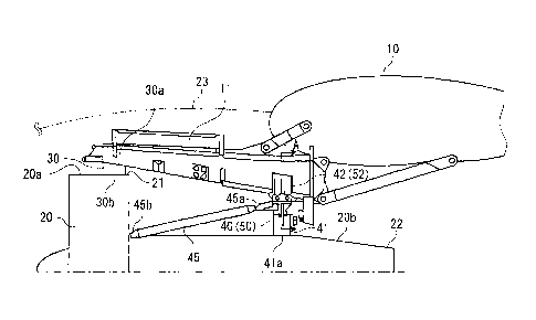
FIG. 1 is a view for showing an engine mounting
structure to a wing to which an engine mount of an aircraft
in the present embodiment is applied;
FIGS. 2A and 2B are views showing a strut side mount
member in a first embodiment, FIG. 2A is a perspective view
seen from a diagonally lower side, and FIG. 2B is a sectional
view in a surface orthogonal to an axial line of a pylon
strut;
FIGS. 3A and 33 are views showing a strut side mount
member in a second embodiment, FIG. 3A is a perspective view
seen from a diagonally lower side, and FIG. 33 is a
CA 02718684 2010-10-25
- 7 -
sectional view in a surface orthogonal to the axial line
of the pylon strut; and
FIG. 4 is a view for showing an engine mounting
structure to a wing to which a conventional engine mount
of an aircraft is applied.
DETAILED DESCRIPTION OF THE PREFERRED EMBODIMENTS
Hereinafter, the invention will be described in
detail based on embodiments shown in the accompanying
drawings.
FIG. 1 is a view for explaining an engine mounting
structure to a wing to which an engine mount of an
aircraft in the present embodiment is applied.
As shown in FIG. 1, a turbofan type engine 20 is
mounted to a wing 10 of an aircraft via a pylon strut 11.
The pylon strut 11 is provided at an undersurface of
the wing 10 to extend toward a front in a flying
direction. The shape of the pylon strut 11 in a section
orthogonal, for example, to a longitudinal direction is
trapezoidal, for example, and its sectional area
gradually reduces toward the front side from the rear
side.
On the front side in the flying direction, the
turbofan type engine 20 comprises a fan section 20a with
a fan incorporated inside a shroud 21 circular in section.
An engine core section 20b which is housed in a housing
22 in a cylindrical shape with a diameter smaller than
CA 02718684 20125
- 8
that of the fan section 20a is provided at the rear of
the fan section 20a. The engine core section 20b
includes a mechanism for driving the fan.
Such an engine 20 has the fan section 20a mounted to
an undersurface of the pylon strut 11 by a front engine
mount 30, and the engine core section 20b mounted to the
undersurface of the pylon strut 11 by a rear engine mount
40.
The engine 20 and the pylon strut 11 are housed in a
cylindrical engine nacelle 23.
In the front engine mount 30, a top surface 30a is
fixed to the undersurface of the pylon strut 11, and an
undersurface 30b is fixed to the shroud 21 of the fan
section 20a of the engine 20, by connecting means such as
bolts.
The rear engine mount 40 comprises an engine side
mount member 41 fixed to the engine 20 side, and a strut
side mount member 42 fixed to the pylon strut 11 side.
Here, the engine side mount member 41 has an
undersurface 41a fixed to the top surface of the housing
22 of the engine core section 20b of the engine 20 by
connecting means such as bolts.
Further, one end 45a of a reinforcing rod 45 is
connected to an upper portion of the engine side mount
member 41. The reinforcing rod 45 has the other end 45b
connected to the vicinity of a connecting portion of the
engine core section 20b and the fan section 20a of the
CA 02718684 20125
- 9 -
,
engine 20. Thereby, the reinforcing rod 45 reinforces
support for the front side of the engine 20.
Meanwhile, as shown in FIGS. 2A and 2B, the strut
side mount member 42 comprises a pair of main support
members (main mount members) 43 and 43, and backup
support members (reinforcing mount members) 44 and 44.
The opposing main support members 43 and 43 are
provided at both sides of the pylon strut 11 with the
pylon strut 11 therebetween. The main support members 43
and 43 have upper portions 43a and 43a fixed to both side
surfaces ha and ha of the pylon strut 11 by bolts or
the like not illustrated. Lower portions 43b and 43b of
the main support members 43 and 43 are provided to extend
vertically downward from the upper portions 43a and 43a
to project downward from the pylon strut 11.
The main support members 43 and 43 are plate-shaped,
and have predetermined widths larger in the longitudinal
direction than the thicknesses in the lateral direction.
The backup support members 44 and 44 are provided
between the lower portions 43b and 43b of the main
support members 43 and 43 which are projected downward
from the pylon strut 11.
Each of the backup support members 44 is formed into
an H-shape in which flanges 44b and 44c orthogonal to a
web 44a are integrally provided at both ends of the web
44a. The flange 44b is opposed to the lower portion 43b
of the main support member 43, the flange 44c is opposed
CA 02718684 20125
- 10 -
to the flange 44c of the other backup support member 44,
and these are connected with connecting means such as
bolts.
In the strut side mount member 42 as above, the
undersurfaces of the main support members 43 and 43, and
the undersurfaces of the backup support members 44 and 44
are provided to form a mounting surface 42a formed by a
continuing plane. The mounting surface 42a of the strut
side mount member 42 and the engine side mount member 41
are butted to each other, and they are connected to each
other by connecting means such as bolts.
In this case, the strut side mount member 42 and the
engine side mount member 41 are connected to each other
in an intermediate portion of the undersurface of the
pylon strut 11 and the top surface of the engine core
section 20b of the engine 20.
According to the configuration as described above,
the engine core section 20b at the rear of the engine 20
is supported by the rear engine mount 40 which comprises
the engine side mount member 41 fixed to the engine 20
side, and the strut side mount member 42 fixed to the
pylon strut 11 side. In this manner, the rear engine
mount 40 is divided into the engine side mount member 41
and the strut side mount member 42, and thereby, even in
the engine 20 with a high bypass ratio in which the
outside diameter of the fan section 20a and the outside
diameter of the engine core section 20b significantly
CA 02718684 20125
- 11 -
differ, the lengths in the vertical direction of the
engine side mount member 41 and the strut side mount
member 42 can be suppressed, as compared with the case of
supporting the engine with one rear engine mount 6 (see
FIG. 4). Thereby, the moments which work on the engine
side mount member 41 and the strut side mount member 42
at the time of operation of the engine 20, at the time of
flight of the aircraft and the like can be made small.
As a result, the lengths of the engine side mount member
41 and the strut side mount member 42 do not have to be
increased, the space in the engine nacelle 23 can be
effectively used, and reduction in weight and the
resultant reduction in cost can be realized.
Further, the reinforcing rod 45 has one end 45a
connected to the upper portion of the engine side mount
member 41. Since the height of the engine side mount
member 41 can be suppressed as described above, the
reinforcing rod 45 also can be suppressed to be low.
Thereby, maintainability of the devices installed in the
space between the engine core section 20b of the engine
20 and the pylon strut 11 can be improved.
Furthermore, in the rear engine mount 40 of the
present embodiment, while the strut side mount member 42
mainly bears the forces in the longitudinal direction,
the vertical direction and the lateral direction by a
pair of main support members 43 and 43, the support
strength against the force especially in the lateral
CA 02718684 20125
- 12 -
direction can be reinforced by the backup support members
44 and 44 provided between these main support members 43
and 43. Thereby, in the strut side mount member 42, the
support strength to every direction can be enhanced. As
a result, the strut side mount member 42 can be reduced
in size and weight while securing required support
strength which is necessary and sufficient.
[Second Embodiment]
Next, a second embodiment of the engine mount of an
aircraft according to the present invention will be
described. In the engine mount of an aircraft which will
be described as follows, the basic configuration is
similar to that shown in the above-described first
embodiment. Therefore, the difference will be mainly
described in the following, and the components common to
the above described first embodiment will be assigned
with the same reference numerals and characters, and the
description of them will be omitted.
As shown in FIG. 1, the engine 20 has the fan
section 20a mounted to the undersurface of the pylon
strut 11 by the front engine mount 30, and has the engine
core section 20b mounted to the undersurface of the pylon
strut 11 by a rear engine mount 50.
The rear engine mount 50 comprises the engine side
mount member 41 fixed to the engine 20 side, and a strut
side mount member 52 fixed to the pylon strut 11 side.
CA 02718684 20125
- 13 -
As shown in FIGS. 3A and 3B, the strut side mount
member 52 has a block shape such that the main support
members 43 and 43 and the backup support members 44 and
44 in the above described first embodiment are integrated.
The strut side mount member 52 has a predetermined
thickness in the vertical direction, and is fixed to the
undersurface of the pylon strut 11 by connecting means
such as bolts.
Such a strut side mount member 52 is formed to have
a shape, a size and quality that can guarantee sufficient
strength and safety by FEM (Finite Element Method)
analysis and the like.
According to the configuration as described above,
the engine core section 20b at the rear of the engine 20
is supported by the rear engine mount 50 formed by the
engine side mount member 41 fixed to the engine 20 side,
and the strut side mount member 52 fixed to the pylon
strut 11 side. In this manner, the rear engine mount 50
is divided into the engine side mount member 41 and the
strut side mount member 52. Thereby, even in the engine
20 with a high bypass ratio in which the outside diameter
of the fan section 20a and the outside diameter of the
engine core section 20b significantly differ, the lengths
in the vertical direction of the engine side mount member
41 and the strut side mount member 52 can be suppressed
as compared with the case of supporting the engine with
one rear engine mount 6 (see FIG. 4). Thereby, the
CA 02718684 20125
- 14 -
moments which work on the engine side mount member 41 and
the strut side mount member 52 at the time of operation
of the engine 20, at the time of flight of the aircraft
and the like can be made small. As a result, the lengths
of the engine side mount member 41 and the strut side
mount member 52 do not have to be increased, and
reduction in weight and the resultant reduction in cost
can be realized.
Furthermore, in the rear engine mount 50 of the
present embodiment, the strut side mount member 52 has
the configuration such that the main support members 43
and 43 and the backup support members 44 and 44 shown in
the above described first embodiment are integrated.
Thereby, while in the strut side mount member 52, the
support strength to every direction can be enhanced, the
number of components can be reduced, and time and effort
and cost for assembly of the components can be suppressed.
In the above-described embodiments, the connecting
means such as bolts is used for assembly of each of the
members, but a shear pin which bears a shearing force in
the direction orthogonal to the connecting surface and a
bolt which fastens two members are preferably used in
combination. The connecting means other than this may be
used as a matter of course.
Further, the configurations or the like of the
engine 20 and the pylon strut 11 are not limited at all.
CA 02718684 2010-10-25
- 15 -
Other than this, the configurations cited in the
above described embodiments can be selected or omitted,
or can be arbitrarily changed to the other configurations,
without departing from the gist of the present invention.