Sélection de la langue

Search

Sommaire du brevet 2720259 

Énoncé de désistement de responsabilité concernant l'information provenant de tiers

Une partie des informations de ce site Web a été fournie par des sources externes. Le gouvernement du Canada n'assume aucune responsabilité concernant la précision, l'actualité ou la fiabilité des informations fournies par les sources externes. Les utilisateurs qui désirent employer cette information devraient consulter directement la source des informations. Le contenu fourni par les sources externes n'est pas assujetti aux exigences sur les langues officielles, la protection des renseignements personnels et l'accessibilité.

Disponibilité de l'Abrégé et des Revendications

L'apparition de différences dans le texte et l'image des Revendications et de l'Abrégé dépend du moment auquel le document est publié. Les textes des Revendications et de l'Abrégé sont affichés :

  • lorsque la demande peut être examinée par le public;
  • lorsque le brevet est émis (délivrance).
(12) Brevet: (11) CA 2720259
(54) Titre français: MULTIPLES ELECTRODES DE CHARGE
(54) Titre anglais: MULTIPLE CHARGING ELECTRODES
Statut: Périmé et au-delà du délai pour l’annulation
Données bibliographiques
(51) Classification internationale des brevets (CIB):
  • B05B 5/04 (2006.01)
  • B05B 5/10 (2006.01)
(72) Inventeurs :
  • SCHAUPP, JOHN F. (Etats-Unis d'Amérique)
  • SAYLOR, AUSTIN A. (Etats-Unis d'Amérique)
(73) Titulaires :
  • FINISHING BRANDS HOLDINGS INC.
(71) Demandeurs :
  • FINISHING BRANDS HOLDINGS INC. (Etats-Unis d'Amérique)
(74) Agent: FINLAYSON & SINGLEHURST
(74) Co-agent:
(45) Délivré: 2014-05-27
(86) Date de dépôt PCT: 2009-03-24
(87) Mise à la disponibilité du public: 2009-10-15
Requête d'examen: 2010-09-30
Licence disponible: S.O.
Cédé au domaine public: S.O.
(25) Langue des documents déposés: Anglais

Traité de coopération en matière de brevets (PCT): Oui
(86) Numéro de la demande PCT: PCT/US2009/038018
(87) Numéro de publication internationale PCT: WO 2009126428
(85) Entrée nationale: 2010-09-30

(30) Données de priorité de la demande:
Numéro de la demande Pays / territoire Date
12/100,172 (Etats-Unis d'Amérique) 2008-04-09

Abrégés

Abrégé français

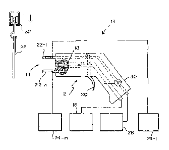
L'invention porte sur un dispositif pour distribuer un matériau de revêtement qui comprend au moins deux électrodes (22) pour un couplage à au moins une alimentation potentielle de grande amplitude (24) de telle sorte que les deux électrodes ou plus (22) sont maintenues sensiblement à deux potentiels de grande amplitude différents, de telle sorte qu'un champ électrique existe entre les deux électrodes ou plus (22). Au moins l'une des deux électrodes ou plus (22) comprend un passage s'étendant à travers elle pour fournir un flux de gaz comprimé à travers cette ou ces électrodes parmi les deux électrodes ou plus (22).


Abrégé anglais


A device for dispensing coating material includes at least two electrodes (22)
for coupling to at least one high-magnitude
potential supply (24) so that the at least two electrodes (22) are maintained
substantially at two different high-magnitude
potentials so that an electric field exists between the at least two
electrodes (22). At least one of the at least two electrodes
(22) includes a passageway extending therethrough to provide a flow of
compressed gas through the at least one of the at least two
electrodes (22).

Revendications

Note : Les revendications sont présentées dans la langue officielle dans laquelle elles ont été soumises.


What is claimed is:
1. A device for dispensing coating material, the device including at least
two electrodes
for coupling to at least one high-magnitude potential supply so that the at
least two
electrodes are maintained substantially at two different high-magnitude
potentials so that an
electric field exists between the at least two electrodes, each of the at
least two electrodes
includes a passageway extending therethrough to provide a flow of compressed
gas through
the at least two electrodes.
2. The apparatus of claim 1 further including a voltage divider coupled to
the at least
one high-magnitude potential supply, the at least two electrodes being coupled
to different
points on the voltage divider to maintain the at least two electrodes at two
different high-
magnitude potentials.
3. The apparatus of claim 1 comprising two high-magnitude potential
supplies having
high-magnitude potential output ports providing said two different high-
magnitude
potentials, each high-magnitude potential output port coupled to a respective
one of the at
least two electrodes.
4. The apparatus of claim 1 wherein the at least two electrodes are coupled
to a
common source of compressed gas.
5. The apparatus of claim 1 wherein the at least two electrodes are coupled
to
respective ones of at least two sources of compressed gas.
6. The device of claim 1 selected from the group consisting of pneumatic
atomizers,
pneumatically-assisted hydraulic atomizers, high-volume, low pressure
pneumatic (HVLP)
atomizers and hydraulic atomizers.
7. Use of the device of claim 1 for dispensing pulverulent coating
material.
6

Description

Note : Les descriptions sont présentées dans la langue officielle dans laquelle elles ont été soumises.


CA 02720259 2012-08-22
Multiple Charging Electrodes
Field of the Invention
This invention relates to electrode configurations and potential supplies
for coating dispensing devices (hereinafter sometimes spray guns or guns).
Background
Various types of manual and automatic spray guns are known. There are,
for example, the automatic and manual spray guns illustrated and described in
the
following listed U.S. patents and published applications: 2006/0081729;
2003/0006322;
U.S. Pat. Nos. 7,296,760; 7,296,759; 7,292,322; 7,247,205; 7,217,442;
7,166,164;
7,143,963; 7,128,277; 6,955,724; 6,951,309; 6,929,698; 6,916,023; 6,877,681;
6,854,672; 6,817,553; 6,796,519; 6,790,285; 6,776,362; 6,758,425; RE38,526;
6,712,292; 6,698,670; 6,679,193; 6,669,112; 6,572,029; 6,460,787; 6,402,058;
U.S. Pat,
No. RE36,378; 6,276,616; 6,189,809; 6,179,223; 5,836,517; 5,829,679;
5,803,313; U.S.
Pat. No. RE35,769; 5,639,027; 5,618,001; 5,582,350; 5,553,788; 5,400,971;
5,395,054;
D349,559; 5,351,887; 5,332,159; 5,332,156; 5,330,108; 5,303,865; 5,299,740;
5,289,974; 5,284,301; 5,284,299; 5,236,129; 5,209,405; 5,209,365; 5,178,330;
=
5,119,992; 5,118,080; 5,180,104; D325,241; 5,090,623; 5,074,466; 5,064,119;
5,054,687; 5,039,019; D318,712; 5,022,590; 4,993,645; 4,934,607; 4,934,603;
4,927,079; 4,921,172; 4,911,367; D305,453; D305,452; D305,057; D303,139;
4,844,342; 4,819,879; 4,770,117; 4,760,962; 4,759,502; 4,747,546; 4,702,420;
4,613,082; 4,606,501; 4,572,438; D287,266; 4,537,357; 4,529,131; 4,513,913;
4,483,483; 4,453,670; 4,437,614; 4,433,812; 4,401,268; 4,361,283; D270,368;
D270,367; D270,180; D270,179; RE30,968; 4,331,298; 4,289,278; 4,285,446;
4,266,721; 4,248,386; 4,214,709; 4,174,071; 4,174,070; 4,171,100; 4,169,545;
4,165,022; D252,097; 4,133,483; 4,116,364; 4,114,564; 4,105,164; 4,081,904;
4,066,041; 4,037,561; 4,030,857; 4,020,393; 4,002,777; 4,001,935; 3,990,609;
3,964,683; 3,940,061; 3,169,883; and, 3,169,882. There are also the
disclosures of WO
2005/014177 and WO 01/85353. There are also the Ransburg model REA 3, REA 4,
REA 70, REA 90, REM and M-90 guns, all available from 1TW Ransburg, 320
Phillips
Avenue, Toledo, Ohio, 43612-1493.
The disclosures of these references may be referred to for details of the
references. The above listing is not intended to be a representation that a
complete search
1

CA 02720259 2013-04-24
-
of all relevant art has been made, or that no more pertinent art than that
listed exists,
or that the listed art is material to patentability. Nor should any such
representation
be inferred.
Disclosure of the Invention
In a broad aspect, the invention pertains to a device for dispensing
coating material. The device includes at least two electrodes for coupling to
at least
one high-magnitude potential supply so that the at least two electrodes are
maintained substantially at two different high-magnitude potentials so that an
electric
field exists between the at least two electrodes. Each of the at least two
electrodes
includes a passageway extending therethrough to provide a flow of compressed
gas
through the at least two electrodes.
Illustratively, a voltage divider is coupled to the at least one high-
magnitude potential supply. The at least two electrodes are coupled to
different
points on the voltage divider to maintain the at least two electrodes at two
different
high-magnitude potentials.
Alternatively illustratively, two high-magnitude potential supplies
having high-magnitude potential output ports provide the two different high-
magnitude potentials. Each high magnitude potential output port is coupled to
a
respective one of the at least two electrodes.
Illustratively, the at least two electrodes are coupled to a common
source of compressed gas.
Alternatively illustratively, the at least two electrodes are coupled to
respective ones of at least two sources of compressed gas.
Illustratively, the device is selected from the group consisting of
pneumatic atomizers, pneumatically-assisted hydraulic atomizers, high-volume,
low
pressure pneumatic (HVLP) atomizers and hydraulic atomizers.
Alternatively illustratively, the device comprises a device for
dispensing pulverulent coating material (hereinafter sometimes coating powder
or
powder).
2

CA 02720259 2010-09-30
WO 2009/126428
PCT/US2009/038018
Brief Description of the Drawings
The invention may best be understood by referring to the following
detailed description and accompanying drawings which illustrate the invention.
In the
drawings:
Fig. 1 illustrates a highly diagrammatic side elevational view of a system
constructed according to the invention;
Fig. 2 highly diagrammatically illustrates an alternative detail to a detail
illustrated in Fig. 1;
Fig. 3 highly diagrammatically illustrates an alternative detail to a detail
illustrated in Fig. 1;
Fig. 4 highly diagrammatically illustrates an alternative detail to a detail
illustrated in Fig. 1; and,
Fig. 5 highly diagrammatically illustrates an alternative detail to a detail
illustrated in Fig. 1.
Detailed Descriptions of Illustrative Embodiments
Fig. 1 illustrates a coating dispensing system 10 including a coating
dispensing device, or gun, 12. Device 12 illustratively is a manual spray gun,
although it
should be understood that the invention is equally applicable to so-called
automatic spray
guns as well. Additionally, while the illustrated gun 12 is a hydraulic gun,
the invention
is equally applicable to pneumatic (hereinafter sometimes air), pneumatically
assisted
hydraulic (hereinafter sometimes AAA), and high-volume, low-pressure pneumatic
(hereinafter sometimes HVLP) guns. Additionally, the invention is equally
applicable to
coating dispensing devices for dispensing coating powders. Gun 12 includes a
nozzle 14
through which coating material from a source 16 is dispensed under the control
of a
valve 18. Source 16 may be a source of liquid coating material or a source of
coating
powder such as, for example, a fluidized bed. The position of valve 18 needle
is, in turn,
controlled by the gun 12 trigger 20 position. On a manual gun, trigger 20
position is
controlled by hand by an operator. On an automatic gun, trigger 20 position is
typically
controlled by a process controller, such as, for example, an Allen-Bradley
controller.
The coating material dispensed through nozzle 14 is charged by two or
more electrodes 22-1,. . . 22-n, only two of which are illustrated in the
drawings.
Electrodes 22-1,. . . 22-n are in the form of hollow needles or small gauge
tubes.
Different high-magnitude (typically negative) electrostatic potentials are
coupled from
3

CA 02720259 2012-08-22
= =
(a) high-magnitude potential source(s) 24-1...24-m, to electrodes 22-1,...22-
n. In this
way, (an) electric field(s) exist(s) not only between each electrode 22-
1,...22-n and
articles 26 (hereinafter sometimes targets) to be coated by the coating
material
dispensed through nozzle 14, but also between the electrodes 22-1...22-n
themselves.
Additionally, compressed gas, illustratively air, is supplied from a source 28
of
compressed gas, illustratively through a valve V controlled via control
connection 30
by the trigger 20 position, to the base of each electrode 22-1,...22-n. Thus,
as
coating material is flowing through nozzle 14, compressed gas is flowing
through
electrodes 22-1,...22-n. This assists in maintaining the electrodes 22-1,...22-
n
relatively free of coating material. This assists in the flow of charge from
electrodes
22-1,...22-n to the coating material as it is being dispensed, which, in turn,
improves
the transfer efficiency of coating material to the articles or targets 26 as
they are
presented in front of gun 12, illustratively on a grounded conveyor 32, for
coating.
The high-magnitude potential source(s) 24-1, . . 24-m need not be
separate power supplies. Instead, they cart be provided by a common supply
feeding a
voltage divider 36 characterized by impedances z1 and z2 which may be provided
within
the body of gun 12, or may be provided within the power supply, or may be a
separate
voltage divider to which the power supply and electrodes 22-1, . . . 22-n are
coupled.
The generalized impedance voltage divider 36 is illustrated in Fig. 2. The
voltage
divider may, for example, take the form of a resistive voltage divider 36'
illustrated in
Fig. 3. It may also take the form of a capacitive voltage divider 36"
illustrated in Fig. 4,
with the constraint that the capacitances must be sufficiently small that the
divider cannot
store so much charge Q = CV as to create hazardous operating conditions in the
coating
environment.
It should also be understood that while the resistors and capacitors of the
various voltage dividers 36, 36', 36" are illustrated as separate components,
one or more
of these may be components, a resistor or capacitor, for example, that are
already
incorporated into the gun 12 for other known purposes, such as, for example,
as part of a
high voltage rectifier and multiplier. Ordinarily, these are Cockcroft-Walton
multipliers,
sometimes referred to as cascades.
Additionally, it should be understood that, while the supplies of
compressed gas to the bases of the electrodes 22-1,. . . 22-n are illustrated
as originating
from a common source 28 of compressed gas, the electrodes 22-1,. . . 22-n may
be
4

CA 02720259 2012-08-22
supplied from two or more sources 28-1...28-p through individually respective
valves
like valve V under the control of trigger 20. This is illustrated in Fig. 5.
Also in
Fig. 5, the tube elecrodes are illustrated as having outer ends beveled at
angles of
about 30 . Ordinarily, the angle of bevel should not be less than about 30 ,
as the
ends of the tubes become "hot spots" for potential electrostatic discharge.
5

Dessin représentatif
Une figure unique qui représente un dessin illustrant l'invention.
États administratifs

2024-08-01 : Dans le cadre de la transition vers les Brevets de nouvelle génération (BNG), la base de données sur les brevets canadiens (BDBC) contient désormais un Historique d'événement plus détaillé, qui reproduit le Journal des événements de notre nouvelle solution interne.

Veuillez noter que les événements débutant par « Inactive : » se réfèrent à des événements qui ne sont plus utilisés dans notre nouvelle solution interne.

Pour une meilleure compréhension de l'état de la demande ou brevet qui figure sur cette page, la rubrique Mise en garde , et les descriptions de Brevet , Historique d'événement , Taxes périodiques et Historique des paiements devraient être consultées.

Historique d'événement

Description Date
Le délai pour l'annulation est expiré 2022-03-01
Lettre envoyée 2021-03-24
Lettre envoyée 2021-03-01
Lettre envoyée 2020-08-31
Inactive : COVID 19 - Délai prolongé 2020-08-19
Inactive : COVID 19 - Délai prolongé 2020-08-06
Inactive : COVID 19 - Délai prolongé 2020-07-16
Inactive : COVID 19 - Délai prolongé 2020-07-02
Inactive : COVID 19 - Délai prolongé 2020-06-10
Inactive : COVID 19 - Délai prolongé 2020-05-28
Inactive : COVID 19 - Délai prolongé 2020-05-14
Inactive : COVID 19 - Délai prolongé 2020-04-28
Inactive : COVID 19 - Délai prolongé 2020-03-29
Représentant commun nommé 2019-10-30
Accordé par délivrance 2014-05-27
Inactive : Page couverture publiée 2014-05-26
Préoctroi 2014-03-06
Inactive : Taxe finale reçue 2014-03-06
Un avis d'acceptation est envoyé 2013-10-04
Lettre envoyée 2013-10-04
Inactive : QS réussi 2013-09-26
Inactive : Approuvée aux fins d'acceptation (AFA) 2013-09-26
Lettre envoyée 2013-08-07
Modification reçue - modification volontaire 2013-04-24
Inactive : Dem. de l'examinateur par.30(2) Règles 2013-01-23
Modification reçue - modification volontaire 2012-08-22
Inactive : Dem. de l'examinateur par.30(2) Règles 2012-03-02
Inactive : CIB attribuée 2012-02-17
Inactive : CIB enlevée 2012-02-17
Inactive : CIB en 1re position 2012-02-17
Inactive : CIB attribuée 2012-02-17
Inactive : Page couverture publiée 2011-01-04
Lettre envoyée 2010-12-01
Inactive : Acc. récept. de l'entrée phase nat. - RE 2010-12-01
Inactive : CIB en 1re position 2010-11-26
Inactive : CIB attribuée 2010-11-26
Demande reçue - PCT 2010-11-26
Toutes les exigences pour l'examen - jugée conforme 2010-09-30
Exigences pour une requête d'examen - jugée conforme 2010-09-30
Exigences pour l'entrée dans la phase nationale - jugée conforme 2010-09-30
Demande publiée (accessible au public) 2009-10-15

Historique d'abandonnement

Il n'y a pas d'historique d'abandonnement

Taxes périodiques

Le dernier paiement a été reçu le 2014-03-05

Avis : Si le paiement en totalité n'a pas été reçu au plus tard à la date indiquée, une taxe supplémentaire peut être imposée, soit une des taxes suivantes :

  • taxe de rétablissement ;
  • taxe pour paiement en souffrance ; ou
  • taxe additionnelle pour le renversement d'une péremption réputée.

Veuillez vous référer à la page web des taxes sur les brevets de l'OPIC pour voir tous les montants actuels des taxes.

Titulaires au dossier

Les titulaires actuels et antérieures au dossier sont affichés en ordre alphabétique.

Titulaires actuels au dossier
FINISHING BRANDS HOLDINGS INC.
Titulaires antérieures au dossier
AUSTIN A. SAYLOR
JOHN F. SCHAUPP
Les propriétaires antérieurs qui ne figurent pas dans la liste des « Propriétaires au dossier » apparaîtront dans d'autres documents au dossier.
Documents

Pour visionner les fichiers sélectionnés, entrer le code reCAPTCHA :


Pour visualiser une image, cliquer sur un lien dans la colonne description du document. Pour télécharger l'image (les images), cliquer l'une ou plusieurs cases à cocher dans la première colonne et ensuite cliquer sur le bouton "Télécharger sélection en format PDF (archive Zip)" ou le bouton "Télécharger sélection (en un fichier PDF fusionné)".

Liste des documents de brevet publiés et non publiés sur la BDBC .

Si vous avez des difficultés à accéder au contenu, veuillez communiquer avec le Centre de services à la clientèle au 1-866-997-1936, ou envoyer un courriel au Centre de service à la clientèle de l'OPIC.


Description du
Document 
Date
(aaaa-mm-jj) 
Nombre de pages   Taille de l'image (Ko) 
Page couverture 2014-05-07 1 38
Description 2010-09-30 5 235
Abrégé 2010-09-30 2 65
Revendications 2010-09-30 1 45
Dessins 2010-09-30 1 18
Dessin représentatif 2011-01-04 1 9
Page couverture 2011-01-04 2 41
Description 2012-08-22 5 214
Revendications 2012-08-22 1 38
Dessins 2012-08-22 1 19
Revendications 2013-04-24 1 37
Description 2013-04-24 5 213
Dessin représentatif 2014-05-07 1 7
Accusé de réception de la requête d'examen 2010-12-01 1 176
Rappel de taxe de maintien due 2010-12-01 1 111
Avis d'entree dans la phase nationale 2010-12-01 1 202
Courtoisie - Certificat d'enregistrement (document(s) connexe(s)) 2010-12-01 1 103
Avis du commissaire - Demande jugée acceptable 2013-10-04 1 163
Avis du commissaire - Non-paiement de la taxe pour le maintien en état des droits conférés par un brevet 2020-10-19 1 544
Courtoisie - Brevet réputé périmé 2021-03-29 1 540
Avis du commissaire - Non-paiement de la taxe pour le maintien en état des droits conférés par un brevet 2021-05-05 1 535
PCT 2010-09-30 8 274
Correspondance 2014-03-06 1 26